2018 MITSUBISHI OUTLANDER PHEV Press and hold
[x] Cancel search: Press and holdPage 273 of 538

NOTE•When the select position is in the “P”
(PARK), the “R” (REVERSE) or the “N”
(NEUTRAL) position.
• While the brake pedal is being depressed.
• When the parking brake is applied.
• When the system determines that its per-
formance has been degraded due to con-
taminants adhered to the sensor.
• When there is any abnormality in the sys-
tem.
To increase the set speed
There are two ways to increase the set speed.
By using the “RES +” switch:
The set speed increases by 1 km/h (1 mph) every time you push up the “RES +” switch
while the ACC control is working. If you hold the switch pushed up, the set speed in-creases in 5 km/h (3 mph) increments.
CAUTIONl The setting speed should be set up the suita-
ble speed according to a situation.NOTEl There is some time lag between the setting
to a new speed and actually accelerating tothat speed.
l Speed setting operation is possible even in
presence of a vehicle in front. In this case, however, the set speed alone increases with-
out actual acceleration taking place.
l When the switch is held pushed, a buzzer
sounds every time the set speed changes.
By using the accelerator pedal:
When the accelerator pedal is depressed
while driving with the ACC control working,you can accelerate the vehicle temporarily
beyond the presently set speed.
At the point where the vehicle speed is raised
to your desired speed, push down and release
the “SET -” switch; the new speed is then set in the system.CAUTIONl The ACC braking control and proximity
alarm functions will not work while the ac- celerator pedal is depressed.NOTEl The set speed indication on the display turns
to “---” when the accelerator pedal is de- pressed. This indication remains as long as
the pedal is in a depressed position.
l The ACC control at the original set speed re-
sumes as soon as you release the accelerator
pedal. Under certain conditions, however,
the braking control and alarming functions of ACC may not work for a short while afterreleasing the accelerator pedal.
Adaptive Cruise Control System (ACC)*
7-59OGGE18E1Starting and driving7
Page 274 of 538
NOTElSet speed adjustment is impossible while the
accelerator pedal is in a depressed position.
To decrease the set speed
There are two ways to decrease the set speed.
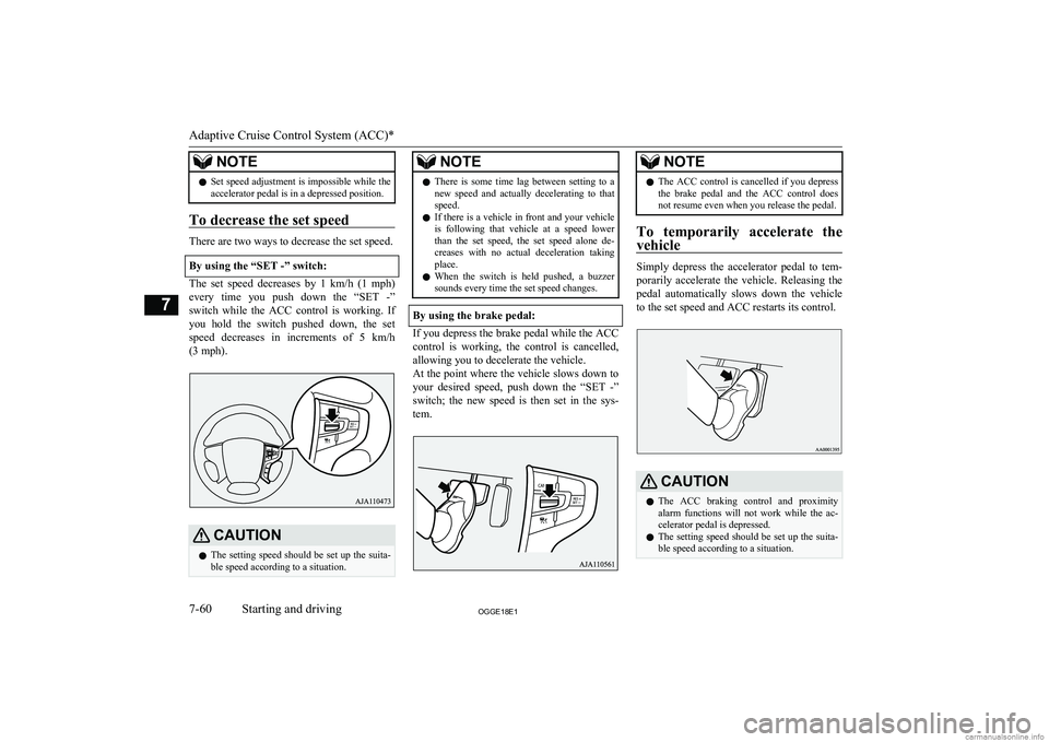
By using the “SET -” switch:
The set speed decreases by 1 km/h (1 mph) every time you push down the “SET -”switch while the ACC control is working. If
you hold the switch pushed down, the set
speed decreases in increments of 5 km/h (3 mph).
CAUTIONl The setting speed should be set up the suita-
ble speed according to a situation.NOTEl There is some time lag between setting to a
new speed and actually decelerating to that
speed.
l If there is a vehicle in front and your vehicle
is following that vehicle at a speed lower
than the set speed, the set speed alone de- creases with no actual deceleration taking
place.
l When the switch is held pushed, a buzzer
sounds every time the set speed changes.
By using the brake pedal:
If you depress the brake pedal while the ACC
control is working, the control is cancelled,allowing you to decelerate the vehicle.
At the point where the vehicle slows down to
your desired speed, push down the “SET -” switch; the new speed is then set in the sys-tem.
NOTEl The ACC control is cancelled if you depress
the brake pedal and the ACC control does
not resume even when you release the pedal.
To temporarily accelerate the
vehicle
Simply depress the accelerator pedal to tem- porarily accelerate the vehicle. Releasing the
pedal automatically slows down the vehicle to the set speed and ACC restarts its control.
CAUTIONl The ACC braking control and proximity
alarm functions will not work while the ac- celerator pedal is depressed.
l The setting speed should be set up the suita-
ble speed according to a situation.
Adaptive Cruise Control System (ACC)*
7-60OGGE18E1Starting and driving7
Page 277 of 538
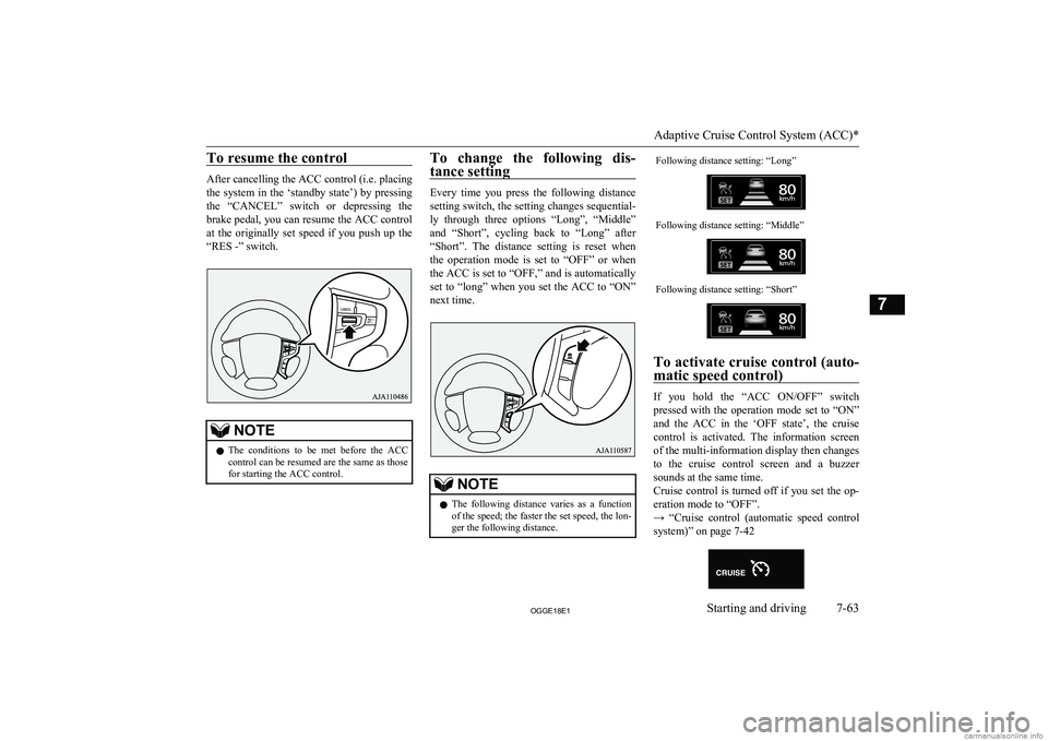
To resume the control
After cancelling the ACC control (i.e. placing
the system in the ‘standby state’) by pressing the “CANCEL” switch or depressing the
brake pedal, you can resume the ACC control
at the originally set speed if you push up the
“RES -” switch.
NOTEl The conditions to be met before the ACC
control can be resumed are the same as those for starting the ACC control.To change the following dis-
tance setting
Every time you press the following distance
setting switch, the setting changes sequential- ly through three options “Long”, “Middle”
and “Short”, cycling back to “Long” after “Short”. The distance setting is reset when
the operation mode is set to “OFF” or when the ACC is set to “OFF,” and is automatically
set to “long” when you set the ACC to “ON”
next time.
NOTEl The following distance varies as a function
of the speed; the faster the set speed, the lon- ger the following distance.Following distance setting: “Long”Following distance setting: “Middle”Following distance setting: “Short”
To activate cruise control (auto-
matic speed control)
If you hold the “ACC ON/OFF” switch
pressed with the operation mode set to “ON” and the ACC in the ‘OFF state’, the cruisecontrol is activated. The information screen
of the multi-information display then changes to the cruise control screen and a buzzer
sounds at the same time.
Cruise control is turned off if you set the op-
eration mode to “OFF”.
→ “Cruise control (automatic speed control system)” on page 7-42
Adaptive Cruise Control System (ACC)*
7-63OGGE18E1Starting and driving7
Page 280 of 538

Once the emergency braking has worked, you
are alerted to this by a message on the infor- mation screen of the multi-information dis- play.
The FCM braking function operates at the
following vehicle speed:
l Against a vehicle: Approximately
5 km/h (3 mph) to 80 km/h (50 mph).
l Against a pedestrian: Approximately
5 km/h (3 mph) to 65 km/h (40 mph).
CAUTIONl Do not use the FCM as a normal braking.
l After your vehicle has stopped following the
activation of the FCM, automatic braking is released. As the vehicle will then start creep-
ing, be sure to depress the brake pedal to
hold the vehicle stationary.CAUTIONl When applying the brake during the auto-
matic braking condition the pedal will feel firm.
This is not abnormal.
You can apply more pressure to the pedal to
assist in braking.
l In the following situations, the system pro-
vides neither control nor alarming.
• When a vehicle or a pedestrian suddenly
cuts in front of your vehicle.
• When the distance from a vehicle or a pe-
destrian in front is extremely short.
• To an oncoming vehicle.
• When the select position is in the “P”
(PARK) or the “R” (REVERSE) position.
• When the FCM has detected a problem in
the system.
l If the ASC is deactivated, the FCM braking
function will not operate. Refer to “Active
Stability Control (ASC)” on page 7-40.
l The FCM may or may not detect a motorcy-
cle, bicycle or wall depending on the situa-
tion. The FCM is not designed to detect these objects.
l The forward collision warning function
and/or the FCM braking function may not
activate in the following situations.
• When a vehicle suddenly appear just in
front of your vehicle.
• When a vehicle cuts in front of your vehi-
cle very closely.
• When the vehicle in front is offset to the
left or right.CAUTION• When the vehicle in front is towing a
trailer.
• A freight trailer that is not carrying a con-
tainer.
• The vehicle has a protruding load from
the carrier.
• The vehicle has a low vehicle height.
• The vehicle has an extremely high ground
clearance.
• When a vehicle in front is extremely dirty.
• When a vehicle in front is covered with
snow.
• When a vehicle in front has a large glass
surface.
• When a vehicle in front does not have re-
flectors (lamp reflector) or the position of the reflector is low.
• When a vehicle in front is a car carrier or
a similar shaped vehicle.
• When there is a different object near the
vehicle.
• When driving on a road with many and
successive curves, including when pass-
ing their entrances and outlets.
• When accelerating and decelerating
quickly.
• When the system recognizes driver’s
steering, accelerating, braking or gear
shifting actions as evasive actions to
avoid collision.
• When you are driving on a road with
steep and alternating up and down slopes.
• When driving on a slippery road covered
by rain water, snow, ice etc.
Forward Collision Mitigation System (FCM)*
7-66OGGE18E1Starting and driving7
Page 283 of 538

NOTElWhen the FCM and UMS ON/OFF switch is
held pressed to change the ON/OFF state ofthe FCM, the ON/OFF state of the UMS is
also changed at the same time.
To turn on/off the system
You can switch the system from OFF to ON
or ON to OFF if you hold the FCM and UMS ON/OFF switch pressed when the operation mode is set to “ON”.
Once the system is turned on, the information
screen of the multi-information display shows the collision alarm timing currently se- lected, and the
indicator on the screen
goes out.
When you turn off the system, the following message appears on the screen and the
in-
dicator comes on.
Cycling the operation mode to ON will set
the FCM back ON.
NOTEl The indicator is combined with the
“UMS OFF” indicator.
To change alarm timing
Give a short press to the FCM and UMS
ON/OFF switch to change the timing at which the frontal collision alarm is triggered. Every time you press the switch, the alarm
timing changes between three levels: “FAR”
(earlier alarming), “MIDDLE” (normally alarming) or “NEAR” (later alarming).
As you make selection, the selected alarm timing is displayed on the information screenof the multi-information display. Even after
turning off the FCM or setting the operation mode to “OFF”, the system retains your last
selected alarm timing in memory.
When “FAR” is selected
When “MIDDLE” is selected
When “NEAR” is selected
CAUTIONl For the FCM brake prefill, the FCM brake
assist and the FCM braking functions, the function triggering timing cannot be changed.When a problem is detected
E00652100023
When the FCM system determines that its
performance has been degraded, the FCM
will become inoperative.
Forward Collision Mitigation System (FCM)*
7-69OGGE18E1Starting and driving7
Page 300 of 538

How to operate LDW
E00635801165
The indication on the information screen ofthe multi-information display changes as fol-
lows depending on the state of the system.
Turning on the system
When you set the operation mode to “ON”, the “LDW” indicator appears on the informa-tion screen of the multi-information display,
showing that the system is placed in the ‘ON state’.
Turning off the system
When you press the LDW switch, the
“LDW” indicator on the information screen of the multi-information display goes out,
showing that the system is placed in the ‘OFF state’. Press the switch again, the system re-
turns to “ON”.
Setting of the LDW starting state
You can make the setting of the LDW
ON/OFF state when the operation mode is put in ON as follows:
l LDW 1 (Factory setting):
Every time the LDW will automatically be turned on.
l LDW 2: The LDW ON/OFF state just
before putting the operation mode in OFF is stored.
Setting the LDW mode
1. Press the LDW switch to turn off the
LDW.
2. Press again and hold the LDW switch
for more than 10 seconds.
3. When you release the LDW switch, the
LDW mode is changed and it appears on the multi information display.
or
Standby state
In the standby mode, the system is capable of
recognizing the lane in which your vehicle is positioned and issuing audible warning whenyour vehicle goes out of the lane.
The system automatically shifts from the
‘ON state’ to the ‘standby state’ if all of the following conditions are simultaneously met.
The “LDW” indicator in the information dis- play changes to
indicator (green).
Lane Departure Warning (LDW)*
7-86OGGE18E1Starting and driving7
Page 303 of 538

CAUTION•When driving on a slippery road covered
by rain water, snow, ice, etc.
• When passing through a place where the
brightness suddenly changes, like the inlet or outlet of a tunnel.
• When turning steep curves.
• When the road surface is reflecting the
light shining from the direction opposite
to the running direction.
• Vehicle largely lurches when it is running
over steps or other irregularities of the
road surface.
• When the headlamp illumination is inade-
quate because of contaminated or deterio-
rated lenses or improperly aimed head- lamps.
• When the vehicle is leaning much to one
side due to heavy luggage on it or improp-
erly adjusted tyre pressures.
• When oncoming vehicles’ headlamps
shine the sensor.
• When the vehicle is equipped with non-
standard tyres (including excessively worn tyres), is using a snow traction de-
vice (tyre chains), or has non-specified
components such as a modified suspen- sion.
• When the windscreen is covered with wa-
ter droplets, snow, dust, etc.
l Follow the instructions given below to keep
your LDW in good operating conditions.
• Always keep the windscreen clean.CAUTION•Avoid applying a strong shock or pressure
to the sensor. Do not attempt to detach or disassemble it.
• Do not put anything like a sticker on the
area in front of the sensor lens of the windscreen.
• Use only
MITSUBISHI MOTORS GEN-
UINE Parts when replacing the wind-
screen wipers.Tyre pressure monitoring
system (TPMS) E00637100282
The tyre pressure monitoring system (TPMS)
uses tyre inflation pressure sensors (A) on the wheels to monitor the tyre inflation pressures.
The system only indicates when a tyre is sig-
nificantly under-inflated.
The base tyre pressure can be set at desired value by the driver with the reset function ex-
ecution. (The low pressure warning threshold is set based on the reset.)
The tyre inflation pressure sensor IDs for two
sets of tyres can be registered by aMITSUBISHI MOTORS Authorized Service
Point, and the valid ID set can be switched by the Multi-information display switch (It’s
beneficial in case of seasonal tyre change be-
tween summer tyre and winter tyre.)NOTEl The tyre pressure monitoring system
(TPMS) is not a substitute for regularlychecking tyre inflation pressures.
Be sure to check the tyre inflation pressures as described in “Tyres” on page 11-10.
l The tyre inflation pressure sensor (B) is in-
stalled in the illustrated location.
• On vehicles with the type 1 sensor which
has the metallic air valve (C), replace
grommet and washer (D) with the new ones when the tyre is replaced.
Tyre pressure monitoring system (TPMS)
7-89OGGE18E1Starting and driving7
Page 307 of 538

NOTElTyre inflation pressures vary with the ambi-
ent temperature. If the vehicle is subjected to large variations in ambient temperature, the tyre inflation pressures may be underinflated
(causing the warning lamp/display come on) when the ambient temperature is relatively low. If the warning lamp/display comes on,
adjust the tyre inflation pressure.Whenever the tyres and wheels
are replaced with new ones
E00637400025
If new wheels with new tyre inflation pres- sure sensors are installed, their ID codes must be programmed into the tyre pressure moni- toring system. Have tyre and wheel replace-
ment performed by a MITSUBISHI
MOTORS Authorized Service Point to avoid
the risk of damaging the tyre inflation pres- sure sensors. If the wheel replacement is not
done by a MITSUBISHI MOTORS Author-
ized Service Point, it is not covered by your warranty.
CAUTIONl The use of non-genuine wheels will prevent
the proper fit of the tyre inflation pressure sensors, resulting air leakage or damage of
the sensors.Reset of low tyre pressure
warning threshold
E00637500071
The threshold is set based on the tyre pres-
sure which the reset function is executed by
following procedure. 1. Operate the multi-information display
switch to switch the information screen
to the menu screen.
Refer to “Multi information display switch” on page 6-04.
Refer to “Changing the function set-
tings” on page 6-15.
2. Lightly press the multi-information dis-
play switch to select “
” (reset
of low tyre pressure warning threshold).
3. Hold down the multi-information dis-
play switch for about 3 seconds or more, the buzzer sounds.
4. The warning lamp start flashing slowly.
5. Drive for a while. The reset is completed
if the warning lamp goes out.NOTEl The reset function should be executed every
time when the tyre pressure or tyre rotationis adjusted.
l The reset function should be executed when
the tyre is cold. If it is executed when the
tyre is warm (e.g. after driving), there may be a low tyre pressure warning earlier than
usual.Tyre ID set change
E00637600072
In case that 2 sets of tyre inflation pressure
sensor ID are registered in the receiver, the
valid tyre ID set can be changed by following
procedure. 1. Operate the multi-information display
switch to switch the information screen
to the menu screen.
Refer to “Multi information display switch” on page 6-04.
Refer to “Changing the function set- tings” on page 6-15.
2. Lightly press the multi-information dis-
play switch to select “
” (tyre
ID set change).
Tyre pressure monitoring system (TPMS)
7-93OGGE18E1Starting and driving7