2018 MERCEDES-BENZ SLC ROADSTER change wheel
[x] Cancel search: change wheelPage 272 of 298
Restarting the tire pressure monitor
Whenyourestart the tire pressure monitor, all
existing warning messages are deleted and the
warning lamps go out. The monitor uses the cur-
rentlys et tire pressures as the reference values
for monitoring. In most cases, the tire pressure
monitor will automaticall ydetect the new refer-
ence value safteryou have changed the tire
pressure. However, yo ucan also set reference
value smanually as described here. The tire
pressure monitor then monitors the new tire
pressure values.
XSet the tire pressure to the value recommen-
ded for the corresponding driving situation on
the Tire and Loading Information placard on
the driver'ss ideB -pillar (
Ypage 263).
Additiona ltire pressure value sfor different
load scan also be found on the tire pressure
table on the inside of the fue lfille rflap
(
Ypage 263).
XMake sure that the tire pressure is correct on
al lf ourw heels.
XEnsur ethat the SmartKey is in position 2in
the ignition lock.
XPress the =or; button on the steering
wheel to select the Serv.menu.
XPress the9or: button to select
Tire Pressure.
XPress a.
The multifunction display shows the current
tire pressure for the individual tire sorthe
Tire pressure will be displayed
afterd rivingafew minutesmessage.
XPress the :button.
The UseCurrentPressuresasNewRef‐erenceValuesmessage appears in the mul-
tifunction display.
If you wish to confirm the restart:
XPress a.
The TirePress.MonitorRestartedmes-
sage appears in the multifunction display.
After driving for afew minutes, the system
checks whethert he current tire pressures are
within the specified range. The new tire pres-
sures are then accepted as reference values
and monitored.
If you wish to cance lthe restart:
XPress %.
The tire pressure value sstoredatt he last
restart will continu etobemonitored.
Radio type approval for the tire pres-
sure monitor
CountryRadio type approval number
USAFCC ID: MRXMW2433A
FCCIC ID:MRXGG4 Thisd evice
complies with part 15 of the FCC
rules and with license exempt
RSS standard sofIndustry Can-
ada. Operation is subject to the
following conditions .(1) This
device may not cause harmful
interference, and (2) Thisd evice
mus taccept any interference
received, including interference
that may cause undesired oper-
ation. Le present appareile st
conforme d'industrieC anada
applicables au xappar eils radio
exempts de licence. L'exploita-
tion est authorisee au xdeuxc on-
ditions suivantes. (1) L'appareil
ne doi tpas produire de brouil-
lage, et (2) L'autisatue rdel'ap-
pareild oita ccepter toutb rouil-
lage radioelectriqu esubi, meme
si le brouillag eest susceptible
d'e ncompromettre le fonc-
tionnement. WARNING:C hanges
or modifications not expressly
approved by the party responsi-
bl ef or compliance could voidt he
user'sa uthority to operate the
equipment. The term "IC:" before the radio certification number
only signifies Canad atechnical
specifications were met.
FCC ID:MRXMC34MA4 This
device complies with part 15 of
the FCC rules and with license
exempt RSS standard sofIndus-
try Canada. Operation is subject
to the following conditions .(1)
Thisd evice may not cause harm-
ful interference, and (2) This
device mus taccept any interfer-
ence received, inclu
ding interfer-
ence that may cause undesired
operation. Le present appareil
est conforme d'industrieC anada
applicables au xappar eils radio
exempts de licence. L'exploita-
tion est authorisee au xdeuxc on-
ditions suivantes. (1) L'appareil
270Tire pressure
Wheel sand tires
Page 273 of 298
CountryRadio type approval number
ne doit pas produire de brouil-
lage, et (2) L'autisatuer de l'ap-
pareil doit accepter tout brouil-
lage radioelectrique subi, meme
si le brouillage est susceptible
d'en compromettre le fonc-
tionnement. WARNING: Changes
or modifications not expressly
approved by thepartyr esponsi-
ble for compliance could void the
user'sa uthorityt ooperate the
equipment .The ter m"IC:"b efore
th er adio certification number
onl ysignifies Canada technical
specifications were met.
CanadaIC: 2546A-MW2433A
IC:2546A-GG4 This devic ecom-
plies with part 15 of th eFCC
rules and with licens eexempt
RSS standards of Industry Can-
ada. Operatio nissubject to the
following conditions. (1) This
devic emay not cause harmful
interference, and (2) This device
must accept any interference
received ,includingi nterference
that may cause undesiredo per-
ation. Le present appareil est
conforme d'industrie Canada
applicables aux appareils radio
exemptsdel icence. L'exploita-
tio ne st authorisee aux deux con-
ditionss uivantes.(1) L'appareil
ne doit pas produire de brouil-
lage, et (2) L'autisatuer de l'ap-
pareil doit accepter tout brouil-
lage radioelectrique subi, meme
si le brouillage est susceptible
d'en compromettre le fonc-
tionnement. WARNING: Changes
or modifications not expressly
approved by th epartyr esponsi-
ble for compliance could void the
user'sa uthorityt ooperate the
equipment .The ter m"IC:"b efore
th er adio certification number
onl ysignifies Canada technical
specifications were met.
IC: 2546A-MC34MA4
Loading th evehicle
Instruction labels for tires and loads
GWARNING
Overloadedt ires can overheat,c ausing a
blowout.O verloadedt ires can also impair the
steeringa nd driving characteristic sand lead
to brakef ailure. Thereisar isk of accident.
Observe th eload rating of th etires. The load
rating must be at least half of th eGAWR of
your vehicle .Never overload th etires by
exceedingt hemaximum load.
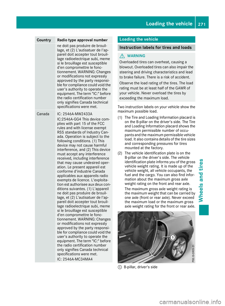
Two instruction labels on your vehicle show the maximum possible load.
(1) The Tire and LoadingI nformation placar dis
on th eB-pillar on th edriver' sside. The Tire
and LoadingI nformation placar dshows the
maximum permissible number of occu-
pant sand th emaximum permissible vehicle
load. It also contain sdetails of th etires izes
and corresponding pressures for tires
mounted at th efactory.
(2) The vehicle identification plateisont he
B-pillar on th edriver' sside. The vehicle
identification platei nformsyou of thegross
vehicle weight rating .Itismade up of the
vehicle weight,a ll vehicle occupants, the
fuel and th ecargo. You can also fin dinfor-
mation about th emaximum gross axle
weight rating on th efront and rear axle.
The maximum gross axle weight rating is
th em aximum weight that can be carried by
one axle (front or rear axle) .Never exceed
th em aximum load or th emaximum gross
axle weight rating for th efront or rear axle.
:B-pillar ,driver' sside
Loading th evehicle271
Wheels and tires
Z
Page 282 of 298
Weight of optional extras
The combined weight of those optionalextras
that weigh more than the replaced standard
parts and more than 2.3 kg (5 lbs).T hese
optionale xtras, such as high-performance
brakes ,levelc ontrol, aroof rack or ahigh-per-
formance battery,a re not included in the curb
weight and the weight of the accessories.
TIN (Tire Identification Number)
This is aunique identifier which can be use dby
at ire manufacturer to identify tires, for example
for aproduct recall, and thus identify the pur-
chasers. The TIN is made up of the manufactur-
er's identity code, tire size, tire type code and
the manufacturing date.
Load bearin gindex
The loadb earing index (also loadi ndex) isacode
that contains the maximu mloadb earing capa-
city of atire.
Traction
Tractio nisthe result of friction between the tires
and the road surface.
Treadwear indicators
Narrow bars (tread wearb ars)that are distrib-
uted over the tire tread. If the tire tread is level
with the bars ,the wearl imitofá in (1.6 mm)
has been reached.
Occupant distribution
The distribution of occupants in avehicleatt heir
designated seating positions.
Total load limit
Nominall oadand luggagel oadplus68kg
(150 lbs) multiplied by the number of seats in
the vehicle.
Changing awheel
Flat tire
The "Breakdown assistance" section
(Ypage2 46) contains information and notes on
how to dealw ithaflat tire. Informatio nondriv-
ing with MOExtended tires in the event of aflat
tire can be found under "MOExtended tires (tires
with run-fla tcharacteristics" (
Ypage2 47).
Rotating the wheels
GWARNING
Interchanging the front and rear wheels may
severely impair the driving characteristics if
the wheels or tires have different dimensions. The wheelb rakes or suspension components
may als obedamaged. There is arisk of acci-
dent.
Rotate front and rear wheels only if the wheels and tires are of the same dimensions.
!On vehicles equipped with atire pressure
monitor, electronic components are located
in the wheel.
Tire-mounting tools should not be use dnear
the valve .This coul ddamage the electronic
components.
Only have tires changed at aqualified spe-
cialist workshop.
Always pay attention to the instructions and
safety notes when changing awheel
(
Ypage2 81).
The wearp atterns on the front and rear tires
differ, depending on the operating conditions.
Rotate the wheels before aclearw earp attern
has formed on the tires. Front tires typically
wearm ore on the shoulders and the rear tires in
the center.
On vehicles that have the same size front and
rear wheels, you can rotate the wheels accord-
ing to the interval sinthe tire manufacturer's
warranty book in you rvehicled ocuments. If no
warranty book is available,t he tires should be
rotated every 3,000 to 6,000 mile s(5,000 to
10,000 km) .Depending on tire wear, this may
be required earlier. Do not change the direction
of wheelr otation.
Clean the contact surfaces of the wheela nd the
brake disc thoroughly every time awhee lisr ota-
ted. Check the tire pressure and, if necessary,
restart the tire pressure loss warning system or
the tire pressure monitor.
Directio nofrotation
Tires with aspecified direction of rotation have
additionalb enefits, e.g. if there is arisk of hydro-
planing. These advantages can only be gained if
the tires are installed corresponding to the
direction of rotation.
280Changing awheel
Wheels and tires
Page 283 of 298
An arrow on the sidewall of the tire indicates its
correct direction of rotation.
Storingwheels
Store wheels thata renot being used in acool,
dry and preferably dark place .Protect the tires
from oil, grease, gasoline and diesel.
Mounting awheel
Preparin gthe vehicle
XStop the vehicl eonsolid,non-slippery and
level ground.
XApply the electri cparking brake manually.
XBring the front wheels into the straight-ahead
position.
XShift the transmission to position j.
XSwitch off the engine.
XVehicles withoutKEYLESS -GO:remove the
SmartKeyf rom the ignition lock.
XVehicles with KEYLESS-GO: open the driv-
er' sd oor.
The vehicl eelectronics now have status 0.
Thi sist he same as the SmartKeyh aving been
removed.
XVehicles with KEYLESS-GO: remove the
Start/Stop button from the ignition lock
(
Ypage 116).
XIf included in the vehicl eequipment ,remove
the tire-change tool kit from the vehicle.
XSafeguar dthe vehicl eagain st rolling away.
iDue to difference sinvehicleequipment ,not
al lv ehicles ar eequippe dwithat ire-change
tool kit. For informatio nonwhich tool sare
required to performaw heelchange on your
vehicle, consult an authorize dMercedes-
Benz Center.
Necessary tire-changing tool scan include, for
example:
RJack
RWheel chock
RLugw rench
Securin gthe vehicle to preven titfrom
rolling away
If your vehicl eisequippe dwithaw heelchock, it
can be found in the tire-change tool kit
(
Ypage 245).
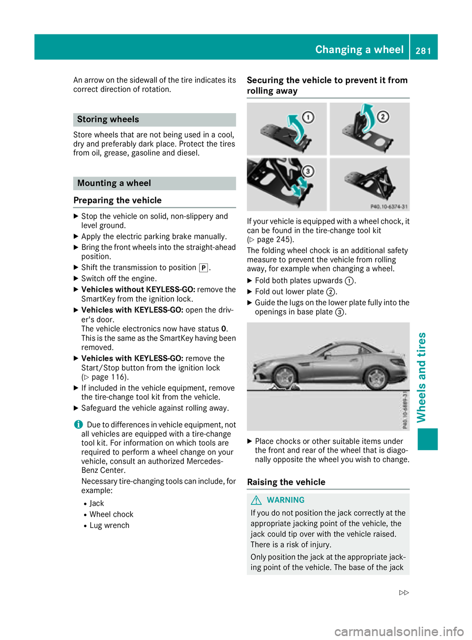
The folding whee lchoc kisana dditional safety
measure to prevent the vehicl efrom rolling
away ,for exampl ewhenc hanging awheel .
XFoldb othp late su pwar ds:.
XFoldo utlowe rplate ;.
XGuid ethe lugs on the lowe rplate full yinto the
openings in base plate =.
XPlace chocks or others uitabl eitems under
the front and rea rofthe whee lthati sdiago -
nally opposite the whee lyou wish to change.
Raisin gthe vehicle
GWARNING
If yo udon ot positio nthe jack correctl yatthe
appropriate jacking point of the vehicle, the
jack could tip overw itht he vehicl eraised.
There is ariskofi njury.
Onlyp ositiont he jack at the appropriate jack-
ing point of the vehicle. The base of the jack
Changin gawheel281
Wheel sand tires
Z
Page 284 of 298
must be positioned vertically, directly under
the jacking point of the vehicle.
!Only position the jack at the appropriate
jacking point of the vehicle. Otherwise, you
could damage the vehicle.
Observe the following when raising the vehicle:
RTo rais ethe vehicle, only use the vehicle-spe-
cific jack that has been tested and approved
by Mercedes-Benz. If used incorrectly, the
jack could tip over with the vehicler aised.
RThe jack is designed only to raiseand hold the
vehiclef oras hort time while awheelisb eing
changed. It must not be used for performing
maintenance work under the vehicle.
RAvoid changing the wheelonu phill and down-
hill slopes.
RBefore raising the vehicle, secure it from roll-
ing awa ybyapplying the parking brake and
inserting wheelc hocks. Do not disengage the
parking brake whilet he vehicleisraised.
RThe jack must be placed on afirm, flat and
non-slip surface. On aloose surface, alarge,
flat, load-bearing underlay must be used .Ona
slippery surface, anon-slip underlay must be
used ,e.g. rubber mats.
RDo not use wooden blocks or similar objects
as ajack underlay.O therwise, the jack willn ot
be abletoa chieve its load-bearing capacity
due to the restricted height.
RMake sure that the distance betweent he
underside of the tires and the ground does not
exceed 1.2 in (3 cm).
RNever place you rhands and feet under the
raised vehicle.
RDo not lie under the vehicle.
RDo not start the engine when the vehiclei s
raised.
RDo not open or close adoor or the trunk lid
when the vehicleisr aised.
RMake sure that no persons are present in the
vehiclewhen the vehicleisr aised.
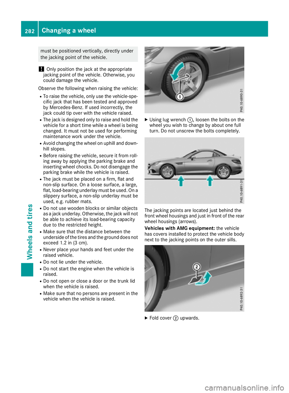
XUsing lug wrench:,loosent he bolts on the
wheely ou wish to change by abouto ne full
turn. Do not unscrew the bolts completely.
The jacking points are located just behind the
front wheelh ousings and just in front of the rear
wheelh ousings (arrows).
Vehicles with AMG equipment: the vehicle
has covers installed to protect the vehicleb ody
next to the jacking points on the outer sills.
XFold cover ;upwards.
282Changing awheel
Wheelsa nd tires
Page 286 of 298
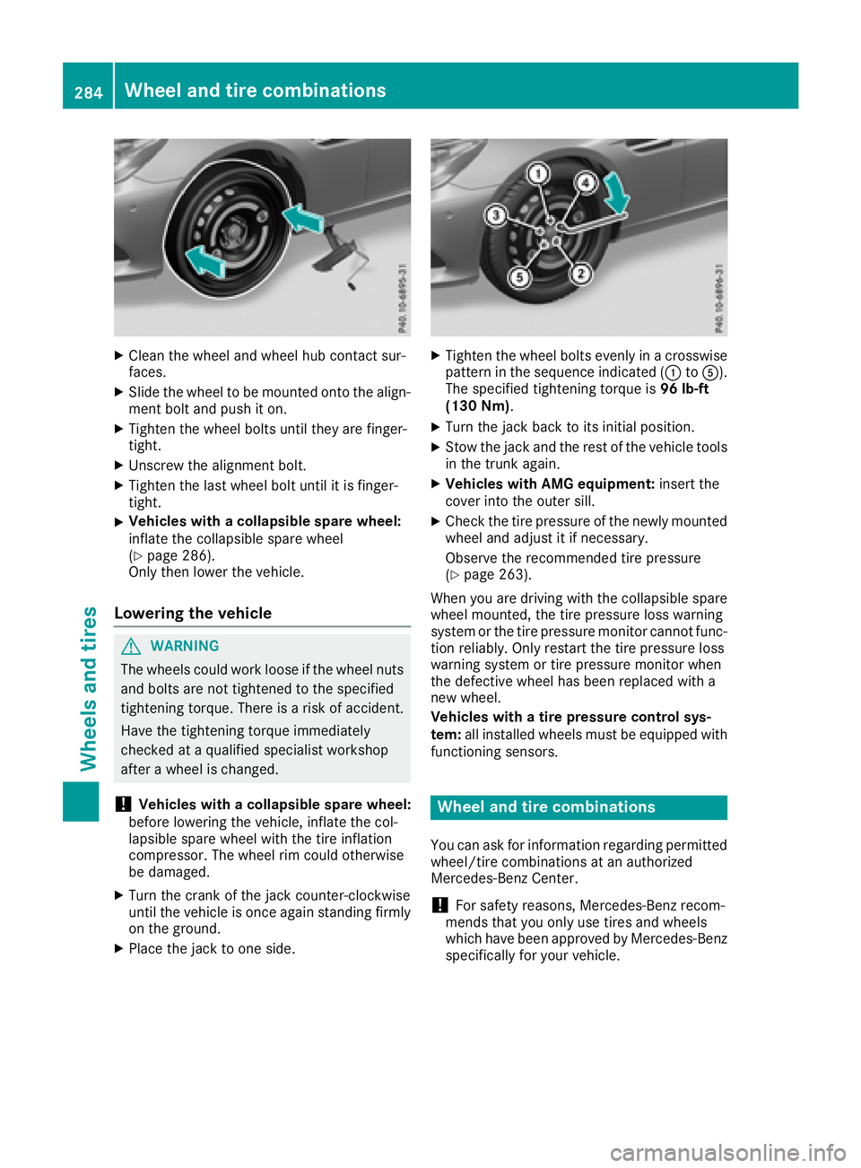
XClean thewheel and wheel hub contact sur-
faces.
XSlid ethe wheel to bemounte dontot he align-
men tbolt and push iton.
XTighte nthe wheel boltsuntilthey are finger-
tight.
XUnscrew th ealignmen tbolt.
XTighte nthe last wheel boltuntil it is finger-
tight.
XVehicles with acollapsible spa rewheel:
inflate th ecollapsible sparewheel
(
Ypage 286).
Only then lower th evehicle .
Lowering th evehicle
GWAR NING
The wheelsc ouldwork looseift hewheel nuts
and boltsare no ttightened to th especifie d
tightening torque. Thereisar iskofa cciden t.
Hav ethe tightening torque immediately
checked at aqualified specialist workshop
after awheel ischanged.
!Vehicles with acollapsible spa rewheel:
before lowering th evehicle ,inflate th ecol-
lapsible sparewheelwiththe tirei nflation
compressor. The wheel rim could otherwise
be damaged.
XTurn th ecrank of th ejackc ounter-clock wise
unt ilth ev ehicle is once again standing firmly
on th eground.
XPlacet hejacktoo neside.
XTighte nthe wheel boltse venlyinac rosswise
pattern inthes equenc eindicated (: toA).
The specifie dtightening torque is 96lb-ft
(1 30 Nm) .
XTurn th ejackb ack to its initial position.
XStow th ejac ka nd th erestoft hevehicle tools
in thet runk again.
XVehicles with AMG equipment: insert the
cover int othe outer sill.
XCheckt hetirep ressureoft henewly mounted
wheel and adjust it if necessary.
Observ ethe recommended tir epressure
(
Ypage 263).
When you are driving withthe collapsible spare
wheel mounte d,thet irep ressurel oss warning
system or th etirep ressurem onitorcanno tfunc-
tio nr eliably. Only restartthe tirep ressurel oss
warning system or tir epressurem onitorwhen
th ed efective wheel has been replace dwitha
ne ww heel.
Vehicles with atirep ressure control sys-
tem: all installed wheelsm ust be equippedwith
functioning sensors.
Wheel and tir ecombinations
You can ask for informatio nregardin gpermitted
wheel/t ire combinations at an authorized
Mercedes-Ben zCenter.
!For safety reasons, Mercedes-Ben zrecom-
men dsthat you only use tires and wheels
whichh ave been approvedbyM ercedes-Benz
specifically for your vehicle.
284Wheel and tir ecombinations
Wheels and tires