2018 MERCEDES-BENZ GLS SUV key
[x] Cancel search: keyPage 314 of 398
XLift insert:up and out.
XTo re-install the insert: place insert:into
the holder and press down on the right until it
engages.
Cigarette lighter
GWARNING
You can burn yourself if you touch the hot
heating element or the socket of the cigarette lighter.
In addition, flammable materials can ignite if:
Rthe hot cigarette lighter falls
Ra child holds the hot cigarette lighter to
objects, for example
There is a risk of fire and injury.
Always hold the cigarette lighter by the knob.
Always make sure that the cigarette lighter is
out of reach of children. Never leave children
unsupervised in the vehicle.
!The cigarette lighter in the center console in
the front compartment is not intended for
operating the tire inflation compressor.
Your attention must always be focused on the
traffic conditions. Only use the cigarette lighter
when road and traffic conditions permit.
XTurn the SmartKey to position 2in the igni-
tion lock (Ypage 140).
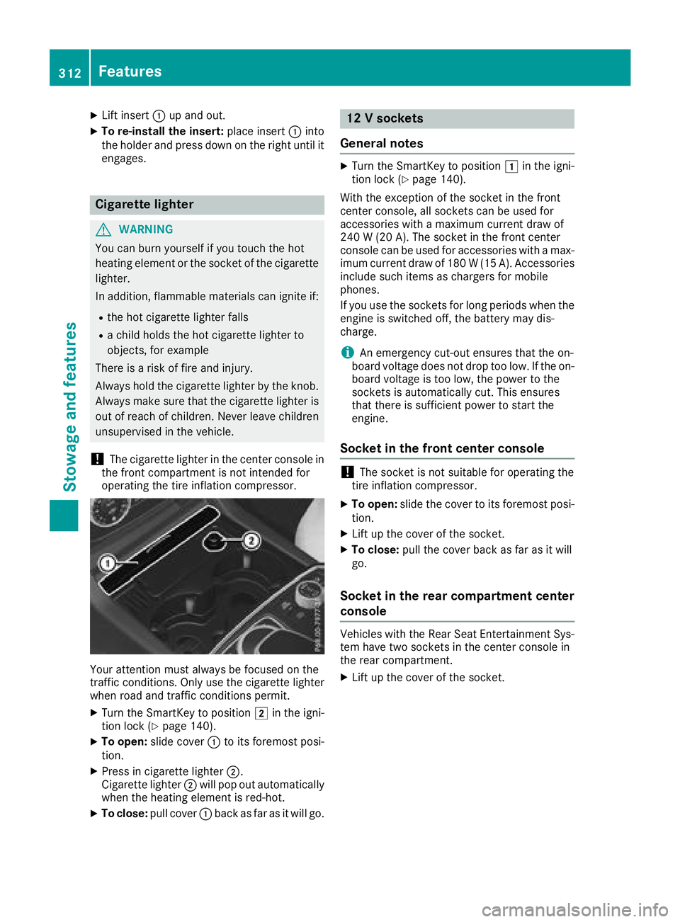
XTo open: slide cover :to its foremost posi-
tion.
XPress in cigarette lighter ;.
Cigarette lighter ;will pop out automatically
when the heating element is red-hot.
XTo close: pull cover :back as far as it will go.
12 V sockets
General notes
XTurn the SmartKey to position 1in the igni-
tion lock (Ypage 140).
With the exception of the socket in the front
center console, all sockets can be used for
accessories with a maximum current draw of
240 W (20 A). The socket in the front center
console can be used for accessories with a max-
imum current draw of 180 W(15 A). Accessories
include such items as chargers for mobile
phones.
If you use the sockets for long periods when the
engine is switched off, the battery may dis-
charge.
iAn emergency cut-out ensures that the on-
board voltage does not drop too low. If the on-
board voltage is too low, the power to the
sockets is automatically cut. This ensures
that there is sufficient power to start the
engine.
Socket in the front center console
!The socket is not suitable for operating the
tire inflation compressor.
XTo open: slide the cover to its foremost posi-
tion.
XLift up the cover of the socket.
XTo close: pull the cover back as far as it will
go.
Socket in the rear compartment center
console
Vehicles with the Rear Seat Entertainment Sys-
tem have two sockets in the center console in
the rear compartment.
XLift up the cover of the socket.
312Features
Stowage and features
Page 320 of 398
The mobile phone is no longer connected to the
multimedia system.
However, if you want to use your mobile phone,
do so only when the vehicle is stationary and in
a safe location.
Downloading destinations in COMAND
Downloading destinations
Downloading destinations gives you access to a
database with over 15 million points of interest
(POIs). These can be downloaded on the navi-
gation system in your vehicle. If you know the
destination, the address can be downloaded.
Alternatively, you can obtain the location of
Points of Interest (POIs)/important destinations
in the vicinity.
Furthermore, you can download routes with up
to four way points.
You are prompted to confirm route guidance to
the address entered.
XSelect Yesby turning 3or sliding 1
the controller and confirm with 7.
The system calculates the route and subse-
quently starts the route guidance with the
address entered.
If you select No
the address can be stored in
the address book.
The destination download function is available
if:
Rthe vehicle is equipped with a navigation sys-
tem.
Rthe relevant mobile phone network is availa-
ble and data transfer is possible.
Route Assistance
This service is part of the mbrace PLUS Package
and cannot be purchased separately.
You can use the Route Assistance function even
if the vehicle is not equipped with a navigation
system.
Within the framework of this service, you receive
a professional and reliable form of navigation
support without having to leave your vehicle.
The customer service representative finds a
suitable route depending on your vehicle's cur-
rent position and the desired destination. You
will then be guided live through the current route
section.
Search and Send
General notes
To use "Search & Send", your vehicle must be
equipped with mbrace and a navigation system.
Additionally, an mbrace service subscription
must be completed.
"Search & Send" is a service for entering desti-
nations in the navigation system. A destination
address which is found on Google Maps
®can be
transferred via mbrace directly to your vehicle's
navigation system.
Specifying and sending the destination
address
XGo to the website http://maps.google.com
and enter a destination address into the entry
field.
XTo send the destination address to the e-
mail address of your mbrace account:
click on the corresponding button on the web-
site.
Example:
If you select "Send to vehicle" and then
"Mercedes-Benz", the destination address
will be sent to your vehicle.
XWhen the "Send" dialog window appears:
Enter the e-mail address you specified when
setting up your mbrace account into the cor-
responding field.
XClick "Send".
Information on specific commands such as
"Address entry" or "Send" can be found on the
website.
Calling up a transmitted destination
address
XTurn the SmartKey to position 2in the igni-
tion lock (Ypage 140).
The transmitted destination address is loaded
into the vehicle's navigation system.
A display message appears, asking whether
navigation should be started.
XSelect Yesby turning 3or sliding 1
the controller and confirm with 7.
The system calculates the route and subse-
quently starts the route guidance with the
address entered.
If you select No
the address can be stored in
the address book.
318Features
Stowage and features
Page 321 of 398

If you have sent more than one destination
address, each individual destination must be
confirmed separately.
Destination addresses are loaded in the same
order as the order in which they were sent.
If you have multiple Mercedes-Benz vehicles
with mbrace and active mbrace accounts:
If multiple vehicles are registered under the
same e-mail address, the destination will be
sent to all the vehicles.
Vehicle remote opening
You can use the vehicle remote unlocking if you
have unintentionally locked your vehicle and a
replacement SmartKey is not available.
The vehicle can then be unlocked by the
Mercedes-Benz Customer Assistance Center.
The vehicle can be immediately unlocked
remotely within four days of the ignition being
turned off. After this time, the remote unlocking
may be delayed by 15 to 60 minutes. After
30 days, the vehicle can no longer be unlocked
remotely.
The vehicle remote unlocking feature is availa-
ble if the relevant mobile phone network is avail-
able and a data connection is possible.
XContact the following service hotlines:
Mercedes-Benz Customer Assistance Center
at 1-800 FOR-MERCEDES (1-800-367-6372)
or 1-866-990-9007
You will be asked for your password.
XReturn to your vehicle at the time agreed upon
with the Mercedes-Benz Customer Assis-
tance Center.
Alternatively, the vehicle can be opened via:
Rthe Internet, under the "Owners Online" sec-
tion
Rtelephone applications (e.g. for iPhone®,
Android™)
To do this, you will need your identification num-
ber and password.
Vehicle remote closing
The vehicle remote closing feature can be used
when you have forgotten to lock the vehicle and you are no longer nearby.
The vehicle can then be locked by the Mercedes-
Benz Customer Assistance Center. The vehicle can be immediately remotely locked
within four days of the ignition being turned off.
After this time, remote closing may be delayed
by 15 to 60 minute s.After 30 days the vehicle
can no longer be locked remotely.
The vehicle remote closing feature is available if
the relevant mobile phone network is available
and a data connection is possible.
XContact the following service hotlines:
Mercedes-Benz Customer Assistance Center
at 1-800 FOR-MERCEDES (1-800-367-6372)
or 1-866-990-9007
You will be asked for your password.
The next time you are inside the vehicle and you
switch on the ignition, the Doors Locked
Remotelymessage appears in the multifunction
display.
Alternatively, the vehicle can be locked via:
Rthe Internet, under the "Owners Online" sec-
tion
Rtelephone applications (e.g. for iPhone®,
Android™)
To do this, you will need your identification num-
ber and password.
Stolen vehicle recovery service
If your vehicle has been stolen:
XNotify the police.
The police will issue a numbered incident
report.
XForward this number to the Mercedes-Benz
Customer Assistance Center along with your
PIN.
The Mercedes-Benz Customer Assistance
Center then tries to locate the system. The
Mercedes-Benz Customer Assistance Center
contacts you and the local law enforcement
agency if the vehicle is located.
However, only the law enforcement agency is
informed of the location of the vehicle.
If the anti-theft alarm system is activated for
longer than 30 seconds, mbrace automatically
notifies the Mercedes-Benz Customer Assis-
tance Center.
Vehicle Health Check
With the Vehicle Health Check, the Customer
Assistance Center can provide improved sup-
port for problems with your vehicle. During an
Features319
Stowage and features
Z
Page 322 of 398
existing call, vehicle data is transferred to the
Customer Assistance Center.
The customer service representative can use
the received data to decide what kind of assis-
tance is required. You are then, for example,
guided to the nearest Mercedes-Benz Service
Center or a recovery vehicle is called.
If vehicle data need to be transferred during an
Info call or a Roadside Assistance call, this is
initiated by the Customer Assistance Center.
TheRoadside Assistance Connected
mes-
sage appears in the display. If the Vehicle Health
Check can be started, the Request
forVehi‐cle Diagnostics Received Start vehi‐cle diagnostics?message appears in the
display.
XPress the Yesbutton to confirm the message.
XIf theVehicle Diagnostics PleaseStart Ignitionmessage appears: turn the
SmartKey to key position 2in the ignition
lock (
Ypage 140).
XIf the Please follow the instructionsreceivedbyphoneandmoveyourvehi‐cle to a safe position.message
appears: please follow the instructions
received by phone and move your vehicle to a
safe position.
The message in the display disappears.
The vehicle operating state check begins.
During this procedure, you will see the Vehi‐
cle Diagnostics Activemessage.
If you select Cancel
, the Vehicle Health
Check is canceled completely.
When the check is complete, the Sending
vehicle diagnostics data. (Voice con‐nection may be interrupted duringdatatransfer)message appears. The vehicle
data can now be sent.
XPress the OKbutton to confirm the message.
The voice connection with the Customer
Assistance Center is terminated.
The Vehicle Diagnostics: Transfer‐
ring Data...message appears.
The vehicle data is sent to the Customer
Assistance Center.
Depending on what the customer service rep-
resentative agreed with you, the voice connec-
tion is re-established after the transfer is com-
plete. If necessary, you will be contacted at a
later time by another means, e.g. by e-mail or
phone. Another function of the Vehicle Health Check is
the transfer of service data to the Customer
Assistance Center. If a service is due, the display
shows a message to this effect together with
information about any special offers at your
workshop.
This information can also be called up under
"Owners Online" at
http://www.mbusa.com.
Information on the data stored in the vehicle
(
Ypage 32).
Information on Roadside Assistance
(
Ypage 29).
Downloading routes
Downloading routes allows you to transfer and
save predefined routes in the navigation sys-
tem.
A route can be prepared and sent either by a
customer service representative or under "Own-
ers Online" at http://www.mbusa.com.
Each route can include up to four way points.
Once a route has been received by the naviga-
tion system, you will see the Do
youwanttostart route guidance? DestinationReceived destination has been savedin "Previous destinations".message on
the multimedia system display.
The route is saved.
XTo start route guidance: selectYes.
An overview of the route is shown in the dis-
play.
If you select No
, the saved route can be called
up later in the navigation menu.
XSelect Start.
Route guidance starts.
Downloaded and saved routes can be called up
again.
Speed alert
You can define the upper speed limit, which
must not be exceeded by the vehicle.
If the vehicle exceeds the set speed, a message
is sent to the Customer Assistance Center. The
Customer Assistance Center then forwards this
information to you.
You can select the way in which you receive this
information beforehand. Possible options
include text message, e-mail or an automated
call.
320Features
Stowage and features
Page 324 of 398

Programming
Programming the buttons
Pay attention to the "Important safety notes"
(Ypage 321).
Garage door remote controlAis not included
with the integrated garage door opener.
XTurn the SmartKey to position 2in the igni-
tion lock (Ypage 140).
XSelect one of buttons ;to? to use to con-
trol the garage door drive.
XTo start programming mode: press and
hold one of buttons ;to? on the integrated
garage door opener.
The garage door opener is now in program-
ming mode. After a short time, indicator
lamp :lights up yellow.
Indicator lamp :lights up yellow as soon as
button ;,=or? is stored for the first time.
If the selected button has already been pro-
gramed, indicator lamp :will only light up
yellow after ten seconds have elapsed.
XRelease button ;,=or?. Indicator
lamp :flashes yellow.
XTo program the remote control: point
garage door remote control Atowards but-
tons ;to? on the rear-view mirror at a dis-
tance of 2 to 8 in (5 to 20 cm).
XPress and hold button Bon remote control
A until indicator lamp :lights up green.
When indicator lamp :lights up green: pro-
gramming is finished.
When indicator lamp :flashes green: pro-
gramming was successful. The next step is to synchronize the rolling code (
Ypage 322).
XRelease button Bon remote control Afor
the garage door drive system.
If indicator lamp :lights up red: repeat the
programing procedure for the corresponding
button on the rear-view mirror. When doing so, vary the distance between remote control
A
and the rear-view mirror.
The required distance between remote con-
trol Aand the integrated garage door opener
depends on the garage door drive system.
Several attempts might be necessary. You
should test every position for at least
25 seconds before trying another position.
Synchronizing the rolling code
Pay attention to the "Important safety notes"
(Ypage 321).
If the garage door system uses a rolling code,
you will also have to synchronize the garage
door system with the integrated garage door
opener in the rear-view mirror. To do this you will
need to use the programming button on the door
drive control panel. The programming button
may be located in different places depending on
the manufact
urer. It is usually located on the
door drive unit on the garage ceiling.
Familiarize yourself with the garage door drive
operating instructions, e.g. under "Program-
ming additional remote controls", before carry-
ing out the following steps.
Your vehicle must be within reach of the garage
door or gate opener drive. Make sure that nei-
ther your vehicle nor any persons/objects are
present within the sweep of the door or gate.
XTurn the SmartKey to position 2in the igni-
tion lock (Ypage 140).
XGet out of the vehicle.
XPress the programming button on the door
drive unit.
You now have 30 seconds to initiate the next
step.
XGet into the vehicle.
XPress previously programed button ;,=
or ? on the integrated garage door opener
repeatedly until the door closes.
The rolling code synchronization is then com- plete.
Notes on programming the remote con-
trol
Canadian radio frequency laws require a "break"(or interruption) of the transmission signals
after broadcasting for a few seconds. Therefore,
these signals may not last long enough for the
integrated garage door opener. The signal is not recognized during programming. Comparable
322Features
Stowage and features
Page 325 of 398
with Canadian law, some U.S. garage door open-
ers also feature a "break".
Proceed as follows:
Rif you live in Canada.
Rif you have difficulties programming the
garage door opener (regardless of where youlive) when following the programming steps.
XPress and hold one of buttons ;to? on the
integrated garage door opener.
After a short time, indicator lamp :lights up
yellow.
XRelease the button.
Indicator lamp :flashes yellow.
XPress button Bof garage door remote con-
trol Afor two seconds, then release it for two
seconds.
XPress button Bagain for two seconds.
XRepeat this sequence on button Bof remote
control Auntil indicator lamp :lights up
green.
When indicator lamp :lights up green: pro-
gramming is finished.
When indicator lamp :flashes green: pro-
gramming was successful. The next step is to
synchronize the rolling code.
XRelease button Bof remote control Aof the
garage door drive.
When indicator lamp :lights up red: repeat
the programming process for the correspond-
ing button on the rear-view mirror. When
doing so, vary the distance between remote
control Aand the rear-view mirror.
The required distance between remote con-
trol Aand the integrated garage door opener
depends on the garage door drive system.
Several attempts might be necessary. You
should test every position for at least
25 seconds before trying another position.
Problems when programming
If you are experiencing problems programming
t
he integrated garage door opener on the rear-
view mirror, take note of the following instruc-
tions:
RCheck the transmitter frequency used by
garage door drive remote control Aand
whether it is supported. The transmitter fre-
quency can usually be found on the back of
remote control Afor the garage door drive.
The integrated garage door opener is com-
patible with devices that have units which operate in the frequency range of 280 to
433 MHz.
RReplace the batteries in garage door remote
control
A. This increases the likelihood that
garage door remote control Awill transmit a
strong and precise signal to the integrated
garage door opener.
RWhen programming, hold remote control A
at varying distances and angles from but-
tons ;to? which you are programming. Try
various angles at a distance between 2and
8 inches (5to 20 cm) or at the same angle but
at varying distances.
RIf a further remote control Ais available for
the same garage door drive, repeat the same
programming steps with this remote control
A. Before performing these steps, make sure
that new batteries have been installed in
garage door drive remote control A.
RNote that some remote controls only transmit
for a limited amount of time (the indicator
lamp on the remote control goes out). Press
buttonBon remote control Aagain before
transmission ends.
RAlign the antenna cable of the garage door
opener unit. This can improve signal recep-
tion/transmission.
Opening/closing the garage door
After it has been programmed, the integrated
garage door opener performs the function of the
garage door system remote control. Please also
read the operating instructions for the garage
door system.
XTurn the SmartKey to position 2in the igni-
tion lock (Ypage 140).
XPress button ;,=or? which you pro-
grammed to operate the garage door.
Garage door system with a fixed code: indi-
cator lamp :lights up green.
Garage door system with a rolling code: indi-
cator lamp :flashes green.
The transmitter will transmit a signal as long
as the button is pressed. The transmission is
halted after a maximum of ten seconds and
indicator lamp :lights up yellow.
XPress button ;,=or? again if necessary.
Features323
Stowage and features
Z
Page 326 of 398
Clearing the memory
Make sure that you clear the memory of the
integrated garage door opener before selling the
vehicle.
XTurn the SmartKey to position2in the igni-
tion lock (Ypage 140).
XPress and hold buttons ;and ?.
Indicator lamp :initially lights up yellow and
then green.
XRelease buttons ;and ?.
The memory of the integrated garage door
opener in the rear-view mirror is cleared.
Floormats
GWARNING
Objects in the driver's footwell can restrict the pedal travel or obstruct a depressed pedal.
The operating and road safety of the vehicle is
jeopardized. There is a risk of an accident.
Make sure that all objects in the vehicle are
stowed correctly, and that they cannot enter
the driver's footwell. Install the floormats
securely and as specified in order to ensure
sufficient clearance for the pedals. Do not use
loose floormats and do not place floormats on
top of one another.
XDriver's seat/front-passenger seat: slide
the respective seat back.
XRear seats: slide the corresponding front
seat forwards.
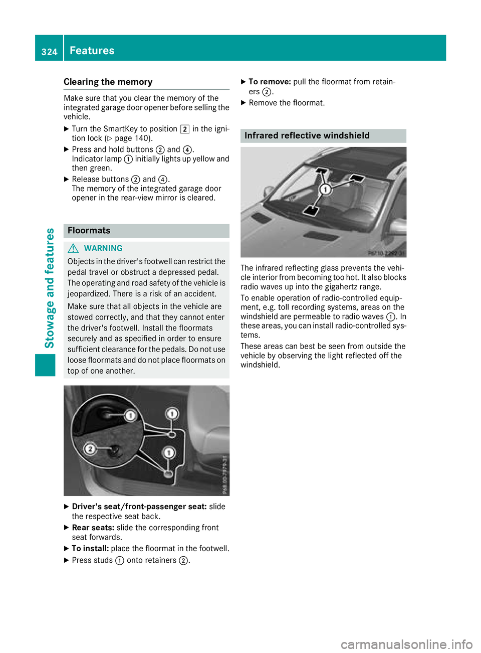
XTo install: place the floormat in the footwell.
XPress studs :onto retainers ;.
XTo remove:pull the floormat from retain-
ers ;.
XRemove the floormat.
Infrared reflective windshield
The infrared reflecting glass prevents the vehi-
cle interior from becoming too hot. It also blocks
radio waves up into the gigahertz range.
To enable operation of radio-controlled equip-
ment, e.g. toll recording systems, areas on the
windshield are permeable to radio waves :. In
these areas, you can install radio-controlled sys-
tems.
These areas can best be seen from outside the
vehicle by observing the light reflected off the
windshield.
324Features
Stowage and features
Page 330 of 398
Further information on engine oil (Ypage 389).
Additional service products
Important safety notes
GWARNING
Certain components in the engine compart-
ment, such as the engine, radiator and parts
of the exhaust system, can become very hot.
Working in the engine compartment poses a
risk of injury.
Where possible, let the engine cool down and touch only the components described in the
following.
GWARNING
The cooling system is pressurized, particularly
when the motor is warm. If you open the cap,
you could be scalded if hot coolant sprays out.
There is a risk of injury.
Let the engine cool down before you open the
cap. Wear gloves and eye protection. Slowly
open the cap to relieve pressure.
The coolant level may only be checked and cool-
ant refilled when the engine and engine cooling
system have cooled down.
GWARNING
Windshield washer concentrate could ignite if it comes into contact with hot engine compo-
nents or the exhaust system. There is a risk of
fire and injury.
Make sure that no windshield washer con-
centrate is spilled next to the filler neck.
Checking coolant level
XPark the vehicle on a level surface.
Only check the coolant level when the vehicleis on a level surface and the engine has cooled
down.
XTurn the SmartKey to position 2in the igni-
tion lock (Ypage 140).
On vehicles with KEYLESS-GO, press the
Start/Stop button twice (
Ypage 142).
XCheck the coolant temperature gauge in the
multifunction display.
The coolant temperature must be below
158 ‡ (70 †).
XTurn the SmartKey to position in the ignition
lock u(Ypage 140).
XOn vehicles with KEYLESS-GO, press the
Start/Stop button (Ypage 142).
XPress the Start/Stop button (Ypage 142).
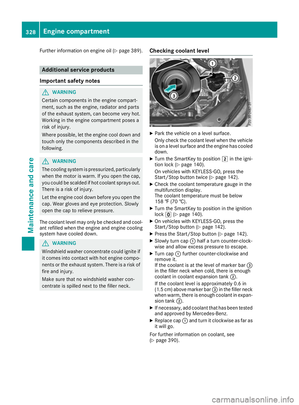
XSlowly turn cap :half a turn counter-clock-
wise and allow excess pressure to escape.
XTurn cap :further counter-clockwise and
remove it.
If the coolant is at the level of marker bar =
in the filler neck when cold, there is enough
coolant in coolant expansion tank ;.
If the coolant level is approximately 0.6 in
(1.5 cm) above marker bar =in the filler neck
when warm, there is enough coolant in expan-
sion tank ;.
XIf necessary, add coolant that has been tested
and approved by Mercedes-Benz.
XReplace cap :and turn it clockwise as far as
it will go.
For further information on coolant, see
(
Ypage 390).
328Engine compartment
Maintenance and care