2018 MERCEDES-BENZ GLE SUV technical specifications
[x] Cancel search: technical specificationsPage 197 of 398

The flap closes again when:
Ryou have finished the maneuvering process
Ryou switch off the engine
Ryou open the cargo compartment
Observe the notes on cleaning (
Ypage 330).
For technical reasons, the flap may remain
open briefly after the rear view camera has
been deactivated.
Activating/deactivating the rear view
camera
XTo activate: make sure that the SmartKey is
in position 2in the ignition lock.
XMake sure that the Activation by R gearfunction is selected in the multimedia system
(see the Digital Operator's Manual).
XEngage reverse gear.
The rear view camera flap opens. The multi-
media system shows the area behind the vehi-
cle with guide lines.
The image from the rear view camera is avail-
able throughout the maneuvering process.
XTo switch the function mode for vehicles
with trailer tow hitch: using the controller,
select symbol :for the "Reverse parking"
function or symbol ;for "Coupling up a
trailer".
The symbol of the selected function is high-
lighted.
To deactivate: the rear view camera deacti-
vates if you shift the transmission to jor after
driving forwards a short distance.
Displays in the multimedia system
The rear view camera may show a distorted view
of obstacles, show them incorrectly or not at all.
The rear view camera does not show objects in
the following positions:
Rvery close to the rear bumper
Runder the rear bumper
Rin the area immediately above the tailgate
handle
!Objects not at ground level may appear to
be further away than they actually are, e.g.:
Rthe bumper of a parked vehicle
Rthe drawbar of a trailer
Rthe ball coupling of a trailer tow hitch
Rthe rear section of an HGV
Ra slanted post
Use the guidelines only for orientation.
Approach objects no further than the bottom-
most guideline.
:Yellow guide line at a distance of approx-
imately 13 ft (4.0 m) from the rear of the
vehicle
;White guide line without turning the steering
wheel, vehicle width including the exterior
mirrors (static)
=Yellow guide line for the vehicle width
including the exterior mirrors, for current
steering wheel angle (dynamic)
?Yellow lane marking the course the tires will
take at the current steering wheel angle
(dynamic)
AYellow guide line at a distance of approx-
imately 3 ft (1.0 m) from the rear of the vehi-
cle
BVehicle center axle (marker assistance)
CBumper
DRed guide line at a distance of approximately
12 in (0.30 m) from the rear of the vehicle
The guide lines are shown when the transmis-
sion is in position k.
The distance specifications only apply to
objects that are at ground level.
Driving systems195
Driving and parking
Z
Page 200 of 398

iFor technical reasons, the ball coupling of
the trailer tow hitch in the multimedia system
display is either only partially visible or not at
all.
XSelect symbol ?using the controller.
The "Coupling up a trailer" function is selec-
ted. The distance specifications now only
apply to objects that are at the same level as
the ball coupling.
XBack up carefully, making sure that trailer
drawbar locating aid ;points approximately
in the direction of trailer drawbar =.
XBack up carefully until trailer drawbar =rea-
ches the red guide line.
The distance between the trailer drawbar and the red guide line is now approximately
0.30 m.
XCoupl eup the trailer (Ypage 220).
180° view
:Symbol for the 180° view function
;Your vehicle
=Warning displays for Parking Assist
PARKTRONIC
You can also use the rear view camera to select
a 180° view.
When Parking Assist PARKTRONIC is opera-
tional (
Ypage 188), a symbol for your own vehi-
cle appears in the multimedia system. If the
Parking Assist PARKTRONIC warning displays
are active, warning displays =light up in the
multimedia system in yellow or red accordingly.
360° camera
General notes
The 360° camera is a system consisting of four
cameras.
The system processes images from the follow-
ing cameras:
RRear view camera
RFront camera
RTwo cameras in the exterior rear view mirrors
The cameras cover the immediate surroundings
of the vehicle. The 360° camera assists you, for
instance when parking or at exits with reduced
visibility.
You can show pictures from the 360° camera in
full-screen mode or in seven different split-
screen views on the multimedia system display.
A split-screen view also includes a top view of
the vehicle. This view is calculated from the data
supplied by the installed cameras (virtual cam-
era).
The six split-screen views are:
RTop view and picture from the rear view cam-
era (130° viewing angle)
RTop view and image from the front camera
(130° viewing angle without displaying the
maximum steering wheel angle)
RTop view and enlarged rear view
RTop view and enlarged front view
RTop view and trailer view (vehicles with trailer
tow hitch)
RTop view and rear-view images from the exte-
rior mirror cameras (rear wheel view)
RTop view and forward-view images from the
exterior mirror cameras (front wheel view)
When the function is active and you shift the
transmission from hork toi, the dynamic
guide lines are hidden.
When you shift between transmission positions
h and k, you see the previously selected front
or rear view.
Distances measured by Parking Assist
PARKTRONIC will also be optically displayed:
Rin split screen view as red or yellow brackets
around the vehicle icon in the top view, or
Rat the bottom right as red or yellow brackets
around the vehicle symbol in full-screen mode
The line thickness and color of the brackets
show how far the vehicle is away from an object:
198Driving system s
Driving an d parking
Page 226 of 398

Decouplingatrailer
GWARNING
If you uncoupl e atrailer wit hth eoverrun
brake engaged, you could trap your han d
between th evehicle and th etrailer drawbar .
There is aris kof injury.
Do no tuncoupl e atrailer if th eoverrun brake
is engaged.
GWARNING
Vehicles wit hlevel control:
The vehicle is lowered as soo nas you discon-
nect th etrailer cable. Thi scould result in your
limbs or those of other people that are
between th evehicle bod yand tires or under-
neat hth evehicle bein gtrapped. There is a
ris kof injury.
Mak esur ethat nobod yis in th eimmediate
vicinit yof th ewhee lhousings or under th e
vehicle when you disconnec tth etrailer cable.
!Do no tdisconnec t atrailer wit han engage d
overrun brake .Otherwise ,your vehicle could
be damaged by th ereboundin gof th eoverrun
brake .
XShift th etransmissio nto position P.
XApply thevehicle' selectric parking brake .
XStart theengine.
XClos eth edoors and tailgate.
XApply th etrailer's parking brake .
XDetach thetrailer cable and decoupl eth e
trailer .
XSwitchof fth eengine.
Permissible trailer loads an ddrawbar
loads
Weight specifications
Maximum allowable gross mass
The gross vehicle weight of th etrailer is calcu-
lated by addin gth eweight of th etrailer to th e
weight of th eload and equipmen ton th etrailer .
You will fin dinstallin gdimensions and load s
under "Technical data" (
Ypage 394).
Permissible noseweigh t
You will findinstallin gdimensions and load s
under "Technical data" (Ypage 394).
Loadingatrailer
RWhe nloadin gth etrailer ,mak esur ethat nei-
ther th epermissible gross weight of th etrailer
no rth egross vehicle weight are exceeded.
The permissible gross vehicle weight is indi-
cated on th eidentification plat elocated on
th eB-pilla ron th edriver's sid eof th evehicle.
You can fin dth emaximum permissible values
on th etyp eplates of your vehicle and th e
trailer .Whe ncalculatin ghow muc hweight
th evehicle and trailer may carry, pay atten-
tion to th erespective lowest values.
RThe trailer drawbar load on th eball couplin g
mus tbe adde dto th erea raxl eload to avoid
exceedin gth epermissible gross axl eweight .
The permissible gross vehicle weight is indi-
cated on th eidentification plat elocated on
th eB-pilla ron th edriver's sid eof th evehicle.
iMercedes-Ben zrecommends atrailer load
wher eth etrailer drawbar noseweigh t
accounts fo r 8 %to 15 %of th etrailer's per -
missible gross weight .
iThe weight of additional accessories ,pas-
sengers, and cargo reduce sth epermissible
trailer load and drawbar load fo ryour vehicle.
Checking th evehicle an dtrailer weigh t
RTo checkthat th eweight sof th etowin gvehi-
cl e and th etrailer compl ywit hth emaximum
permissible values, hav eth evehicle/trailer
combination (includin gth edriver ,passen -
gers, and cargo wit h afullylade ntrailer )
weighed on acalibrated weighbridge .
RCheckth egross axl eweight ratin gof th efron t
and rea raxles, th egross weight of th etrailer
and th etrailer drawbar noseweight.
Removin gth eball coupling
XRemov eth esprin gcotter.
XRemov eth ebolt from th eball couplin g
recess .
XRemov eth eball couplin gfrom th eball cou-
plin grecess .
224Towing a trailer
Driving and parking
Page 390 of 398

ModelCapacity
GLE 550 4MATIC
Mercedes-AMG
GLE 63 4MATIC
Mercedes-AMG
GLE 63 S 4MATIC9.0 US qt (8.5l)
Allot her models7.4 US qt (7.0 l)
Additives
!Do not use any additives in the engine oil.
This could damage the engine.
Brake fluid
GWARNING
The brake fluid constantly absorbs moisture
from the air. This lowers the boiling point of
the brake fluid. If the boiling point of the brake
fluid is too low, vapor pockets may form in the
brake system when the brakes are applied
hard. This would impair braking efficiency.
There is a risk of an accident.
You should have the brake fluid renewed at
the specified intervals.
Comply with the important safety notes for ser-
vice products when handling brake fluid
(
Ypage 383).
Only use brake fluid approved for Mercedes-
Benz according to MB-Freigabe or MB-Approval
331.0.
Information about approved brake fluid can be
obtained at any qualified specialist workshop or on the Internet at
http://bevo.mercedes-benz.com.
iHave the brake fluid regularly replaced at a
qualified specialist workshop in accordance
with the replacement intervals and the
replacement confirmed in the service report.
Coolant
Important safety notes
GWARNING
If antifreeze comes into contact with hot com- ponents in the engine compartment, it may
ignite. There is a risk of fire and injury.
Let the engine cool down before you add anti-
freeze. Make sure that antifreeze is not spilled
next to the filler neck. Thoroughly clean the
antifreeze from components before starting
the engine.
!Only add coolant that has been premixed
with the desired antifreeze protection. You
could otherwise damage the engine.
Further information on coolants can be found
in the Mercedes-Benz Specifications for Ser-
vice Products, MB BeVo 310.1, e.g. on the
Internet at
http://bevo.mercedes-benz.com. Or con-
tact a qualified specialist workshop.
!Always use a suitable coolant mixture, even
in countries where high temperatures prevail.
Otherwise, the engine cooling system is not
sufficiently protected from corrosion and
overheating.
iHave the coolant regularly replaced at a
qualified specialist workshop and the replace-
ment confirmed in the service report.
Comply with the important safety notes for ser-
vice products when handling coolant
(
Ypage 383).
The coolant is a mixture of water and anti-
freeze/corrosion inhibitor. It is responsible for
the following:
Ranti-corrosion protection
Rantifreeze protection
Rraising the boiling point
If the coolant has antifreeze protection dow n to
-35 ‡ (
-37 †), the boiling point of the coolant
during operation is approximately 266 ‡
(130 †).
388Service products and filling capacities
Technical data
Page 391 of 398

The antifreeze concentrate/corrosion inhibitor
concentration in the engine cooling system
should:
Rbe at least 50%. This will protect the engine
cooling system against freezing down to
approximately -35 ‡ (-37 †).
Rnot exceed 55% (antifreeze protection down
to -49‡[-45 †]). Otherwise, heat will not be
dissipated as effectively.
Mercedes-Benz recommends an antifreeze/
corrosion inhibitor concentrate in accordance
with MB Specifications for Service Products
310.1.
iWhen the vehicle is first delivered, it is filled
with a coolant mixture that ensures adequate
antifreeze and anti-corrosion protection.
iThe coolant is checked at specified intervals
at a qualified specialist workshop.
Filling capacities
Missing values were not available at time of
going to print.
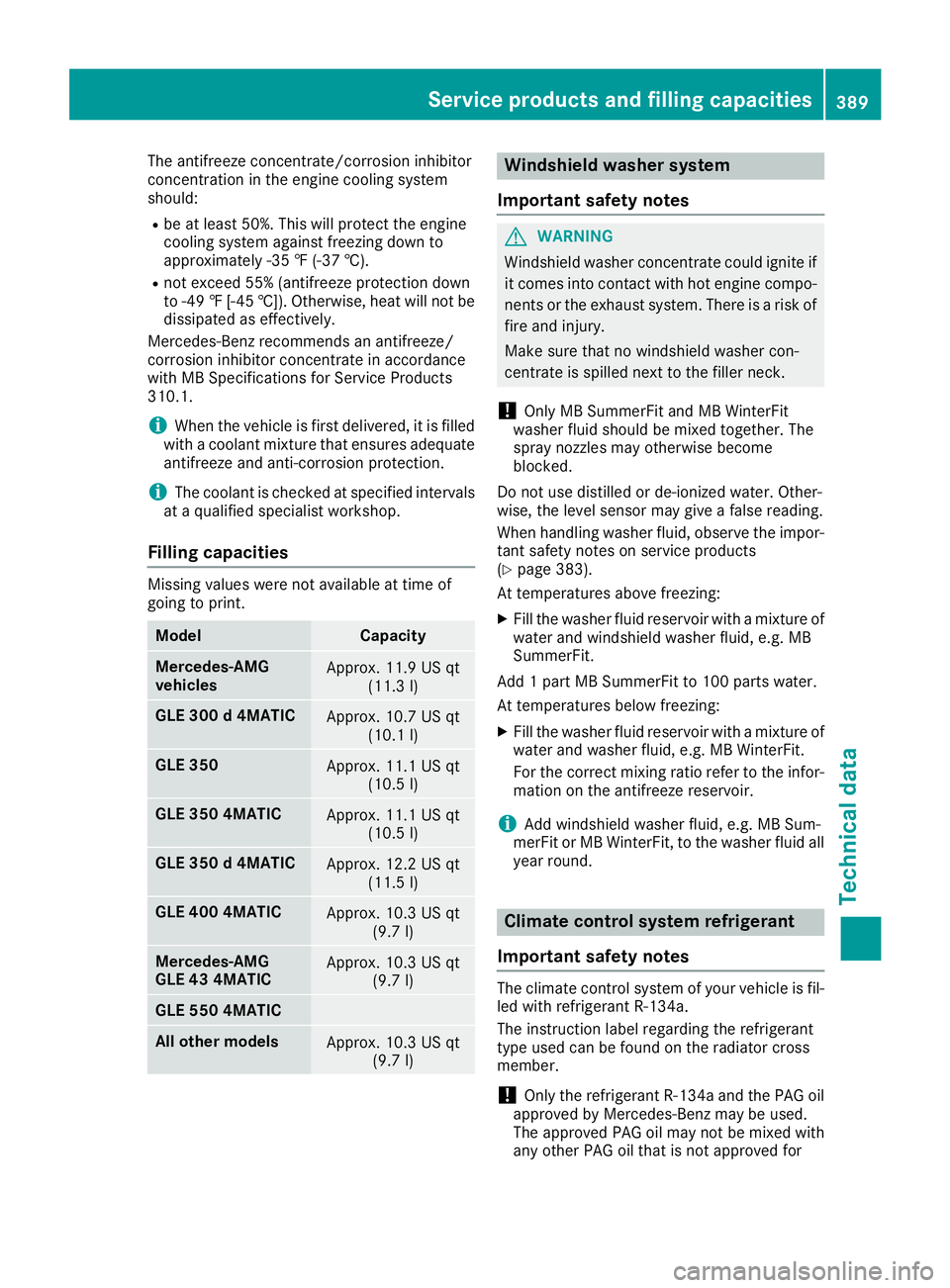
ModelCapacity
Mercedes ‑AMG
vehiclesApprox. 11.9 US qt (11.3l)
GLE 300 d 4MATICApprox. 10.7 US qt
(10.1l)
GLE 350Approx. 11.1 US qt
(10.5l)
GLE 350 4MATICApprox. 11.1 US qt
(10.5l)
GLE 350 d 4MATICApprox. 12.2 US qt
(11.5l)
GLE 400 4MATICApprox. 10.3 US qt
(9.7 l)
Mercedes-AMG
GLE 43 4MATICApprox. 10.3 US qt(9.7 l)
GLE 550 4MATIC
All other modelsApprox. 10.3 US qt(9.7 l)
Windshield washer system
Important safety notes
GWARNING
Windshield washer concentrate could ignite if it comes into contact with hot engine compo-
nents or the exhaust system. There is a risk of
fire and injury.
Make sure that no windshield washer con-
centrate is spilled next to the filler neck.
!Only MB SummerFit and MB WinterFit
washer fluid should be mixed together. The
spray nozzles may otherwise become
blocked.
Do not use distilled or de-ionized water. Other-
wise, the level sensor may give a false reading.
When handling washer fluid, observe the impor-
tant safety notes on service products
(
Ypage 383).
At temperatures above freezing:
XFill the washer fluid reservoir with a mixture of
water and windshield washer fluid, e.g. MB
SummerFit.
Add 1 part MB SummerFit to 100 parts water.
At temperatures below freezing:
XFill the washer fluid reservoir with a mixture of
water and washer fluid, e.g. MB WinterFit.
For the correct mixing ratio refer to the infor-
mation on the antifreeze reservoir.
iAdd windshield washer fluid, e.g. MB Sum-
merFit or MB WinterFit, to the washer fluid all
year round.
Climate control system refrigerant
Important safety notes
The climate control system of your vehicle is fil-
led with refrigerant R ‑134a.
The instruction label regarding the refrigerant
type used can be found on the radiator cross
member.
!Only the refrigerant R ‑134a and the PAG oil
approved by Mercedes-Benz may be used.
The approved PAG oil may not be mixed with
any other PAG oil that is not approved for
Service products and filling capacities389
Technical data
Z