2018 MERCEDES-BENZ GLE SUV sport mode
[x] Cancel search: sport modePage 348 of 398

driver's or front-passenger door, which could
damage the transmission.
!Do not tow with sling-type equipment. This
could damage the vehicle.
!Vehicles with differential locks: make sure
the differential locks are in automatic mode.
When towing, the differential locks must not
be switched on. The transmission may other-
wise be damaged.
!The vehicle can be towed a maximum of
30 miles (50km). The towing speed of 30 mph (50 km/h) must not be exceeded.
If the vehicle has to be towed more than
30 miles (50km), the entire vehicle must be
raised and transported.
It is better to have the vehicle transported than
to have it towed away.
If the vehicle has suffered transmission damage,
have it transported on a transporter or trailer.
The automatic transmission must be in position
i when the vehicle is being towed.
The battery must be connected and charged.
Otherwise, you:
Rcannot turn the SmartKey to position 2in
the ignition lock
Rcannot release the electric parking brake
Rcannot shift the automatic transmission to
position i
Disarm the automatic locking feature before the vehicle is towed (
Ypage 239). You could other-
wise be locked out when pushing or towing the
vehicle.
If the vehicle is in a dangerous area, it can be
towed out of that area with both axles on the
ground. In this case, the towing distance must
not be greater than 165 ft (50 m)and must not
exceed a towing speed of 6 mph (10 km/h). For
longer distances, have the vehicle loaded and
transported.
Installing/removing the towing eye
Installing the towing eye
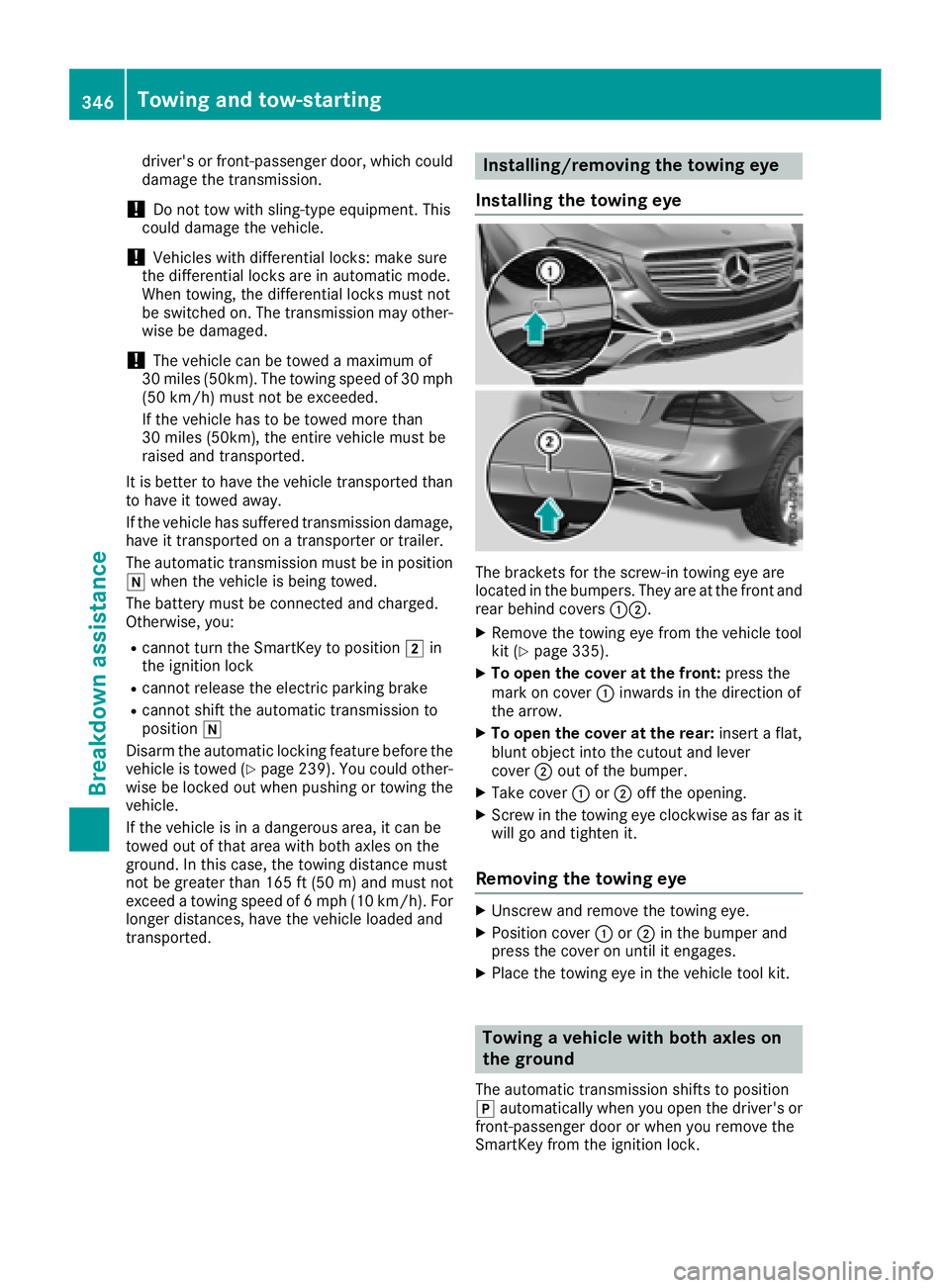
The brackets for the screw-in towing eye are
located in the bumpers. They are at the front and
rear behind covers :;.
XRemove the towing eye from the vehicle tool
kit (Ypage 335).
XTo open the cover at the front: press the
mark on cover :inwards in the direction of
the arrow.
XTo open the cover at the rear: insert a flat,
blunt object into the cutout and lever
cover ;out of the bumper.
XTake cover :or; off the opening.
XScrew in the towing eye clockwise as far as it
will go and tighten it.
Removing the towing eye
XUnscrew and remove the towing eye.
XPosition cover :or; in the bumper and
press the cover on until it engages.
XPlace the towing eye in the vehicle tool kit.
Towing a vehicle with both axles on
the ground
The automatic transmission shifts to position
j automatically when you open the driver's or
front-passenger door or when you remove the
SmartKey from the ignition lock.
346Towing and tow-starting
Breakdown assistance
Page 356 of 398

To avoid hazardous situations:
Rnever install snow chains to the front
wheels
Ralways install snow chains in pairs to the
rear wheels.
!Check the snow chains for damage before
mounting them. Damaged or worn snow
chains may snap and damage the following
components:
Rwheel
Rwheel housing
Rwheel suspension
For this reason, you must use only snow
chains that are free of defects. Observe the
manufacturer's mounting instructions.
!You must drive at raised vehicle level (height
1) if snow chains have been installed. The
vehicle may otherwise be damaged.
!Vehicles with ADS (Adaptive Damping
System): do not use the sport mode when
driving with snow chains mounted. The vehi-
cle may otherwise be damaged.
For safety reasons, Mercedes-Benz recom-
mends that you only use snow chains that have
been specially approved for your vehicle by
Mercedes-Benz, or are of a corresponding
standard of quality. For more information,
please contact a qualified specialist workshop.
Install the snow chains on all driven wheels for
maximum tractive power and driving stability. If
you own snow chains for two driven wheels only,
install the snow chains to the wheels on the rear
axle. The vehicle then remains more stable
under braking.
If you intend to mount snow chains, please bear
the following points in mind:
RSnow chains may not be mounted on all
wheel/tire combinations. Permissible
wheel/tire combinations (
Ypage 376).
ROnly use snow chains when driving on roads
completely covered by snow. Remove the
snow chains as soon as possible when you
come to a road that is not snow-covered.
RLocal regulations may restrict the use of snow
chains. Observe the appropriate regulations if
you wish to mount snow chains.
RDo not exceed the maximum permissible
speed of 30 mph (50 km/h).
RNever use Parking Pilot when snow chains are
installed (Ypage 190).
You may wish to deactivate ESP®(Ypage 71)
when pulling away with snow chains mounted.
You can thereby allow the wheels to spin in a
controlled manner, achieving an increased driv-
ing force (cutting action).
Information about driving with an emergency
spare wheel (
Ypage 376).
Tire pressure
Tire pressure specifications
Important safety notes
GWARNING
Underinflated or overinflated tires pose the
following risks:
Rthe tires may burst, especially as the load
and vehicle speed increase.
Rthe tires may wear excessively and/or
unevenly, which may greatly impair tire
traction.
Rthe driving characteristics, as well as steer-
ing and braking, may be greatly impaired.
There is a risk of an accident.
Follow recommended tire inflation pressures
and check the pressure of all the tires includ-
ing the spare wheel:
Rmonthly, at least
Rif the load changes
Rbefore beginning a long journey
Runder different operating conditions, e.g.
off-road driving
If necessary, correct the tire pressure.
Details on tire pressure can be found at the fol-
lowing positions in the vehicle:
RTire and Loading Information placard on the
B-pillar on the driver's side
Rtable for tire pressure on the inside of the fuel
filler flap
The tire pressure monitor does not warn you of:
354Tire pressure
Wheels and tires
Page 368 of 398

Tire labeling
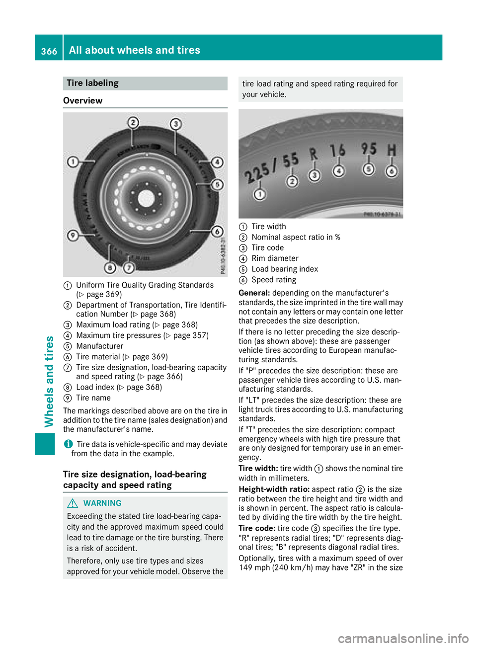
Overview
:Uniform Tire Quality Grading Standards
(Ypage 369)
;Department of Transportation, Tire Identifi-
cation Number (Ypage 368)
=Maximum load rating (Ypage 368)
?Maximum tire pressures (Ypage 357)
AManufacturer
BTire material (Ypage 369)
CTire size designation, load-bearing capacity
and speed rating (Ypage 366)
DLoad index (Ypage 368)
ETire name
The markings described above are on the tire in
addition to the tire name (sales designation) and
the manufacturer's name.
iTire data is vehicle-specific and may deviate
from the data in the example.
Tire size designation, load-bearing
capacity and speed rating
GWARNING
Exceeding the stated tire load-bearing capa-
city and the approved maximum speed could
lead to tire damage or the tire bursting. There is a risk of accident.
Therefore, only use tire types and sizes
approved for your vehicle model. Observe the
tire load rating and speed rating required for
your vehicle.
:Tire width
;Nominal aspect ratio in %
=Tire code
?Rim diameter
ALoad bearing index
BSpeed rating
General: depending on the manufacturer's
standards, the size imprinted in the tire wall may
not contain any letters or may contain one letter
that precedes the size description.
If there is no letter preceding the size descrip-
tion (as shown above): these are passenger
vehicle tires according to European manufac-
turing standards.
If "P" precedes the size description: these are
passenger vehicle tires according to U.S. man-
ufacturing standards.
If "LT" precedes the size description: these are
light truck tires according to U.S. manufacturing
standards.
If "T" precedes the size description: compact
emergency wheels with high tire pressure that
are only designed for temporary use in an emer-
gency.
Tire width: tire width:shows the nominal tire
width in millimeters.
Height-width ratio: aspect ratio;is the size
ratio between the tire height and tire width and
is shown in percent. The aspect ratio is calcula-
ted by dividing the tire width by the tire height.
Tire code: tire code=specifies the tire type.
"R" represents radial tires; "D" represents diag-
onal tires
; "B" represents diagonal radial tires.
Optionally, tires with a maximum speed of over
149 mph (240 km/h) may have "ZR" in the size
366All about wheels an d tires
Wheels and tires
Page 395 of 398

For more information about off-road fording, see
(Ypage 164).
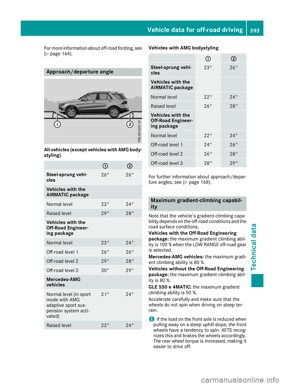
Approach/departure angle
All vehicles (except vehicles with AMG body-
styling)
:;
Steel-sprung vehi-
cles26°26°
Vehicles with the
AIRMATIC package
Normal level23°24°
Raised level29°28°
Vehicles with the
Off-Road Engineer-
ing package
Normal level23°24°
Off-road level 126°26°
Off-road level 229°28°
Off-road level 330°29°
Mercedes-AMG
vehicles
Normal level (in sport
mode with AMG
adaptive sport sus-
pension system acti-
vated)21°24°
Raised level23°24°
Vehicles with AMG bodystyling
:;
Steel-sprung vehi-
cles23°26°
Vehicles with the
AIRMATICpackage
Normal level22°24°
Raised level26°28°
Vehicles with the
Off-Road Engineer-
ing package
Normal level22°24°
Off-road level 124°26°
Off-road level 226°28°
Off-road level 328°29°
For further information about approach/depar-
ture angles, see (Ypage 168).
Maximum gradient-climbing capabil-
ity
Note that the vehicle's gradient-climbing capa-
bility depends on the off-road conditions and the
road surface conditions.
Vehicles with the Off-Road Engineering
package: the maximum gradient climbing abil-
ity is 100 % when the LOW RANGE off-road gear
is selected.
Mercedes-AMG vehicles: the maximum gradi-
ent climbing ability is 80 %.
Vehicles without the Off-Road Engineering
package: the maximum gradient climbing abil-
ity is 80 %.
GLE 550 e 4MATIC: the maximum gradient
climbing ability is 50 %.
Accelerate carefully and make sure that the
wheels do not spin when driving on steep ter-
rain.
iIf the load on the front axle is reduced when
pulling away on a steep uphill slope, the front
wheels have a tendency to spin. 4ETS recog-
nizes this and brakes the wheels accordingly. The rear wheel torque is increased, making it
easier to drive off.
Vehicle data for off-road driving393
Technical data
Z