2018 MERCEDES-BENZ GLE tire type
[x] Cancel search: tire typePage 348 of 398
driver's or front-passenger door, which could
damage the transmission.
! Do not tow with sling-type equipment. This
could damage the vehicle.
! Vehicles with differential locks: make sure
the differential locks are in automatic mode.
When towing, the differential locks must not
be switched on. The transmission may other-
wise be damaged.
! The vehicle can be towed a maximum of
30 miles (50km). The towing speed of 30 mph
(50 km/h) must not be exceeded.
If the vehicle has to be towed more than
30 miles (50km), the entire vehicle must be
raised and transported.
It is better to have the vehicle transported than
to have it towed away.
If the vehicle has suffered transmission damage,
have it transported on a transporter or trailer.
The automatic transmission must be in position
�\\ when the vehicle is being towed.
The battery must be connected and charged.
Otherwise, you: R
cannot turn the SmartKey to position �H in
the ignition lock R
cannot release the electric parking brake R
cannot shift the automatic transmission to
position �\\
Disarm the automatic locking feature before the
vehicle is towed ( Y
page 239). You could other-
wise be locked out when pushing or towing the
vehicle.
If the vehicle is in a dangerous area, it can be
towed out of that area with both axles on the
ground. In this case, the towing distance must
not be greater than 165 ft (50 m) and must not
exceed a towing speed of 6 mph (10 km/h). For
longer distances, have the vehicle loaded and
transported. Installing/removing the towing eye
Installing the towing eye
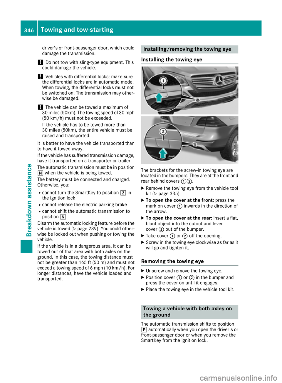
The brackets for the screw-in towing eye are
located in the bumpers. They are at the front and
rear behind covers �C�D .X
Remove the towing eye from the vehicle tool
kit ( Y
page 335). X
To open the cover at the front: press the
mark on cover �C inwards in the direction of
the arrow. X
To open the cover at the rear: insert a flat,
blunt object into the cutout and lever
cover �D out of the bumper. X
Take cover �C or �D off the opening.X
Screw in the towing eye clockwise as far as it
will go and tighten it.
Removing the towing eye X
Unscrew and remove the towing eye. X
Position cover �C or �D in the bumper and
press the cover on until it engages. X
Place the towing eye in the vehicle tool kit.
Towing a vehicle with both axles on
the ground
The automatic transmission shifts to position
�] automatically when you open the driver's or
front-passenger door or when you remove the
SmartKey from the ignition lock.346
Towing and tow-starting
Breakdown assistance
Page 355 of 398
MOExtended tires (tires with run-flat
properties) With MOExtended tires (tires with run flat char-
acteristics), you can continue to drive your vehi-
cle even if there is a total loss of pressure in one
or more tires.
MOExtended tires may only be used in conjunc-
tion with an active tire pressure loss warning
system or with an active tire pressure monitor
and on wheels specifically tested by Mercedes-
Benz.
Notes on driving with MOExtended tires with a
flat tire ( Y
page 336).
i Vehicles equipped with MOExtended tires
are not equipped with a TIREFIT kit at the fac-
tory. It is therefore recommended that you
additionally equip your vehicle with a TIREFIT
kit if you mount tires that do not feature run-
flat properties, e.g. winter tires. A TIREFIT kit
may be obtained from a qualified specialist
workshop.
Winter operation
General notes Have your vehicle winter-proofed at a qualified
specialist workshop at the onset of winter.
Observe the notes in the "Changing a wheel"
section ( Y
page 371).
Driving with summer tires At temperatures below 45 ‡ (+7 †), the elas-
ticity of summer tires and therefore also the
traction and braking capability are reduced con-
siderably. Change the tires on your vehicle to
M+S tires. Using summer tires at very cold tem-
peratures could cause cracks to form, thereby
damaging the tires permanently. Mercedes-
Benz cannot accept responsibility for this type
of damage.
G WARNING
Damaged tires can cause tire inflation pres-
sure loss. As a result, you could lose control of
your vehicle. There is a risk of accident.
Check the tires regularly for signs of damage
and replace any damaged tires immediately. M+S tires
G WARNING
M+S tires with a tire tread depth of less than
�
Page 363 of 398
Restarting the tire pressure monitor When you restart the tire pressure monitor, all
existing warning messages are deleted and the
warning lamps go out. The monitor uses the cur-
rently set tire pressures as the reference values
for monitoring. In most cases, the tire pressure
monitor will automatically detect the new refer-
ence values after you have changed the tire
pressure. However, you can also set reference
values manually as described here. The tire
pressure monitor then monitors the new tire
pressure values. X
Set the tire pressure to the value recommen-
ded for the corresponding driving situation on
the Tire and Loading Information placard on
the driver's side B-pillar ( Y
page 354).
You can find more tire pressure values for
various operating conditions in the tire pres-
sure table inside the fuel filler flap
( Y
page 355). X
Make sure that the tire pressure is correct on
all four wheels. X
Make sure that the SmartKey is in position �H
in the ignition lock. X
Press the �Y or �e button on the steering
wheel to select the Serv. menu.X
Press the �c or �d button to select
Tire Pressure .X
Press �v .
The multifunction display shows the current
tire pressure for the individual tires or the
Tire pressure will be displayed
after driving a few minutes message.X
Press the �d button.
The Use Current Pressures as New Ref‐
erence Values message appears in the mul-
tifunction display.
If you wish to confirm the restart: X
Press the �v button.
The Tire Press. Monitor Restarted mes-
sage appears in the multifunction display.
After driving for a few minutes, the system
checks whether the current tire pressures are
within the specified range. The new tire pres-
sures are then accepted as reference values
and monitored.
If you wish to cancel the restart: X
Press the �8 button.
The tire pressure values stored at the last
restart will continue to be monitored. Radio type approval for the tire pres-
sure monitor Country Radio type approval number
USA FCC ID: MRXMW2433A
FCC ID: MRXGG4
FCC ID: MRXMC34MA4
Canada IC: 2546A-MW2433A
IC: 2546A-GG4
IC: 2546A-MC34MA4
Loading the vehicle
Instruction labels for tires and loads
G WARNING
Overloaded tires can overheat, causing a
blowout. Overloaded tires can also impair the
steering and driving characteristics and lead
to brake failure. There is a risk of accident.
Observe the load rating of the tires. The load
rating must be at least half of the GAWR of
your vehicle. Never overload the tires by
exceeding the maximum load.
Two instruction labels on your vehicle show the
maximum possible load.
(1) The Tire and Loading Information placard is
on the B-pillar on the driver's side. The Tire
and Loading Information placard shows the
maximum permissible number of occu-
pants and the maximum permissible vehicle
load. It also contains details of the tire sizes
and corresponding pressures for tires
mounted at the factory.
(2) The vehicle identification plate is on the B-
pillar on the driver's side. The vehicle iden-
tification plate informs you of the gross
vehicle weight rating. It is made up of the
vehicle weight, all vehicle occupants, the
fuel and the cargo. You can also find infor-
mation about the maximum gross axle
weight rating on the front and rear axle.
The maximum gross axle weight rating is
the maximum weight that can be carried by
one axle (front or rear axle). Never exceed
the maximum load or the maxi mum g ross
a
xle weight rating for the front or rear axle.Loading the vehicle 361
Wheels and tires Z
Page 373 of 398
Sidewall The part of the tire between the tread and the
bead.
Weight of optional extras The combined weight of those optional extras
that weigh more than the replaced standard
parts and more than 2.3 kg (5 lbs). These
optional extras, such as high-performance
brakes, level control, a roof rack or a high-per-
formance battery, are not included in the curb
weight and the weight of the accessories.
TIN (Tire Identification Number) This is a unique identifier which can be used by
a tire manufacturer to identify tires, for example
for a product recall, and thus identify the pur-
chasers. The TIN is made up of the manufactur-
er's identity code, tire size, tire type code and
the manufacturing date.
Load bearing index The load bearing index (also load index) is a code
that contains the maximum load bearing capa-
city of a tire.
Traction Traction is the result of friction between the tires
and the road surface.
TWR (Tongue Weight Rating) The TWR specifies the maximum permissible
weight that the ball coupling of the trailer tow
hitch can support.
Treadwear indicators Narrow bars (tread wear bars) that are distrib-
uted over the tire tread. If the tire tread is level
with the bars, the wear limit of �
Page 378 of 398
the defective wheel has been replaced with a
new wheel.
Vehicles with a tire pressure control sys-
tem: all installed wheels must be equipped with
functioning sensors.
Wheel and tire combinations Information regarding permitted wheel/tire
combinations can be found at an authorized
Mercedes-Benz Center.
! For safety reasons, Mercedes-Benz recom-
mends that you only use tires and wheels
which have been approved by Mercedes-Benz
specifically for your vehicle.
These tires have been specially adapted for
use with the control systems, such as ABS or
ESP ®
, and are marked as follows: R
MO = Mercedes-Benz Original R
MOE = Mercedes-Benz Original Extended
(tires featuring run-flat characteristics) R
MO1 = Mercedes-Benz Original (only cer-
tain AMG tires)
Mercedes-Benz Original Extended tires may
only be used on wheels that have been spe-
cifically approved by Mercedes-Benz.
Only use tires, wheels or accessories tested
and approved by Mercedes-Benz. Certain
characteristics, e.g. handling, vehicle noise
emissions or fuel consumption, may other-
wise be adversely affected. In addition, when
driving with a load, tire dimension variations
could cause the tires to come into contact
with the bodywork and axle components. This
could result in damage to the tires or the vehi-
cle.
Mercedes-Benz accepts no liability for dam-
age resulting from the use o f tires, wheels or
a ccessories other than those tested and
approved.
Information on tires, wheels and approved
combinations can be obtained from any quali-
fied specialist workshop.
! Retreaded tires are neither tested nor rec-
ommended by Mercedes-Benz, since previ-
ous damage cannot always be detected on
retreaded tires. As a result, Mercedes-Benz
cannot guarantee vehicle safety if retreaded
tires are mounted. Do not mount used tires if you have no information about their previous
usage.
The recommended pressures for various oper-
ating conditions can be found: R
on the Tire and Loading Information placard
on the B-pillar on the driver's side R
in the tire pressure table in the fuel filler flap
Observe the notes on recommended tire pres-
sures under various operating conditions
( Y
page 354).
Check tire pressures regularly, and only when
the tires are cold. Comply with the maintenance
recommendations of the tire manufacturer in
the vehicle document wallet.
Notes on the vehicle equipment – always equip
the vehicle: R
with tires of the same size on a given axle (left
and right) R
with the same type of tires at a given time
(summer tires, w inter tires, MOExtended
ti res)
i Vehicles equipped with MOExtended tires
are not equipped with a TIREFIT kit at the fac-
tory. It is therefore recommended that you
additionally equip your vehicle with a TIREFIT
kit if you mount tires that do not feature run-
flat properties, e.g. winter tires. A TIREFIT kit
may be obtained from a qualified specialist
workshop.
Emergency spare wheel
Important safety notes
G WARNING
The wheel or tire size as well as the tire type of
the spare wheel or emergency spare wheel
and the wheel to be replaced may differ.
Mounting an emergency spare wheel may
severely impair the driving characteristics.
There is a risk of an accident.
To avoid hazardous situations: R
adapt your driving style accordingly and
drive carefully. R
never mount more than one spare wheel or
emergency spare wheel that differs in size.376
Emergency spare whee l
Wheels an d tires
Page 379 of 398
R
only use a spare wheel or emergency spare
wheel of a different size briefly. R
do not switch ESP ®
off.R
have a spare wheel or emergency spare
wheel of a different size replaced at the
nearest qualified specialist workshop.
Observe that the wheel and tire dimensions
as well as the tire type must be correct.
! Mercedes-AMG vehicles with
"Minispare" emergency spare wheel: only
use the "Minispare" emergency spare wheel
on the rear axle . If you mount the
"Minispare" emergency spare wheel on the
front axle, this could result in damage to the
brake system.
If a tire on the front axle is defective, an intact
wheel from the rear axle must first be
replaced with the "Minispare" emergency
spare wheel. The damaged wheel on the front
axle can then be replaced by the undamaged
wheel from the rear axle.
Make sure to note the placard on the
"Minispare" emergency spare wheel.
When using an emergency spare wheel or spare
wheel of a different size, you must not exceed
the maximum speed of 50 mph (80 km/ h) .
You should regularly check the pressure of the
emergency spare wheel, particularly prior to
long trips, and correct the pressure as neces-
sary ( Y
page 354). The value on the wheel is
valid.
Snow chains must not be mounted on emer-
gency spare wheels.
General notes Information regarding permitted emergency
spare wheels can be found at an authorized
Mercedes-Benz Center.
Mounting the emergency spare wheel is descri-
bed under "Mounting a wheel" ( Y
page 372).
An emergency spare wheel may also be moun-
ted against the direction of rotation. Observe
the time restriction on use as well as the speed
limitation specified on the emergency spare
wheel.
Replace the tires after six years at the latest,
regardless of wear. This also applies to the
emergency spare wheel. When you are driving with the collapsible spare
wheel mounted, the tire pressure loss warning
system or the tire pressure monitor cannot func-
tion reliably. Only restart the tire pressure loss
warning system or tire pressure monitor when
the defective wheel has been replaced with a
new wheel.
Vehicles with tire pressure monitor: after
mounting an emergency spare wheel, the sys-
tem may still display the tire pressure of the
removed wheel for a few minutes. The value dis-
played for the mounted emergency spare wheel
is not the same as the current tire pressure of
the emergency spare wheel.
Removing/stowing the emergency
spare wheel
Vehicles with a "Minispare" emergency
spare wheel under the cargo compart-
ment floor Always observe the instructions and safety
notes in the "Mounting a wheel" section
( Y
page 372).
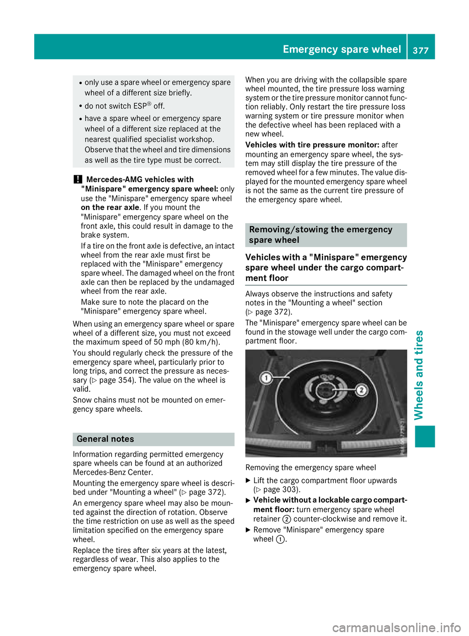
The "Minispare" emergency spare wheel can be
found in the stowage well under the cargo com-
partment floor.
Removing the emergency spare wheel X
Lift the cargo compartment floor upwards
( Y
page 303). X
Vehicle without a lockable cargo compart-
ment floor: turn emergency spare wheel
retainer �D counter-clockwise and remove it. X
Remove "Minispare" emergency spare
wheel �C .Emergency spare wheel 377
Wheels and tires Z