2018 MERCEDES-BENZ G-CLASS clock
[x] Cancel search: clockPage 9 of 294

Problem with the rear window
defroster ........................................101
Problems with "cooling with air
dehumidification" .............................9 8
Refrigerant .................................... .287
Refrigerant filling capacity ............. 288
Setting the air distribution ...............9 9
Setting the air vents ...................... 102
Setting the airflow ........................... 99
Setting the temperature .................. 99
Switching air-recirculation mode
on/off ............................................ 102
Switching on/off .............................. 98
Switching residual heat on/off ...... 102
Switching the rear window
defroster on/off ............................ 101
Switching the ZONE function
on/off ............................................ 100
Windshield defroster ...................... 101
Clock (on-board computer) ............... 169
Cockpit
Overview .......................................... 31
COMAND
see separate operating instructions
COMAND display
Cleaning ......................................... 241
Combination switch ............................ 88
Connecting a USB device
see also Digital Operator's Man-
ual .................................................. 203
Consumption statistics (on-board
computer) .......................................... 163
Controller ........................................... 204
Controlling speed
see DISTRONIC PLUS
Convenience closing feature .............. 70
Convenience opening feature ............ 70
Coolant (engine)
Checking the level ......................... 234
Display message ............................ 180
Filling capacity ............................... 287
Notes ............................................. 286
Temperature (on-board com-
puter) ............................................. 171
Temperature gauge ........................ 161
Warning lamp ................................. 199 Cooling
see Climate control
Copyright ............................................. 29
Cruise control
Cruise control lever ....................... 133
Deactivating ................................... 134
Driving system ............................... 133
Functio
n/notes ............................. 133
General notes ................................ 133
Important safety notes .................. 133
Resuming the stored speed ........... 134
Setting a speed .............................. 134
Storing and maintaining current
speed ............................................. 133
Cup holder
Center console .............................. 215
Important safety notes .................. 215
Rear compartment ......................... 215
D
Datasee Technical data
Date (on-board computer) ................ 168
Daytime running lamps
Display message ............................ 180
Switching on/off (on-board com-
puter) ............................................. 169
Switching on/off (switch) ................ 86
Delayed switch-off
Exterior lighting (on-board com-
puter) ............................................. 169
Interior lighting .............................. 169
Diagnostics connection ...................... 27
Differential locks
Disengaging ................................... 153
Engaging ........................................ 151
Front axle ...................................... 152
General notes ................................ 151
Rear axle ........................................ 152
Terrain ........................................... 151
Transfer case ................................. 152
Digital Operator's Manual
Help ................................................. 22
Introduction ..................................... 22
Digital speedometer ......................... 163
Display messages
Calling up (on-board computer) ..... 174
Index7
Page 70 of 294
XTo deactivate:press and hold button :for
approximately five seconds until a tone
sounds.
XTo activate: press and hold button ;for
approximately five seconds until a tone
sounds.
If you press one of the two buttons and do not
hear a tone, the relevant setting has already
been selected.
The vehicle is locked automatically when the
ignition is switched on and the wheels are turn-
ing.
You could therefore be locked out if:
Rthe vehicle is being pushed.
Rthe vehicle is being towed.
Rthe vehicle is being tested on a dynamometer.
You can also switch the automatic locking func-
tion on and off using the on-board computer
(
Ypage 170).
Locking/unlocking the driver's door
with the mechanical key
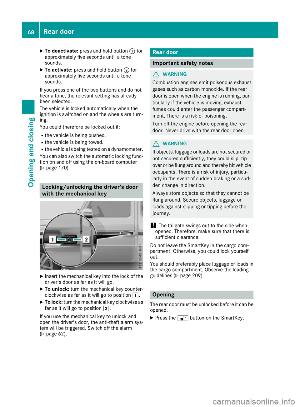
XInsert the mechanical key into the lock of the driver's door as far as it will go.
XTo unlock: turn the mechanical key counter-
clockwise as far as it will go to position 1.
XTo lock:turn the mechanical key clockwise as
far as it will go to position 2.
If you use the mechanical key to unlock and
open the driver's door, the anti-theft alarm sys-
tem will be triggered. Switch off the alarm
(
Ypage 62).
Rear door
Important safety notes
GWARNING
Combustion engines emit poisonous exhaust
gases such as carbon monoxide. If the rear
door is open when the engine is running, par-
ticularly if the vehicle is moving, exhaust
fumes could enter the passenger compart-
ment. There is a risk of poisoning.
Turn off the engine before opening the rear
door. Never drive with the rear door open.
GWARNING
If objects, luggage or loads are not secured or
not secured sufficiently, they could slip, tip
over or be flung around and thereby hit vehicle
occupants. There is a risk of injury, particu-
larly in the event of sudden braking or a sud-
den change in direction.
Always store objects so that they cannot be
flung around. Secure objects, luggage or
loads against slipping or tipping before the
journey.
!The tailgate swings out to the side when
opened. Therefore, make sure that there is
sufficient clearance.
Do not leave the SmartKey in the cargo com-
partment. Otherwise, you could lock yourself
out.
You should preferably place luggage or loads in
the cargo compartment. Observe the loading
guidelines (
Ypage 209).
Opening
The rear door must be unlocked before it can be opened.
XPress the %button on the SmartKey.
68Rear door
Opening and closing
Page 74 of 294
Opening and closing the sliding sun-
roof
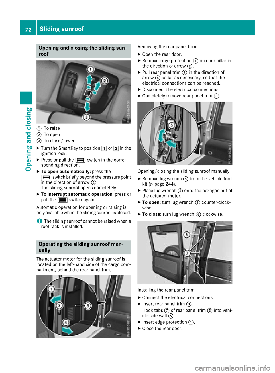
:To raise
;To open
=To close/lower
XTurn the SmartKey to position1or2 in the
ignition lock.
XPress or pull the ¡switch in the corre-
sponding direction.
XTo open automatically: press the
¡ switch briefly beyond the pressure point
in the direction of arrow ;.
The sliding sunroof opens completely.
XTo interrupt automatic operation: press or
pull the ¡switch again.
Automatic operation for opening or raising is
only available when the sliding sunroof is closed.
iThe sliding sunroof cannot be raised when a
roof rack is installed.
Operating the sliding sunroof man-
ually
The actuator motor for the sliding sunroof is
located on the left-hand side of the cargo com-
partment, behind the rear panel trim.
Removing the rear panel trim
XOpen the rear door.
XRemove edge protection :on door pillar in
the direction of arrow ;.
XPull rear panel trim=in the direction of
arrow ?as far as necessary, so that the
electrical connections can be reached.
XDisconnect the electrical connections.
XCompletely remove rear panel trim =.
Opening/closing the sliding sunroof manually
XRemove lug wrenchAfrom the vehicle tool
kit (Ypage 244).
XPlace lug wrench Aonto the hexagon nut of
the actuator motor.
XTo open: turn lug wrench Acounter-clock-
wise.
XTo close: turn lug wrench Aclockwise.
Installing the rear panel trim
XConnect the electrical connections.
XInsert rear panel trim =.
Hook tabs Cof rear panel trim =into vehi-
cle side wall B.
XInsert edge protection :.
XClose the rear door.
72Sliding sunroof
Opening and closing
Page 93 of 294
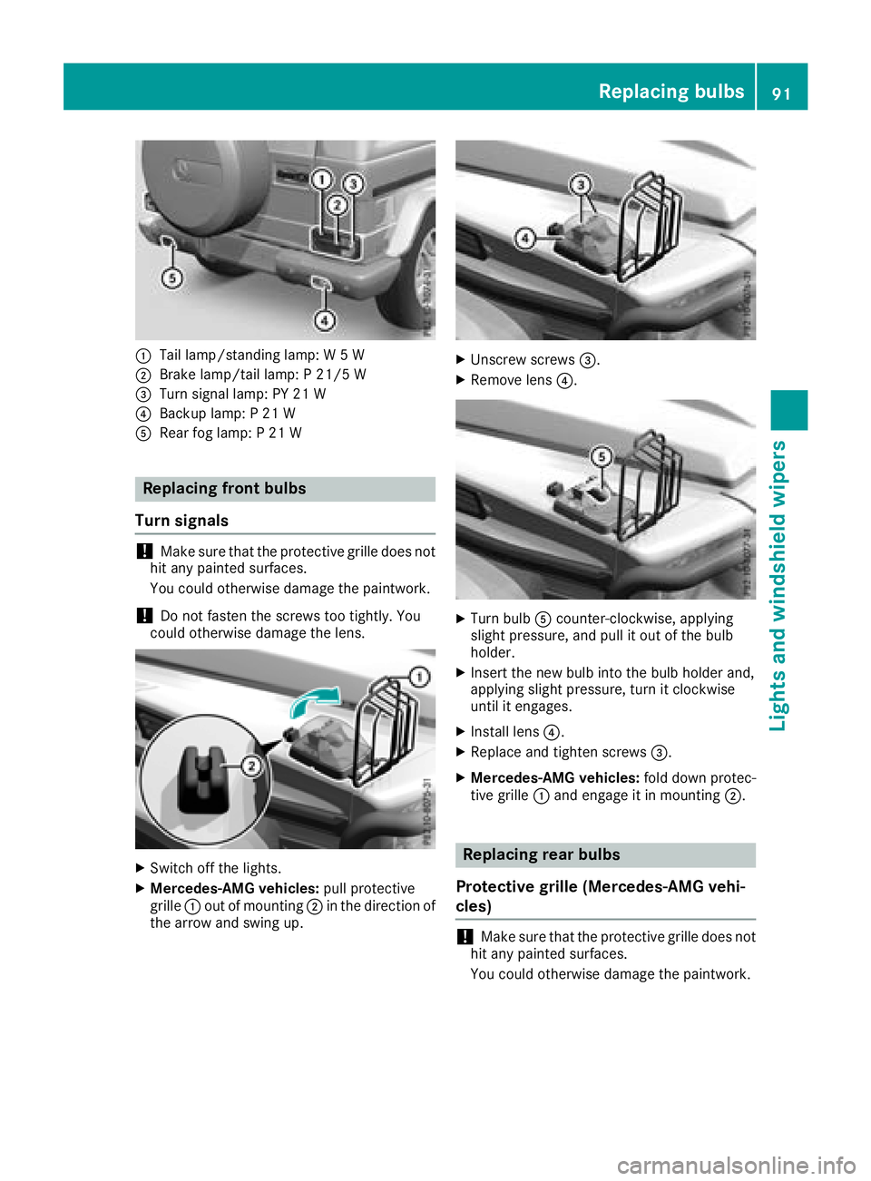
:Tail lamp/standing lamp: W 5 W
;Brake lamp/tail lamp: P 21/5 W
=Turn signal lamp: PY 21 W
?Backup lamp: P 21 W
ARear fog lamp: P 21 W
Replacing front bulbs
Turn signals
!Make sure that the protective grille does not
hit any painted surfaces.
You could otherwise damage the paintwork.
!Do not fasten the screws too tightly. You
could otherwise damage the lens.
XSwitch off the lights.
XMercedes-AMG vehicles: pull protective
grille :out of mounting ;in the direction of
the arrow and swing up.
XUnscrew screws =.
XRemove lens?.
XTurn bulbAcounter-clockwise, applying
slight pressure, and pull it out of the bulb
holder.
XInsert the new bulb into the bulb holder and,
applying slight pressure, turn it clockwise
until it engages.
XInstall lens ?.
XReplace and tighten screws =.
XMercedes-AMG vehicles:fold down protec-
tive grille :and engage it in mounting ;.
Replacing rear bulbs
Protective grille (Mercedes-AMG vehi-
cles)
!Make sure that the protective grille does not
hit any painted surfaces.
You could otherwise damage the paintwork.
Replacing bulbs91
Lights and windshield wipers
Z
Page 94 of 294
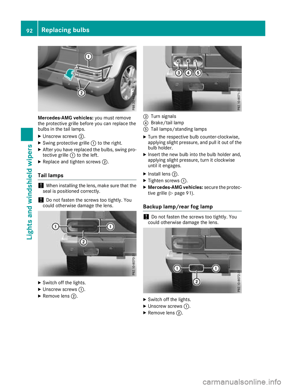
Mercedes-AMG vehicles:you must remove
the protective grille before you can replace the
bulbs in the tail lamps.
XUnscrew screws ;.
XSwing protective grille :to the right.
XAfter you have replaced the bulbs, swing pro-
tective grille :to the left.
XReplace and tighten screws ;.
Tail lamps
!When installing the lens, make sure that the
seal is positioned correctly.
!Do not fasten the screws too tightly. You
could otherwise damage the lens.
XSwitch off the lights.
XUnscrew screws :.
XRemove lens;.
=Turn signals
?Brake/tail lamp
ATail lamps/standing lamps
XTurn the respective bulb counter-clockwise,
applying slight pressure, and pull it out of the
bulb holder.
XInsert the new bulb into the bulb holder and,
applying slight pressure, turn it clockwise
until it engages.
XInstall lens;.
XTighten screws :.
XMercedes-AMG vehicles: secure the protec-
tive grille (Ypage 91).
Backup lamp/rear fog lamp
!Do not fasten the screws too tightly. You
could otherwise damage the lens.
XSwitch off the lights.
XUnscrew screws :.
XRemove lens;.
92Replacing bulbs
Lights and windshield wipers
Page 95 of 294
XTurn bulb=counter-clockwise, applying
slight pressure, and pull it out of the bulb
holder.
XInsert the new bulb into the bulb holder and,
applying slight pressure, turn it clockwise
until it engages.
XInstall lens ;.
XTighten screws :.
Windshield wipers
Switching the windshield wipers
on/off
!
Do not operate the windshield wipers when
the windshield is dry, as this could damage
the wiper blades. Moreover, dust that has col-
lected on the windshield/rear window can
scratch the glass if wiping takes place when
the windshield/rear window is dry.
If it is necessary to switch on the windshield
wipers in dry weather conditions, always use
washer fluid when operating the windshield
wipers.
!If the windshield wipers leave smears on the
windshield/rear window after the vehicle has
been washed in an automatic car wash, this
may be due to wax or other residue. Clean the
windshield/rear window with washer fluid
after an automatic car wash.
!Intermittent wiping with rain sensor: due to
optical influences and the windshield becom-
ing dirty in dry weather conditions, the wind-
shield wipers may be activated inadvertently.
This could then damage the windshield wiper
blades or scratch the windshield.
For this reason, you should always switch off
the windshield wipers in dry weather.
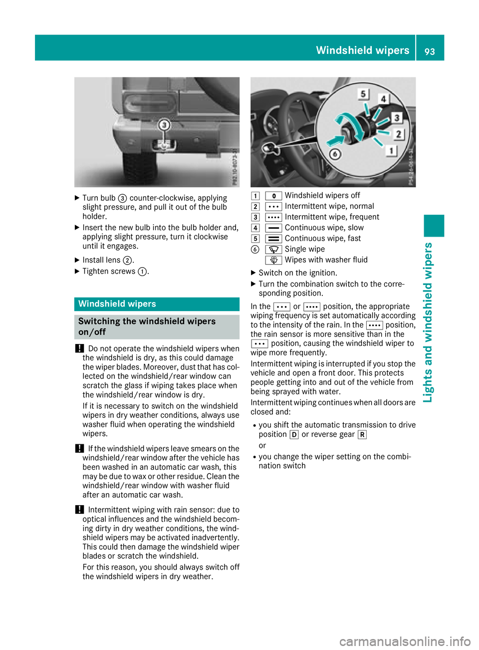
1$ Windshield wipers off
2ÄIntermittent wipe, normal
3ÅIntermittent wipe, frequent
4°Continuous wipe, slow
5¯Continuous wipe, fast
BíSingle wipe
î Wipes with washer fluid
XSwitch on the ignition.
XTurn the combination switch to the corre-
sponding position.
In the ÄorÅ position, the appropriate
wiping frequency is set automatically according
to the intensity of the rain. In the Åposition,
the rain sensor is more sensitive than in the
Ä position, causing the windshield wiper to
wipe more frequently.
Intermittent wiping is interrupted if you stop the vehicle and open a front door. This protects
people getting into and out of the vehicle from
being sprayed with water.
Intermittent wiping continues when all doors are
closed and:
Ryou shift the automatic transmission to drive
position hor reverse gear k
or
Ryou change the wiper setting on the combi-
nation switch
Windshield wipers93
Lights and windshield wipers
Z
Page 123 of 294
=Instruction label for fuel type to be refueled
?To insert the fuel filler cap
XSwitch off the engine.
XRemove the SmartKey from the ignition lock.
XPress the fuel filler flap in the direction of
arrow:.
The fuel filler flap swings up.
XTurn the fuel filler cap counterclockwise and
remove it.
XInsert the fuel filler cap into the holder
bracket on the inside of filler flap ?.
XCompletely insert the filler neck of the fuel
pump nozzle into the tank and refuel.
XOnly fill the tank until the pump nozzle
switches off.
Do not add any more fuel after the pump stops
filling for the first time. Otherwise, fuel may leak
out.
Closing the fuel filler flap
XReplace the cap on the filler neck and turn
clockwise until it engages audibly.
XClose the fuel filler flap.
Close the fuel filler flap before locking the vehi-
cle.
If you are driving with the fuel filler cap open, the
8 reserve fuel warning lamp flashes. A mes-
sage appears in the multifunction display
(
Ypage 183).
Fuel filler flap emergency release
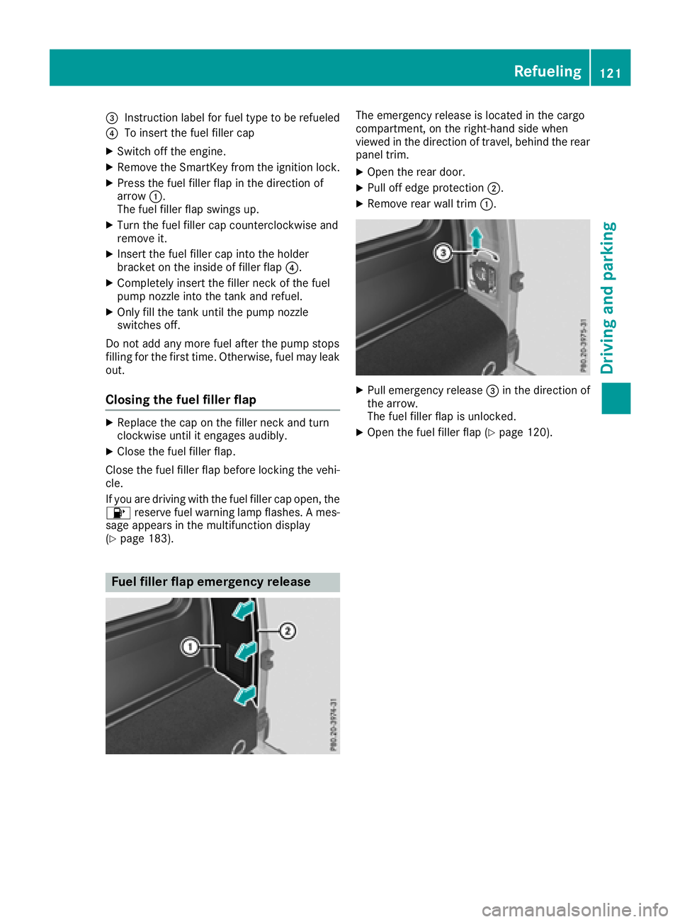
The emergency release is located in the cargo
compartment, on the right-hand side when
viewed in the direction of travel, behind the rear
panel trim.
XOpen the rear door.
XPull off edge protection ;.
XRemove rear wall trim:.
XPull emergency release =in the direction of
the arrow.
The fuel filler flap is unlocked.
XOpen the fuel filler flap (Ypage 120).
Refueling121
Driving and parking
Z
Page 161 of 294
Permissible trailer and drawbar loads
Weight specifications
The gross trailer weight is calculated as the
weight of the trailer plus the weight of the load
and the trailer's equipment.
You will find permissible trailer loads under
"Technical data" (
Ypage 291).
Loading a trailer
RWhen loading the trailer, make sure that nei-
ther the permissible gross trailer weight nor
the permissible gross vehicle weight are
exceeded. The permissible gross vehicle
weight is indicated on the identification plate on the B-pillar on the driver's side of the vehi-
cle.
You can find the maximum permissible values
on the type plates of your vehicle and the
trailer. When calculating how much weight
the vehicle and trailer may carry, pay atten-
tion to the respective lowest values.
RThe trailer drawbar load on the ball coupling
must be added to the rear axle load to avoid
exceeding the permissible gross axle weight.
The permissible gross vehicle weight is indi-
cated on the identification plate on the B-pil-
lar on the driver's side of the vehicle.
Mercedes-Benz recommends a trailer load
where the trailer drawbar noseweight accounts
for 8% to 15% of the permissible gross trailer
weight.
Additional accessories, passengers and load
reduce the permissible trailer load and nose-
weight that your vehicle can tow.
Checking the vehicle and trailer weight
RHave the towing vehicle, including the driver,
passengers and load, and completely loaded
trailer weighed on a suitable weighing
machine. This will allow you to ensure that the
weights of the towing vehicle and trailer com-
ply with the maximum permissible values.
RCheck the gross axle weight rating of the front
and rear axles, the gross weight of the trailer
and trailer drawbar load.
Trailer power supply
!
You can connect accessories with a maxi-
mum power consumption of 180 W to the
permanent power supply.
You must not charge a trailer battery using the
power supply.
The trailer socket of your vehicle is equipped at
the factory with a permanent power supply.
The permanent power supply is supplied via
trailer socket pin 9.
A qualified specialist workshop can provide
more information about installing the trailer
electrics.
Trailer with 7-pin connector
General notes
Trailers with 7-pin connector: you can make a
connection to the 13-pin connector on the ball
coupling using an adapter plug or, if necessary,
an adapter cable. Both can be obtained in a
qualified specialist workshop.
Installing the adapter
!Make sure that there is enough slack in the
cable for cornering so that the cable cannot
become detached.
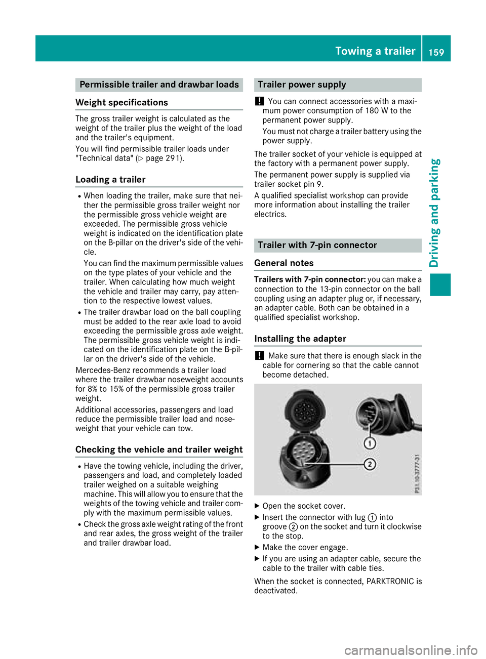
XOpen the socket cover.
XInsert the connector with lug :into
groove ;on the socket and turn it clockwise
to the stop.
XMake the cover engage.
XIf you are using an adapter cable, secure the
cable to the trailer with cable ties.
When the socket is connected, PARKTRONIC is
deactivated.
Towing a trailer159
Driving and parking
Z