Page 109 of 593

#
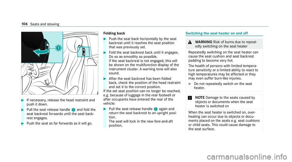
If necessar y,release the head restra int and
push it down. #
Pull the seat release handle 1and fold the
seat backrest forw ards until the seat back‐
re st engages. #
Push the seat as farfo rw ards as it will go. Fo
lding back #
Push the seat back horizon tally by the seat
backrest until it reaches the seat position
th at wa s pr eviously set. #
Foldthe seat backrest back until it engages.
Do so as smoo thly as possible.
If th e seat backrest is not engaged, this will
be shown on the multifunction display of the
instrument clus ter.A wa rning tone will also
sound. #
Afterth e seat backrest has been folded
bac k,check the position of the head restra int
and set it tothe cor rect position.
If th e set seat position can no longer be reached,
e.g. because of luggage in there ar foot we ll or
af te r occupants ha veentered there ar of the
ve hicle: #
Pull the seat release handle 1again and
re turn the seat backrest toan upright posi‐
tion.
The seat will lock in the new fore -and-aft
position. Switching the seat hea
ter on and off &
WARNING Risk of bu rns due torepeat‐
edly switching on the seat heater
Re peatedly switching on the seat heater can
cause the seat cushion and seat backrest
padding tobecome very hot.
The health of persons with limited temp era‐
ture sensitivity or a limited ability toreact to
high temp eratures may be af fected or they
may even su ffer burn-like injuries. #
Do not repeatedly switch on the seat
heater. *
NO
TEDama getothe seats caused by
objects or documents when the seat
heater is switched on When
the seat heater is switched on, over‐
heating can occur due toobjects or docu‐
ments placed on the seats e.g. seat cushions
or child seats. This could cause damage to
th e seat sur face. 106
Seats and stowing
Page 116 of 593

ke
y if the "Digital Vehicle Key" function
is activated via Mercedes me connect. The memory function can be used when
the igni‐
tion is switched off.
St oring
Seat adjustments for up tothre e people can be
st ored and called up using the memory function.
The following sy stems can be selected:
R Seat, backrest and head restra int
R Steering wheel
R Outside mir rors
R Head-up display #
Set the seat, thesteering wheel, the head-up
display and the outside mir rors to the
desired position. #
Press memory button M toge ther with one of
preset position buttons 1,2 or 3.
An acou stic signal sounds. The settings are
st ored. #
Tocall up: press or brief lyhold preset posi‐
tion button 1,2 or 3.
The front seat, thesteering column, the
head-up display and the outside mir ror mo ve
to thestored position. St
ow age areas Note
s on loading theve hicle &
DANG ER Risk of exhaust gas poisoning
Combustion engines emit poisonous exhaust
ga ses such as carbon monoxide. Exhaust
ga ses can enter theve hicle interior if the
boot lid is open when the engine is running,
especially if theve hicle is in motion. #
Alw ays switch off the engine before
opening the boot lid. #
Never drive with the boot lid open. Seats and
stowing 11 3
Page 120 of 593

Fo
lding there ar seat backrest back
* NO
TEDama getothe seat belt The seat belt could become trapped and
thus
damaged when folding back the seat back‐
re st. #
Make sure that the seat belt is not trap‐
ped when folding back the seat back‐
re st. #
Movethe driver's or front passenger seat for‐
wa rds, if necessar y. #
Fold cor responding seat backrest 1back
until it engages.
Left and right seat backrests: ifth e seat
backrest is not engaged and loc ked, this will
be shown on the multifunction display on the
instrument clus ter.
Centre seat backres t:ifth e seat backrest is
not engaged and loc ked, red lock verification
indicator 2will be visible. Lo
cking there lease catch of the centre rear
seat backrest
Re quirements:
R The left and centre seat backrests are
engaged and joined toge ther.
Yo u can lock the cent reseat backrest release
cat chifyo uwa nttosecure the boot against
unauthorised access. The cent reseat backrest
can then be folded forw ards on lytoge ther with
th e left seat backrest. Seats and
stowing 117
Page 129 of 593

R
The mobile phone may heat up during the
ch arging process. The mobile phone can be
cooled in the mobile phone stowage com‐
partment when the air conditioning sy stem is
switched on. The cooling output in the
mobile phone stowage compartment is high‐
est when the controller in theglove box is
closed.
R Toensure more ef ficient charging and con‐
nection with theve hicle's exterior aerial,
re mo vethe pr otective co ver from the mobile
phone.
R When charging, the mat should be used if
possible. Wire
lesscharging of the mobile phone Requ
irements:
R The mobile phone is suitable for wireless
ch arging (Qi-compatible mobile phone). Yo u
can find a li stof Qi-compatible mobile
phones at:
http://www.mercedes-benz.com/connect #
Place the mobile phone as close tothe
centre of mat 1as possible wi th the display
fa cing up wards.
When thech arging symbol is shown in the
multimedia sy stem, the mobile phone is
being charge d.
Malfunctions during thech arging process are
shown in the multimedia sy stem displa y.
% The mat can be remo vedfo r cleaning, e.g.
using clean, luk ewarmwate r. Fi
tting and removing the floormats &
WARNING Risk of accident due to
objects in the driver's foot we ll
Objects in the driver's foot we ll may impede
pedal tr avel or block a depressed pedal.
This jeopardises the operating and road
saf ety of theve hicle. #
Stow all objects in theve hicle securely
so that they cannot getinto the driver's
fo ot we ll. #
Alw aysfit th efloor mats securely and
as prescribed in order toensure that
th ere is alw ays suf ficient room forthe
pedals. #
Do not use loose floor mats and do not
place floor mats on top of one ano ther. 12 6
Seats and stowing
Page 137 of 593

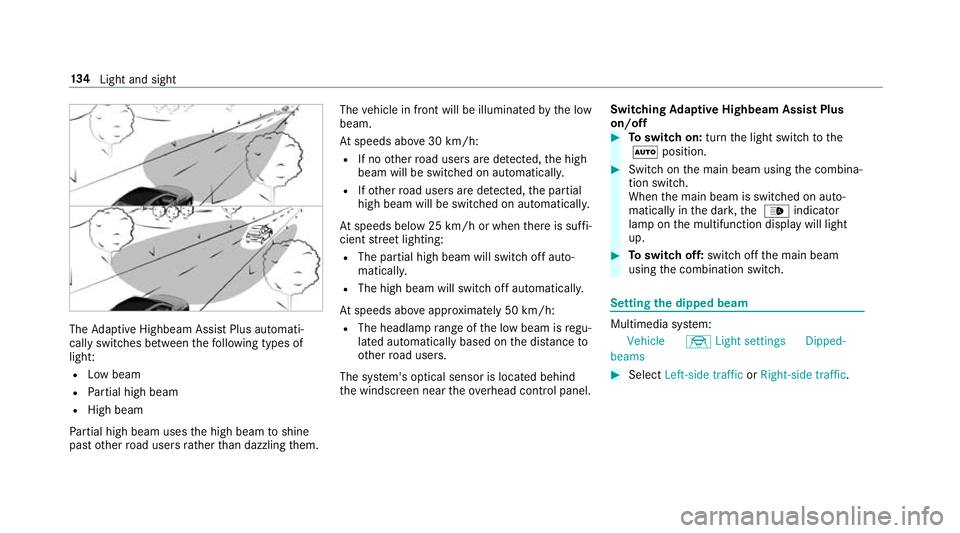
The
Adaptive Highbeam Assist Plus automati‐
cally swit ches between thefo llowing types of
light:
R Low beam
R Partial high beam
R High beam
Pa rtial high beam uses the high beam toshine
past other road users rath er than dazzling them. The
vehicle in front will be illuminated bythe low
beam.
At speeds abo ve30 km/h:
R If no other road users are de tected, the high
beam will be switched on automaticall y.
R Ifot her road users are de tected, the partial
high beam will be switched on automaticall y.
At speeds below 25 km/h or when there is suf fi‐
cient stre et lighting:
R The partial high beam will switch off auto‐
maticall y.
R The high beam will switch off automaticall y.
At speeds abo veappr oximately 50 km/h:
R The headlamp range of the low beam is regu‐
lated automatically based on the dis tance to
ot her road users.
The sy stem's optical sensor is located behind
th e windscreen near theove rhead control panel. Switching
Adaptive Highbeam Assist Plus
on/off #
Toswitch on: turnthe light switch tothe
à position. #
Switch on the main beam using the combina‐
tion switch.
When the main beam is switched on auto‐
matically in the dar k,the _ indicator
lamp on the multifunction display will light
up. #
Toswitch off: switch offthe main beam
using the combination switch. Setting
the dipped beam Multimedia sy
stem:
Vehicle ÷Light settings Dipped-
beams #
Select Left-side traffic orRight-side traffic. 134
Light and sight
Page 138 of 593

Setting
theex terior lighting switch-off delay
time Multimedia sy
stem:
Vehicle ÷Light settings Exterior
light shut-off #
Set the switch-off delay time. Setting
the sur round lighting Multimedia sy
stem:
Vehicle ÷Light settings Locator
lighting #
Activate Oor deacti vate ª the function.
If th e sur round lighting is swit ched on, theex te‐
ri or lighting remains lit for 40 seconds af terthe
ve hicle is unloc ked. When youstart theve hicle,
th e sur round lighting is deactivated and the
automatic driving lights are activated. Interior lighting
Ad
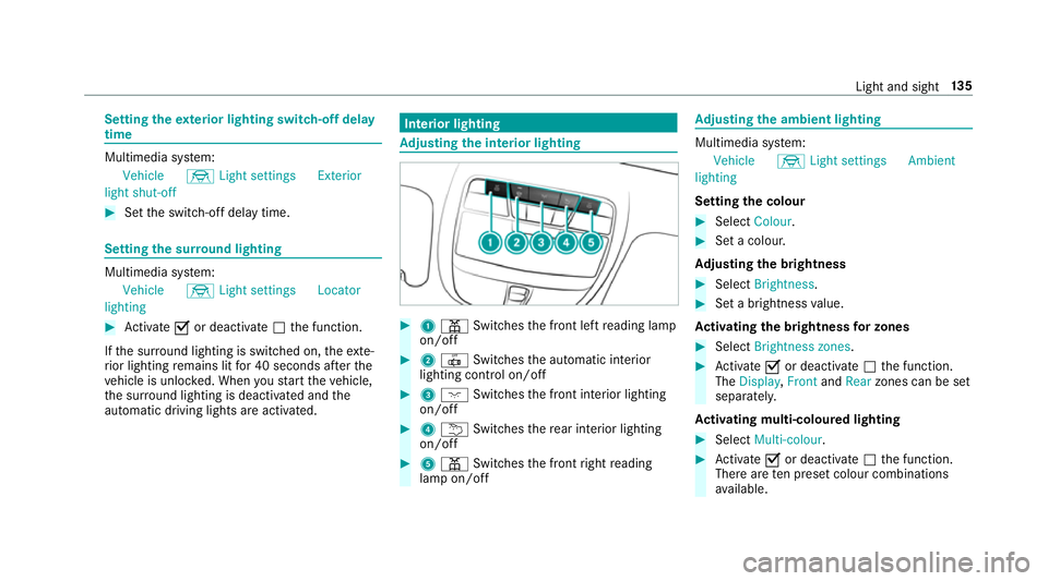
justing the in terior lighting #
1 p Switches the front left reading lamp
on/off #
2 | Switches the automatic interior
lighting control on/off #
3 c Switches the front interior lighting
on/off #
4 u Switches there ar interior lighting
on/off #
5 p Switches the front right reading
lamp on/off Ad
justing the ambient lighting Multimedia sy
stem:
Vehicle ÷Light settings Ambient
lighting
Setting the colour #
Select Colour. #
Set a colour.
Ad justing the brightness #
Select Brightness . #
Set a brightness value.
Ac tivating the brightness for zones #
Select Brightness zones . #
Activate Oor deacti vate ª the function.
The Display ,Front andRear zones can be set
separately.
Ac tivating multi-coloured lighting #
Select Multi-colour. #
Activate Oor deacti vate ª the function.
There are ten preset colour combinations
av ailable. Light and sight
13 5
Page 141 of 593

Fi
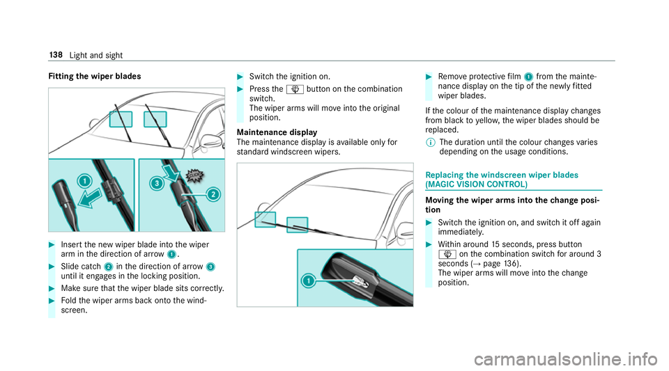
tting the wiper blades #
Inse rtthe new wiper blade into the wiper
arm in the direction of ar row1. #
Slide catch 2inthe direction of ar row 3
until it engages in the locking position. #
Make sure that the wiper blade sits cor rectly. #
Foldthe wiper arms back onto the wind‐
screen. #
Switch the ignition on. #
Press theî button on the combination
switch.
The wiper arms will mo veinto the original
position.
Maintenance display
The maintenance display is available on lyfor
st andard windsc reen wipers. #
Remo veprotective film 1 from the mainte‐
nance display on the tip of the newly fitted
wiper blades.
If th e colour of the maintenance display changes
from black to yellow, the wiper blades should be
re placed.
% The duration until the colour changes varies
depending on the usage conditions. Re
placing the windsc reen wiper blades
(MAGIC VISION CONT ROL) Moving
the wiper arms into thech ange posi‐
tion #
Switch the ignition on, and switch it off again
immediatel y. #
Within around 15seconds, press button
î onthe combination switch for around 3
seconds (→ page136).
The wiper arms will mo veinto thech ange
position. 13 8
Light and sight
Page 149 of 593

1
w Setsthete mp erature, left
2 _ Setsthe air distribution, left
3 H Setsthe air flow or switches off climate
control
4 Ã Sets climate control toautomatic
mode (→ page147)
5 ¬ Defrosts the windscreen
6 ! Calls up the air conditioning menu Switches
residual heat on/off (→ page148)
7 ¤ Switches there ar wind owheater
on/off
8 Vehicles without a stationary heater:
¿ switches the A/C function on/off
(→ page 147)
Ve hicles with a stationary heater: &
swit ches thest ationary heater on/off
(→ page 150)
9 g Switches ai r-re circulation mode on/off
(→ page 148)
A _ Setsthe air distribution, right
B w Setsthete mp erature, right
Re ar operating unit
Yo u can set thete mp erature forth e entire rear
compartment using buttons 1or3. 1
Sets thete mp erature
2 Display
3 Sets thete mp erature Operating
the clima tecont rol sy stem Switching clima
tecont rol on/off #
Toswitch on: setthe air flow toleve l 1 or
higher using theH button. #
Toswitch off: setthe air flow toleve l 0 using
th eH button. 14 6
Climate cont rol