2018 MERCEDES-BENZ CLS radio
[x] Cancel search: radioPage 167 of 334

This indicates that you have now reached the
minimum distance.
Deactivating/activating PARKTRONIC
�C
Indicator lamp�D
Deactivates/activates PARKTRONIC If indicator lamp �D lights up, PARKTRONIC is
deactivated. Active Parking Assist is then also
deactivated.
i PARKTRONIC is automatically activated
when you turn the SmartKey to position 2 in
the ignition lock.
Problems with PARKTRONIC Problem
Possible causes/consequences and �P Solutions
Only the red segments in
the PARKTRONIC warn-
ing displays are lit. You
also hear a warning tone
for approximately two
seconds.
PARKTRONIC is then
deactivated and the indi-
cator lamp on the
PARKTRONIC button
lights up. PARKTRONIC has malfunctioned and has switched off. X
If problems persist, have PARKTRONIC checked at a qualified spe-
cialist workshop.
Only the red segments in
the PARKTRONIC warn-
ing displays are lit.
PARKTRONIC is then
deactivated. The PARKTRONIC sensors are dirty or there is interference. X
Clean the PARKTRONIC sensors ( Y
page 274).X
Switch the ignition back on.
The problem may be caused by an external source of radio or ultra-
sound waves. X
See if PARKTRONIC functions in a different location.
Active Parking Assist
General notes
Active Parking Assist is an electronic parking aid
with ultrasound. It measures the road on both
sides of the vehicle. A parking symbol indicates
a suitable parking space. Active steering inter-
vention and brake application can assist you during parking. You may also use PARKTRONIC
( Y
page 163).
Important safety notes
Active Parking Assist is merely an aid. It is not a
replacement for your attention to your immedi-
ate surroundings. You are always responsibleDriving systems 165
Driving and parking Z
Page 195 of 334
able to complete the next two changes of direc-
tion without changing lane.
Other status indicators of the naviga-
tion system
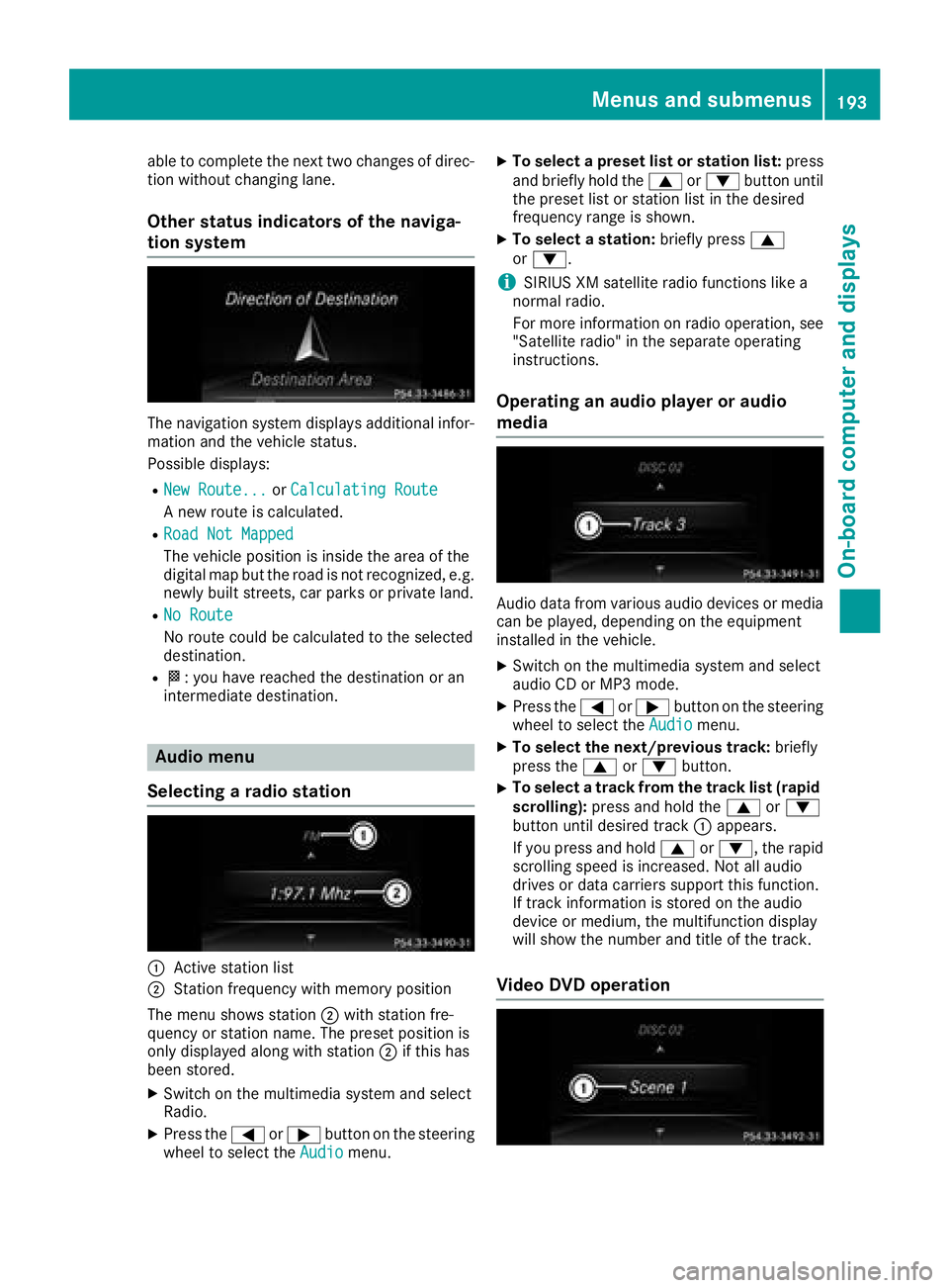
The navigation system displays additional infor-
mation and the vehicle status.
Possible displays: R
New Route... or Calculating Route
A new route is calculated. R
Road Not Mapped
The vehicle position is inside the area of the
digital map but the road is not recognized, e.g.
newly built streets, car parks or private land. R
No Route
No route could be calculated to the selected
destination. R
�K : you have reached the destination or an
intermediate destination.
Audio menu
Selecting a radio station
�C
Active station list
�D
Station frequency with memory position
The menu shows station �D with station fre-
quency or station name. The preset position is
only displayed along with station �D if this has
been stored. X
Switch on the multimedia system and select
Radio. X
Press the �Y or �e button on the steering
wheel to select the Audio menu. X
To select a preset list or station list: press
and briefly hold the �c or �d button until
the preset list or station list in the desired
frequency range is shown. X
To select a station: briefly press �c
or �d .
i SIRIUS XM satellite radio functions like a
normal radio.
For more information on radio operation, see
"Satellite radio" in the separate operating
instructions.
Operating an audio player or audio
media
Audio data from various audio devices or media
can be played, depending on the equipment
installed in the vehicle. X
Switch on the multimedia system and select
audio CD or MP3 mode. X
Press the �Y or �e button on the steering
wheel to select the Audio menu.X
To select the next/previous track: briefly
press the �c or �d button.X
To select a track from the track list (rapid
scrolling): press and hold the �c or �d
button until desired track �C appears.
If you press and hold �c or �d , the rapid
scrolling speed is increased. Not all audio
drives or data carriers support this function.
If track information is stored on the audio
device or medium, the multifunction display
will show the number and title of the track.
Video DVD operationMenus and submenus 193
On-board computer and displays Z
Page 238 of 334
General notes The multimedia system section in this Opera-
tor's Manual describes the basic principles for
operation. More information can be found in the
Digital Operator's Manual.
Important safety notes
G WARNING
If you operate information systems and com-
munication equipment integrated in the vehi-
cle while driving, you will be distracted from
traffic conditions. You could also lose control
of the vehicle. There is a risk of an accident.
Only operate the equipment when the traffic
situation permits. If you are not sure that this
is possible, park the vehicle paying attention
to traffic conditions and operate the equip-
ment when the vehicle is stationary.
You must observe the legal requirements for the
country in which you are currently driving when
operating the multimedia system.
The multimedia system calculates the route to
the destination without taking the following into
account, for example: R
traffic lights R
stop and yield signs R
parking or stopping restrictions R
road narrowing R
other road and traffic rules and regulations
The multimedia system may give incorrect nav-
igation recommendations if the actual street/
traffic situation does not correspond with the
digital map's data.
For example: R
a diverted route R
the road layout or the direction of a one-way
street has been changed
For this reason, you must always observe road
and traffic rules and regulations during your
journey. Road and traffic rules and regulations
always have priority over multimedia system
driving recommendations.
Navigation announcements are intended to
direct you while driving without diverting your
attention from the road and driving. Please always use this feature instead of con-
sulting the map display for directions. Looking
at the icons or map display can distract you from
traffic conditions and driving, and increase the
risk of an accident.
This equipment complies with FCC radiation
exposure limits set forth for uncontrolled equip-
ment and meets the FCC radio frequency (RF)
Exposure Guidelines in Supplement C to OET65.
This equipment has very low levels of RF energy
that is deemed to comply without maximum
permissive exposure evaluation (MPE). How-
ever, it is recommended to insta ll it at a distance
of
at least 8 inches (approx. 20 cm) between the
radiation source and a person's body (not
including limbs such as hands, wrists, feet and
legs).
G WARNING
Modifications to electronic components, their
software as well as wiring can impair their
function and/or the function of other net-
worked components. In particular, systems
relevant to safety could also be affected. As a
result, these may no longer function as inten-
ded and/or jeopardize the operating safety of
the vehicle. There is an increased risk of an
accident and injury.
Never tamper with the wiring as well as elec-
tronic components or their software. You
should have all work to electrical and elec-
tronic equipment carried out at a qualified
specialist workshop.
If you make any changes to the vehicle elec-
tronics, the general operating permit is ren-
dered invalid.
Function restrictions
For safety reasons, some functions are restric-
ted or unavailable while the vehicle is in motion.
You will notice this, for example, because either
you will not be able to select certain menu items
or a message will appear to this effect.236
Function restrictions
Multimedia system
Page 239 of 334
Operating system
Overview
General notes
! Do not use the space in front of the display
for storage. Objects placed here could dam-
age the display or impair its function. Avoid
any direct contact with the display surface.
Pressure on the display surface may result in
impairments to the display, which could be
irreversible.
Wearing polarized sunglasses may impair your
ability to read the display.
The display has an automatic temperature-con-
trolled switch-off feature. The brightness is
automatically reduced if the temperature is too
high. The display may temporarily switch off
completely.
Cleaning instructions
! Do not touch the display. The display has a
very sensitive high-gloss surface; there is a
risk of scratching. If you have to clean the
screen, however, use a mild cleaning agent
and a soft, lint-free cloth.
The display must be switched off and have
cooled down before you start cleaning. Do not
apply pressure to the display surface when
cleaning it, as this could cause irreversible dam-
age to the display.
Switching the multimedia system
on/off X
Press the �C control knob.
Adjusting the volume X
Turn the �C control knob.
The volume is adjusted: R
for the currently selected media source R
during traffic or navigation announcements R
in hands-free mode during a phone call
Switching the sound on or off X
Press the �c button on the control panel.
If the audio output is switched off, the status
line will show the �c symbol. If you switch the media source or set the volume, the sound
is automatically switched on.
i Navigation announcements will be heard
even if the sound is muted.
Functions The multimedia system has the following func-
tions: R
Radio mode R
Media mode with media search R
Sound systems R
Navigation system
COMAND: navigation via the hard drive
Audio 20: navigation via SD card R
Communication functions R
SIRIUS Weather (COMAND) R
Vehicle functions with system settings R
Favorites functions
Controller The controller in the center console lets you: R
select menu items on the display R
enter characters R
select a destination on the map R
save entries
The controller can be: R
turned 3 R
slid left or right 1 R
slid forwards or back 4R
slid diagonally 2 R
pressed briefly or pressed and held 7
Back button You can use the �8 button to exit a menu or to
call up the basic display of the current operating
mode. X
To exit the menu: briefly press the �8
button.
The multimedia system changes to the next
higher menu level in the current operating
mode. X
To call up the basic display: press the �8
button for longer than two seconds.
The multimedia system changes to the basic
display of the current operating mode.Operating system 237
Multimedia system Z
Page 303 of 334

The tire pressure monitor has a yellow warning
lamp in the instrument cluster for indicating
pressure loss or a malfunction. Whether the
warning lamp flashes or lights up indicates
whether a tire pressure is too low or the tire
pressure monitor is malfunctioning: R
if the warning lamp is lit continuously, the tire
pressure on one or more tires is significantly
too low. The tire pressure monitor is not mal-
functioning. R
if the warning lamp flashes for around a
minute and then remains lit constantly, the
tire pressure monitor is malfunctioning.
In addition to the warning lamp, a message
appears in the multifunction display. Observe
the information on display messages
( Y
page 221).
It may take up to ten minutes for a malfunction
of the tire pressure monitor to be indicated. A
malfunction will be indicated by the tire pres-
sure warning lamp flashing for approximately
one minute and then remaining lit. When the
malfunction has been rectified, the tire pressure
warning lamp goes out after a few minutes of
driving.
The tire pressure values indicated by the on-
board computer may differ from those meas-
ured at a gas station with a pressure gauge. The
tire pressures shown by the on-board computer
refer to those measured at sea level. At high
altitudes, the tire pressure values indicated by a
pressure gauge are higher than those shown by
the on-board computer. In this case, do not
reduce the tire pressures.
The operation of the tire pressure monitor can
be affected by interference from radio transmit-
ting equipment (e.g. radio headphones, two-way
radios) that may be being operated in or near the
vehicle.
Checking the tire pressure electroni-
cally X
Make sure that the SmartKey is in position 2
in the ignition lock ( Y
page 123).X
Press the �Y or �e button on the steering
wheel to select the Service menu.X
Press the �c or �d button to select
Tire Pressure .X
Press the �v button.
The current tire pressure of each tire is shown
in the multifunction display. If the vehicle has been parked for over
20 minutes, the Tire pressures will be
displayed after driving a few minutes
message appears.
After a teach-in process, the tire pressure mon-
itor automatically detects new wheels or new
sensors. As long as a clear allocation of the tire
pressure value to the individual wheels is not
possible, the Tire Pressure Monitor Active
display message is shown instead of the tire
pressure display. The tire pressures are already
being monitored.
If an emergency spare wheel is mounted, the
system may continue to show the tire pressure
of the wheel that has been removed for a few
minutes. If this occurs, note that the value dis-
played for the position where the spare wheel is
mounted is not the same as the current tire
pressure of the emergency spare wheel.
Tire pressure monitor warning mes-
sages If the tire pressure monitor detects a pressure
loss in one or more tires, a warning message is
shown in the multifunction display. The yellow
tire pressure warning lamp then lights up. R
If the Correct Tire Pressure message
appears in the multifunction display, the tire
pressure in at least one tire is too low. The tire
pressure must be corrected when the oppor-
tunity arises. R
If the Check Tires message appears in the
multifunction display, the tire pressure in one
or more tires has dropped significantly. The
tires must be checked. R
If the Warning Tire Malfunction message
appears in the multifunction display, the tire
pressure in one or more tires is dropping sud-
denly. The tires must be checked.
Observe the instructions and safety notes in the
display messages in the "Tires" section
( Y
page 221).
If the wheel positions on the vehicle are rotated,
the tire pressures may be displayed for the
wrong positions for a short time. This is rectified
after a few minutes of driving, and the tire pres-
sures are displayed for the correct positions. Tire pressure 301
Wheels and tires Z
Page 304 of 334
Restarting the tire pressure monitor When you restart the tire pressure monitor, all
existing warning messages are deleted and the
warning lamps go out. The monitor uses the cur-
rently set tire pressures as the reference values
for monitoring. In most cases, the tire pressure
monitor will automatically detect the new refer-
ence values after you have changed the tire
pressure. However, you can also define refer-
ence values manually as described here. The tire
pressure monitor then monitors the new tire
pressure values. X
Set the tire pressure to the value recommen-
ded for the corresponding driving situation on
the Tire and Loading Information placard on
the driver's side B-pillar ( Y
page 295).
You can find more tire pressure values for
various operating conditions in the tire pres-
sure table inside the fuel filler flap
( Y
page 295).X
Make sure that the tire pressure is correct on
all four wheels. X
Make sure that the SmartKey is in position 2
in the ignition lock. X
Press the �Y or �e button on the steering
wheel to select the Service menu.X
Press the �c or �d button to select
Tire Pressure .X
Press the �v button.
The multifunction display shows the current
tire pressure for the individual tires or the
Tire pressures will be displayed
after driving a few minutes message.X
Press the �d button.
The Use Current Pressures as New Ref‐
erence Values message appears in the mul-
tifunction display.
If you wish to confirm the restart: X
Press the �v button.
The Tire Press. Monitor Restarted mes-
sage appears in the multifunction display.
After driving for a few minutes, the system
checks whether the current tire pressures are
within the specified range. The new tire pres-
sures are then accepted as reference values
and monitored.
If you wish to cancel the restart: X
Press the �8 button.
The tire pressure values stored at the last
restart will continue to be monitored. Radio type approval for the tire pres-
sure monitor Country Radio type approval number
USA FCC ID: MRXMW2433A
FCC ID: MRXGG4
FCC ID: MRXMC34MA4
Canada IC: 2546A-MW2433A
IC: 2546A-GG4
IC: 2546A-MC34MA4
Loading the vehicle
Instruction labels for tires and loads
G WARNING
Overloaded tires can overheat, causing a
blowout. Overloaded tires can also impair the
steering and driving characteristics and lead
to brake failure. There is a risk of accident.
Observe the load rating of the tires. The load
rating must be at least half of the GAWR of
your vehicle. Never overload the tires by
exceeding the maximum load.
Two instruction labels on your vehicle show the
maximum possible load.
(1) The Tire and Loading Information placard is
on the B-pillar on the driver's side. The Tire
and Loading Information placard shows the
maximum permissible number of occu-
pants and the maximum permissible vehicle
load. It also contains details of the tire sizes
and corresponding pressures for tires
mounted at the factory.
(2) The vehicle identification plate is on the B-
pillar on the driver's side. The vehicle iden-
tification plate informs you of the gross
vehicle weight rating. It is made up of the
vehicle weight, all vehicle occupants, the
fuel and the cargo. You can also find infor-
mation about the maximum gross axle
weight rating on the front and rear axle.
The maximum gross axle weight rating is
the maximum weight that can be carried by
one axle (front or rear axle). Never exceed
the maximum load or the maxi mum g ross
a
xle weight rating for the front or rear axle.302
Loading the vehicle
Wheels and tires
Page 323 of 334
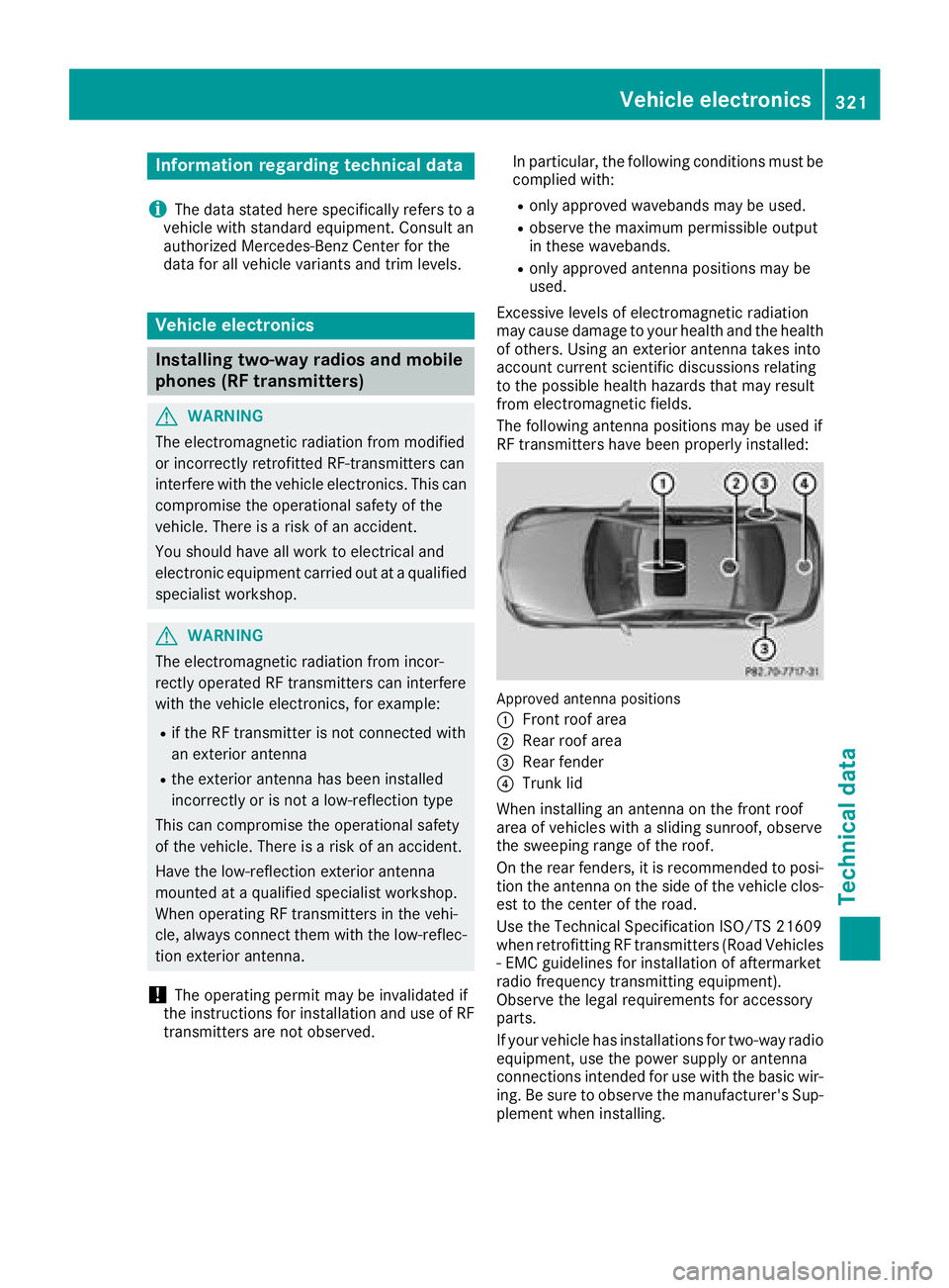
Information regarding technical data
i The dat a state d her e specifically refers to a
vehicl e wit h standard equipment. Consult an
authorize d Mercedes-Ben z Cente r for th e
dat a for all vehicl e variants and trim levels.
Vehicle electronics
Installing two-way radios and mobile
phones (RF transmitters)
G WARNIN G
The electromagneti c radiation from modifie d
or incorrectl y retrofitte d RF-transmitters can
interfere wit h th e vehicl e electronics . This can
compromise th e operational safet y of th e
vehicle. Ther e is a ris k of an accident.
You should hav e all wor k to electrical and
electronic equipmen t carried out at a qualified
specialist workshop.
G WARNIN G
The electromagneti c radiation from incor-
rectl y operate d RF transmitters can interfere
wit h th e vehicl e electronics , for example:R
if th e RF transmitte r is no t connecte d wit h
an exterio r antennaR
th e exterio r antenna has been installed
incorrectl y or is no t a low-reflection typ e
This can compromise th e operational safet y
of th e vehicle. Ther e is a ris k of an accident.
Hav e th e low-reflection exterio r antenna
mounte d at a qualified specialist workshop.
When operating RF transmitters in th e vehi-
cle , always connec t them wit h th e low-reflec -
tion exterio r antenna.
! The operating permit may be invalidated if
th e instruction s for installation and use of RF
transmitters are no t observed. In particular, th e followin g condition s must be
complied with: R
only approve d wavebands may be used. R
observ e th e maximum permissible output
in these wavebands. R
only approve d antenna position s may be
used.
Excessiv e levels of electromagneti c radiation
may caus e damag e to your healt h and th e healt h
of others. Using an exterio r antenna takes int o
accoun t curren t scientific discussion s relating
to th e possible healt h hazards that may result
from electro magneti c fi
elds.
The followin g antenna position s may be used if
RF transmitters hav e been properly installed:
Approved antenna position s
�C
Fron t roo f area�D
Rear roo f area�
Page 324 of 334

Deviations with respect to frequency bands,
maximum transmission outputs or antenna
positions must be approved by Mercedes-Benz.
The maximum transmission output (PEAK) at the
base of the antenna must not exceed the fol-
lowing values:
Frequency band Maximum
transmission
output
Short wave
3 - 54 MHz 100 W
4 m waveband
74 - 88 MHz 30 W
2 m waveband
144 - 174 MHz 50 W
Trunked radio system/
Tetra
380 - 460 MHz 10 W
70 cm waveband
400 - 460 MHz 35 W
Mobile communications
(2G/3G/4G) 10 W
The following can be used in the vehicle without
restrictions: R
RF transmitters with a maximum transmis-
sion output of up to 100 mW R
RF transmitters with transmitter frequencies
in the 380 - 410 MHz waveband and a maxi-
mum transmission output of up to 2 W
(trunked radio/Tetra) R
Mobile phones (2G/3G/4G)
There is no restriction for antenna positions on
the outside of the vehicle for the following fre-
quency bands: R
Trunked radio system/Tetra R
70 cm waveband R
2G/3G/4G Identification plates
Vehicle identification plate with vehi-
cle identification number (VIN) X
Open the front left-hand door.
You will see vehicle identification plate �C .
Example: vehicle identification plate (USA only)
�C
VIN �D
Vehicle model
Example: vehicle identification plate (Canada only)
�C
VIN
�D
Paint code
i The data shown on the vehicle identification
plate is used only as an example. This data is
different for every vehicle and can deviate322
Identification plates
Technical data