2018 MERCEDES-BENZ AMG GT R-ROADSTER diagram
[x] Cancel search: diagramPage 64 of 473
Key
Overview of
key functions &
WARNING Risk of accident and inju ry
due tochildren left unat tended in the
ve hicle
If ch ildren are left unat tended in theve hicle,
th ey could:
R open doo rs,th ereby endangering other
persons or road users.
R get out of theve hicle and be hit by
oncoming traf fic.
R ope rate ve hicle equipment and become
trapped, forex ample.
In addition, children could also set theve hi‐
cle in motion, forex ample, by:
R releasing the parking brake.
R shifting the automatic transmission out of
park position jor shifting manual trans‐
mission into neutral.
R starting the engine. #
When leaving theve hicle, alw aysta ke
th eke y with you and lock theve hicle. #
Never lea vechildren and animals unat‐
te nded in theve hicle. #
Keep theve hicle key out of reach of
ch ildren. *
NO
TEDama getotheke y caused by
magnetic fields #
Keep theke yaw ay from strong mag‐
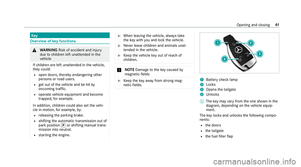
netic fields. 1
Battery check lamp
2 Locks
3 Opens theta ilgate
4 Unloc ks
% The key may vary from the one shown in the
diagram, depending on theve hicle equip‐
ment.
The key loc ksand unlo cksth efo llowing compo‐
nents:
R the doors
R theta ilgate
R the fuel filler flap Opening and closing
61
Page 220 of 473
#
Select Start Record .
Measu rement is incremental, in steps of
50 km/h toast andstill. If the braking proce‐
dure is star ted e.g. at a speed of 160 km/h,
measurement starts as soon as 150 km/h
has been reached.
St oring and calling up measurement values
When a measurement has been comple ted or
cancelled, the measured time can be stored. #
After a measu rement, select Save measure-
ment? .
The stored measurements can be displa yed via
th eHistory menu item.
Editing measu rements #
Select History . #
Highlight the desired measurement. #
Select Üoptions. #
Select Weather orDelete.
% The measurements can be displa yedby cate‐
gor y,e.g. acceleration measurements, by
applying a filter. Calling up
thete lemetry display Multimedia sy
stem:
4 Vehicle 5
TRACK PACE 5
Telemetry
The telemetry display sho wscurrent vehicle data
as a digital value and as a diagram. Uptofour
parame ters can be selected that are tobe
shown in the displa y.
Fo rex ample:
R engine speed
R wheel angle
R speed
R steering angle #
Set the desired parame ters. #
Set the time.
The set parame ters are evaluated in the dia‐
gram forth e time set.
% The time can range from a minimum of
30 seconds toa maximum of 20 minutes. Configuring AMG TR
ACKPA CE Re
quirements:
To use the TRACK PACE app:
R the TRA CKPACE app is ins talled on the
mobile end device.
R the mobile end device is connected tothe
multimedia sy stem via Wi-Fi.
Multimedia sy stem:
4 Vehicle 5
TRACK PACE 5
Options
Setting driver profiles #
Select Driver Profile. #
Create a new driver profile.
or #
Select an existing driver profile.
The driver profile is activated.
% Trac ks, laps and times driven are assigned to
th e active driver profile while driving. For an
ex act evaluation of your driving style, you
should alw ays drive with an active driver pro‐
fi le. Multimedia sy
stem 217
Page 345 of 473
Blown fuses must be
replaced with fuses of the
same rating, which you can recognise bythe col‐
our and fuse rating. The fuse ratings and fu rther
information tobe obser ved are lis ted in the fuse
assignment diagram.
Fu se assignment diag ram: onthe fuse box in
th e load compartment .
* NO
TEDama geor malfunctions caused
by moisture Moisture may cause dama
getothe electrical
sy stem or cause it tomalfunction. #
When the fuse box is open, make sure
th at no moisture can enter the fuse
box. #
When closing the fuse box, make sure
th at the seal of the lid is positioned cor‐
re ctly on the fuse box. If
th e newly inser ted fuse also blo ws, ha vethe
cause traced and rectified at a qualified special‐
ist workshop, e.g. a Mercedes-Benz Service
Centre. Ensure
thefo llowing before replacing a fuse:
R The vehicle is secured against rolling away.
R All electrical consumers are switched off.
R The ignition is switched off.
The electrical fuses are located in various fuse
bo xes:
R Fuse box in the front passenger foot we ll
(/ page 342)
R Fuse box in the load compartment on the
left-hand side of theve hicle, when vie wed in
th e direction of tr avel Opening and closing
the fuse box in the front
passenger foot we ll Obser
vethe no tes on electrical fuses
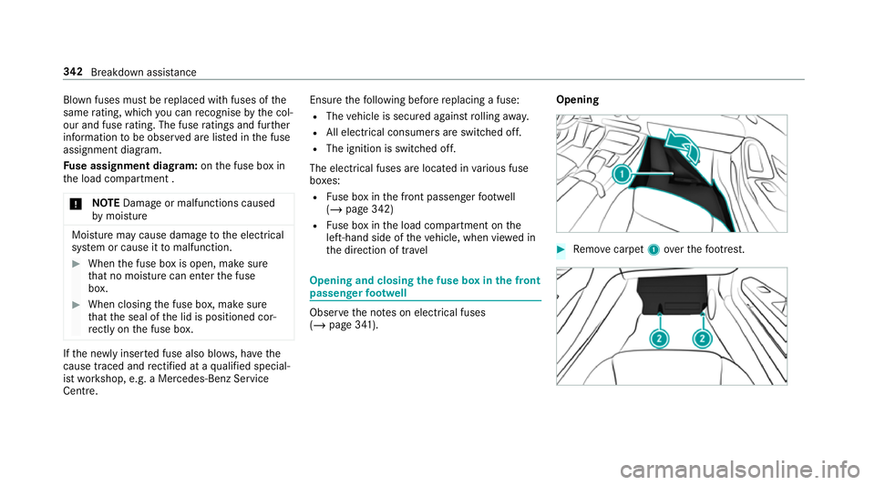
(/ page 341). Opening #
Remo vecarpet 1over thefo ot re st. 342
Breakdown assis tance
Page 346 of 473
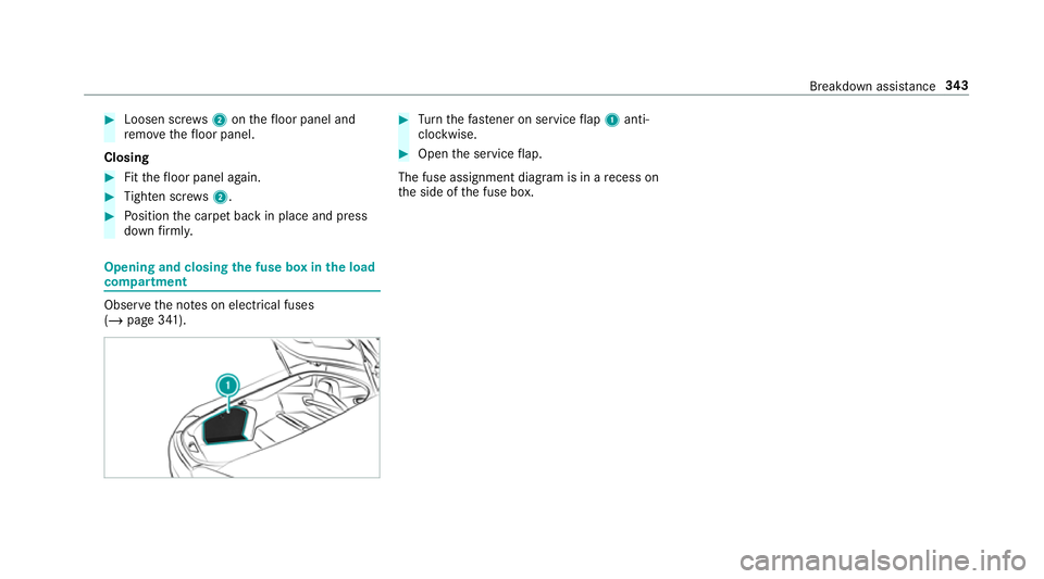
#
Loosen scr ews2 onthefloor panel and
re mo vethefloor panel.
Closing #
Fitthefloor panel again. #
Tighten scr ews2. #
Position the carpet back in place and press
down firm ly. Opening and closing
the fuse box in the load
compa rtment Obse
rveth e no tes on electrical fuses
(/ page 341). #
Turn thefast ener on service flap 1 anti-
clo ckwise. #
Open the service flap.
The fuse assignment diagram is in a recess on
th e side of the fuse box. Breakdown assis
tance 343
Page 448 of 473
Fa
ult message
see Displ aymessa ge
Favo urites
Ad ding .................................................2 00
Calling up ............................................ 200
Deleting ............................................... 201
Moving ................................................. 201
Overview ............................................. 200
Re naming ............................................ 200
Fi lling station sear ch
St arting automatic sear ch................... 223
Switching au tomatic search on/off ..... 229
Using auto matic search....................... 229
Fire extinguisher ..................................... 325
Fi rs t-aid kit (soft sided) .......................... 325
Flat towing
see Tow- bar sy stem
Flat tyre ....................................................3 25
MOExtended tyres ............................... 326
No tes .................................................. 325
TIREFIT kit ...........................................3 27
Wheel change ...................................... 356
Floor mats .................................................. 97Fo
il co vering
Ra dar sensors ...................................... 13 6
Fr ee software ............................................ 26
Fr equency band
Dialling (on-board computer) .............. .179
Fr ont airbag (driver, front passenger) .....35
Fr ont and reve rsing camera .................... 161
Fr ont camera
Fu nction ............................................... 161
Fr ont spoiler
see Aerodynamics profile
Fu el .......................................................... .369
Ad ditives .............................................3 69
E10 ...................................................... 367
Fu elreser ve ........................................ 369
Pe trol ................................................... 367
Quality (p etro l) .................................... .367
Re fuelling ............................................. 12 5
Sulphur content ................................... 367
Ta nk content ....................................... 369
Fu el consum ption
On-board computer ............................ .177 Fu
nction seat
see Door cont rol panel
Fu ses ........................................................ 341
Before replacing a fuse ........................ 341
Fu se assignment diagram .................... 341
Fu se box in the front passenger foot‐
we ll ...................................................... 342
Fu se box in the load compartment ...... 343
No tes ................................................... 341 G
G-me ter (on-board co mputer, Per‐
fo rm ance menu) ....................................... 174
Garage door opener Clearing the memory ........................... 131
Opening or closing the door ................1 30
Programming buttons .......................... 12 8
Ra dio equipment appr oval numbers .... 131
Re solving problems ............................. 12 9
Synchronising thero lling code ............ 12 9
Gear display (on-board computer, Per‐
fo rm ance menu) ....................................... 174
Gearshift recommendation .....................124 Index
445