2018 MERCEDES-BENZ A-CLASS SALOON lights
[x] Cancel search: lightsPage 50 of 621

#
Stow objects in a suitable place. Re
versing the PRE- SAFE®
sy stem measures If an accident did not occur,
the pre-em ptive
measures that we retak en are reve rsed.
Yo u will need toper form certain settings your‐
self. #
Ifth e seat belt pre-tensioning is not reduced,
mo vethe seat backrest back slightl y.
The locking mechanism releases. Fu
nction of PRE-SAFE ®
PLUS (anticipatory
occupant pr otection plus) PRE-
SAFE®
PLUS can de tect cer tain impacts,
particular lyan imminent rear impact, and take
pre-em ptive measures toprotect theve hicle
occupants. These measures cannot necessarily
pr eve nt an imminent impact. PRE-SAFE
®
PLUS can implement thefo llowing
measures independently of each other:
R Tightening the seat belts on the driver's seat
and front passenger seat.
R Activating there ar hazard warning lights at a
higher flashing frequenc y.
R Increasing brake pressure when theve hicle
is stationar y.This brake application is cancel‐
led automatically when theve hicle pulls
aw ay.
If an accident did not occur, the pre-em ptive
measures that we retake n are reve rsed.
Sy stem limitations
The sy stem will not initiate any action in thefo l‐
lowing situations:
R when reve rsing
or
R when theve hicle is towing a trailer and there
is a risk of a rear impact The sy
stem will not initiate any braking applica‐
tion in thefo llowing situations:
R whilst driving
or
R when entering or exiting a parking space
while using Active Parking Assist Safely transporting
children in theve hicle Alw
ays obser vewhen children are tr avelling
in theve hicle %
Also strictly obser vethe saf ety no tesfo rthe
specific situation. In this wa yyo u can recog‐
nise po tential risks and avoid dangers if chil‐
dren are tr avelling in theve hicle
(/ page 48).
Be diligent
Bear in mind that neglecting tosecure a child in
th ech ild restra int sy stem may ha veserious con‐
sequences. Alw ays be diligent in securing a child
carefully before every journe y. Occupant saf
ety47
Page 78 of 621

#
Todeactivate: pressthe& button on the
ke y twice in quick succession.
The battery check lamp of theke yflashes
twice brief lyand lights up once. #
Toactivate: press any button on thekey.
% When theve hicle is star ted with theke y in
th estow age compartment of the cent recon‐
sole, theke y functions are automatical ly
activated (/ page157). Re
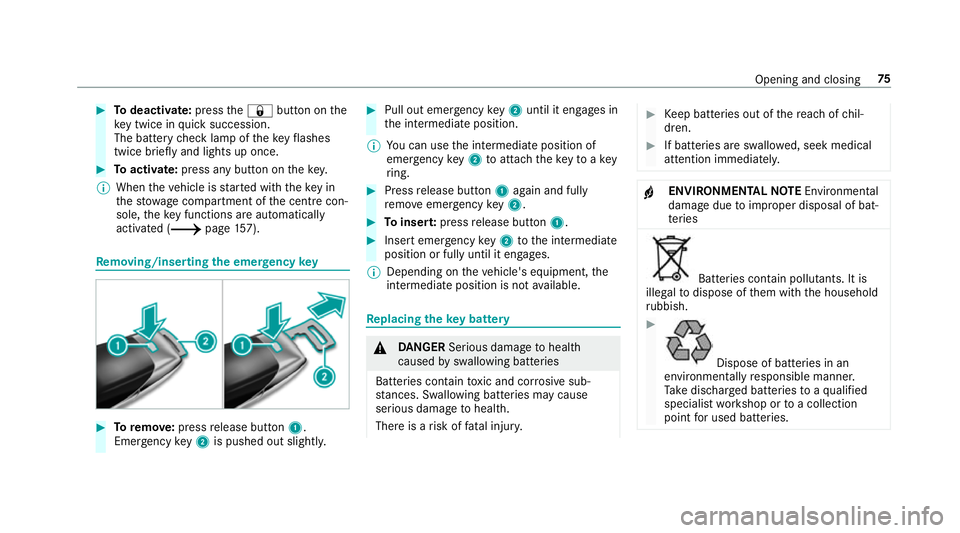
moving/inserting the eme rgency key #
Toremo ve:press release button 1.
Emer gency key2 is pushed out slight ly. #
Pull out emer gency key2 until it en gage s in
th e intermediate position.
% You can use the intermediate position of
emer gency key2 toattach theke yto akey
ri ng. #
Press release button 1again and fully
re mo veemer gency key2. #
Toinser t:press release button 1. #
Insert emer gency key2 tothe intermediate
position or fully until it engages.
% Depending on theve hicle's equipment, the
intermediate position is not available. Re
placing the key battery &
DANG ER Serious damage tohealth
caused byswallowing batteries
Batteries contain toxic and cor rosive sub‐
st ances. Swallowing bat teries may cause
serious damage tohealth.
There is a risk of fata l injur y. #
Keep batteries out of there ach of chil‐
dren. #
If batteries are swallo wed, seek medical
attention immediately. +
ENVIRONMEN
TALNO TEEnvironmental
dama gedue toimproper disposal of bat‐
te ries Batteries conta
in pollutants. It is
illegal todispose of them with the household
ru bbish. #
Dispose of batteries in an
environmen tally responsible manner.
Ta ke dischar ged batteries toaqu alified
specialist workshop or toa collection
point for used batteries. Opening and closing
75
Page 81 of 621

Un
locking/opening the doors from the inside #
United Kingdom onl y:obser vethe no tes on
th e additional door lock (/ page77). #
Pull door handle 1. Centrally locking and unlocking
theve hicle
from the inside #
Tounlo ck:press button 1. #
Tolock: press button 2.
The indicator lamp lights up.
This does not lock or unlock the fuel filler flap. The
vehicle is not unloc ked:
R Ifyo u ha veloc kedth eve hicle using thekey.
R Ifyo u ha veloc kedth eve hicle using KEY‐
LESS-GO. Locking/unlocking
theve hicle with a Digital
Ve hicle Key Re
quirements:
R one of thefo llowing versions of the Digital
Ve hicle Key is available:
- suitable mobile phone
- Digital Vehicle Keyst icker
R theve hicle is equipped with the "Digital Vehi‐
cle Key" function.
R the "Digital Vehicle Key" function is activated
via Mercedes me connec t:http://
www.mercedes.me.
R the mobile phone must be suf ficiently
ch arge d.
% You can check the suitability of your mobile
phone byentering the phone number at
http://www.mercedes.me. 78
Opening and closing
Page 84 of 621

Ac
tivating/deactivating the automatic lo ck‐
ing feature The
vehicle is loc ked automatically when the
ignition is switched on and the wheels are turn‐
ing fast erthan walking pace. #
Toactivate: press and hold button 2for
appr oximately five seconds until an acoustic
signal sounds. #
Todeactivate: press and hold button 1for
appr oximately five seconds until an acoustic
signal sounds.
When theve hicle is loc ked automatically, the
indicator lamp in button 2lights up.
In thefo llowing situations, there is a danger of
being loc ked out when the function is activated:
R While theve hicle is being tow star ted/
pushed.
R The vehicle is being tested on the dynamom‐
et er. Locking/unlocking
theve hicle with the
emer gency key Locking/unlocking
the driver's door with the
emer gency key
% Ifyo u wish tolock theve hicle entirely using
th e emer gency key,firs t press the button for
locking from the inside while the driver's
door is open. Then proceed tolock the driv‐
er's door using the emer gency key. #
Insert the emer gency key as far as it will go
into opening 1inthe co ver. #
Pull and hold the door handle. #
Pull the co ver on the emer gency key as
st ra ight as possible away from theve hicle
until it releases. #
Release the door handle. Opening and closing
81
Page 109 of 621

#
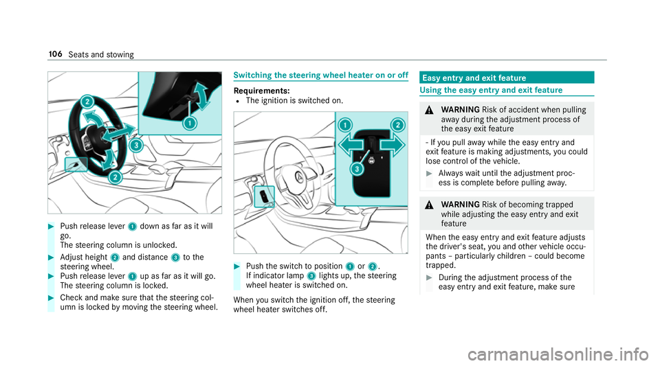
Push release le ver1 down as far as it will
go.
The steering column is unloc ked. #
Adjust height 2and di stance 3tothe
st eering wheel. #
Push release le ver1 up as far as it will go.
The steering column is loc ked. #
Check and make sure that thesteering col‐
umn is loc kedby moving thesteering wheel. Switching
thest eering wheel heater on or off Re
quirements:
R The ignition is switched on. #
Push the switch toposition 1or2.
If indicator lamp 3lights up, thesteering
wheel heater is switched on.
When you swit ch the ignition off, thesteering
wheel heater switches off. Easy entry and
exitfeature Using
the easy entry and exitfeature &
WARNING Risk of accident when pulling
aw ay during the adjustment process of
th e easy exitfeature
‑ If you pull away while the easy entry and
ex itfeature is making adjustments, you could
lose cont rol of theve hicle. #
Alw ayswa it until the adjustment proc‐
ess is comple tebefore pulling away. &
WARNING Risk of becoming trapped
while adjusting the easy entry andexit
fe ature
When the easy entry andexitfeature adjusts
th e driver's seat, you and other vehicle occu‐
pants – particularly children – could become
trapped. #
During the adjustment process of the
easy entry andexitfeature, make sure 106
Seats and stowing
Page 124 of 621

Using
the11 5 V soc ket in the rear &
DANG ER Risk of fata l injury due todam‐
aged connecting cables or soc kets
If a suitable device is connected, the11 5 V
soc ket will be car rying a high voltage. If the
connecting cable or the11 5 V soc ket is
pulled out of the trim or is damaged or wet,
yo u could recei vean electric shoc k. #
Use only connecting cables that are dry
and free of damage. #
When the ignition is switched off,
ensure that the11 5 V soc ket is dr y. #
Ifth e11 5 V soc ket is dama ged or gets
pulled out of the trim, immediately ha ve
th e soc ketch ecked or replaced at a
qu alified specialised workshop. #
Never plug the connecting cable into a
11 5 V soc ketth at is damaged or has
been pulled out of the trim. &
DANG ER Risk of fata l injury due toincor‐
re ct handling of the soc ket
Yo u could recei vean electric shock:
R ifyo ure ach into the soc ket.
R ifyo u insert unsuitable devices or objects
into the soc ket. #
Do not reach into the soc ket. #
Only connect suitable devices tothe
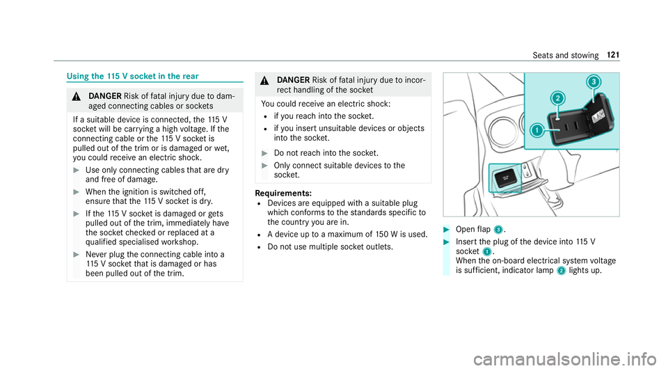
soc ket. Re
quirements:
R Devices are equipped with a suitable plug
which con form sto thest andards specific to
th e count ryyou are in.
R A device up toa maximum of 150 W is used.
R Do not use multiple soc ket outlets. #
Open flap 3. #
Insert the plug of the device into 115 V
soc ket1.
When the on-board electrical sy stem voltage
is suf ficient, indicator la mp2lights up. Seats and
stowing 121
Page 125 of 621

Using
the 230 V soc ket in the rear &
DANG ER Risk of fata l injury due todam‐
aged connecting cables or soc kets
When a suitable device is connected, the
230 V power soc ket will be car rying a high
vo ltage. You could recei vean electric shock
if th e connecting cable or the 230 V po wer
soc ket is pulled out of the trim or is damaged
or we t. #
Use only connecting cables that are dry
and free of damage. #
When the ignition is switched off, make
sure that the 230 V po wer soc ket is dr y. #
Immedia tely ha ve the 230 V po wer
soc ketch ecked or replaced at a quali‐
fi ed specialised workshop if it is dam‐
aged or has been pulled out of the trim. #
Never plug the connecting cable into a
230 V po wer soc ketth at is damaged or
has been pulled out of the trim. &
DANG ER Risk of fata l injury due toincor‐
re ct handling of the soc ket
Yo u could recei vean electric shock:
R ifyo ure ach into the soc ket.
R ifyo u insert unsuitable devices or objects
into the soc ket. #
Do not reach into the soc ket. #
Only connect suitable devices tothe
soc ket. Re
quirements:
R Devices are equipped with a suitable plug
which con form sto thest andards specific to
th e count ryyou are in.
R A device up toa maximum of 150 W is used.
R Do not use multiple soc ket outlets. #
Open flap 3. #
Insert the plug of the device into 230 V
soc ket1.
When the on-board electrical sy stem voltage
is suf ficient, indicator la mp2lights up. 12 2
Seats and stowing
Page 130 of 621

Exterior lighting
Note
s onchanging the lights when driving
abroad It is not necessary
tochange the headlamps.
The legal requirements are also met in countries
in which traf fic drives on theot her side of the
ro ad. Information about lighting sy
stems and your
re sponsibility The
various lighting sy stems of theve hicle are
only aids. The driver of theve hicle is responsible
fo r cor rect vehicle illumination in accordance
with the pr evailing light and visibility conditions,
legal requirements and traf fic situation. Light switch
Ope
rating the light switch 1
W Left pa rking light
2 X Right parking light
3 T Standing lights and licence plate light‐
ing
4 Ã Automatic driving lights (prefer red light
switch position) 5
L Low beam/high beam
6 R Switches there ar fog lights on or off
When low beam is activated, the indicator lamp
fo rth est anding lights Tis deactivated and
re placed bythe low beam indicator lamp L. #
Alw ays park your vehicle safely and in a well-
lit area, in accordance with there leva nt le gal
st ipulations.
* NO
TEBattery discharging byoperating
th est anding lights Operating
thest anding lights over a period of
hours puts a stra in on the batter y. #
Where possible, switch on the
ri ght X or left Wparking light. In
the case of se vere battery discharging, the
st anding lights or parking lights are automati‐
cally swit ched off tofacilitate the next engine
st art.
The exterior lighting (e xcept standing and park‐
ing lights) swit ches off automatically when the
driver's door is opened. Light and sight
127