Page 397 of 514

3976-3. Do-it-yourself maintenance
LS500_OM_OM50F54U_(U) 6
Maintenance and care
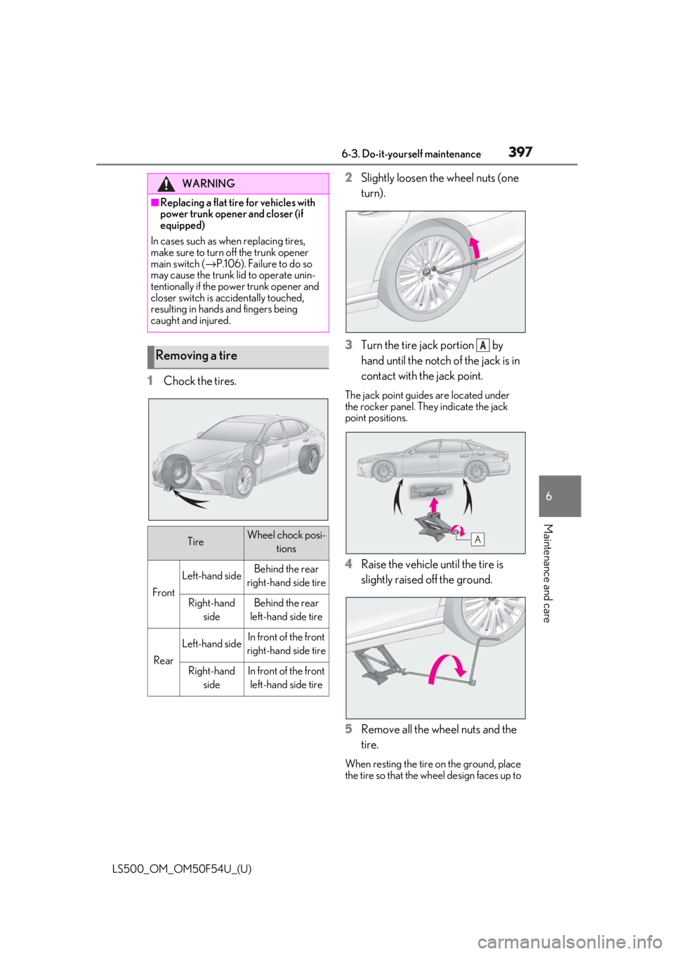
1 Chock the tires. 2 Slightly loosen the wheel nuts (one
turn).
3 Turn the tire jack portion by
hand until the notch of the jack is in
contact with the jack point. The jack point guides are located under
the rocker panel. They indicate the jack
point positions.
4 Raise the vehicle until the tire is
slightly raised off the ground.
5 Remove all the wheel nuts and the
tire. When resting the tire on the ground, place
the tire so that the wheel design faces up to WARNING■
Replacing a flat tire for vehicles with
power trunk opener and closer (if
equipped)
In cases such as when replacing tires,
make sure to turn off the trunk opener
main switch ( → P.106). Failure to do so
may cause the trunk lid to operate unin-
tentionally if the power trunk opener and
closer switch is accidentally touched,
resulting in hands and fingers being
caught and injured.
Removing a tire
Tire Wheel chock posi-
tions
Front Left-hand side Behind the rear
right-hand side tire
Right-hand
side Behind the rear
left-hand side tire
Rear Left-hand side In front of the front
right-hand side tire
Right-hand
side In front of the front
left-hand side tire A
Page 410 of 514

410 7-1. Essential information
LS500_OM_OM50F54U_(U) 7-1.Essential information
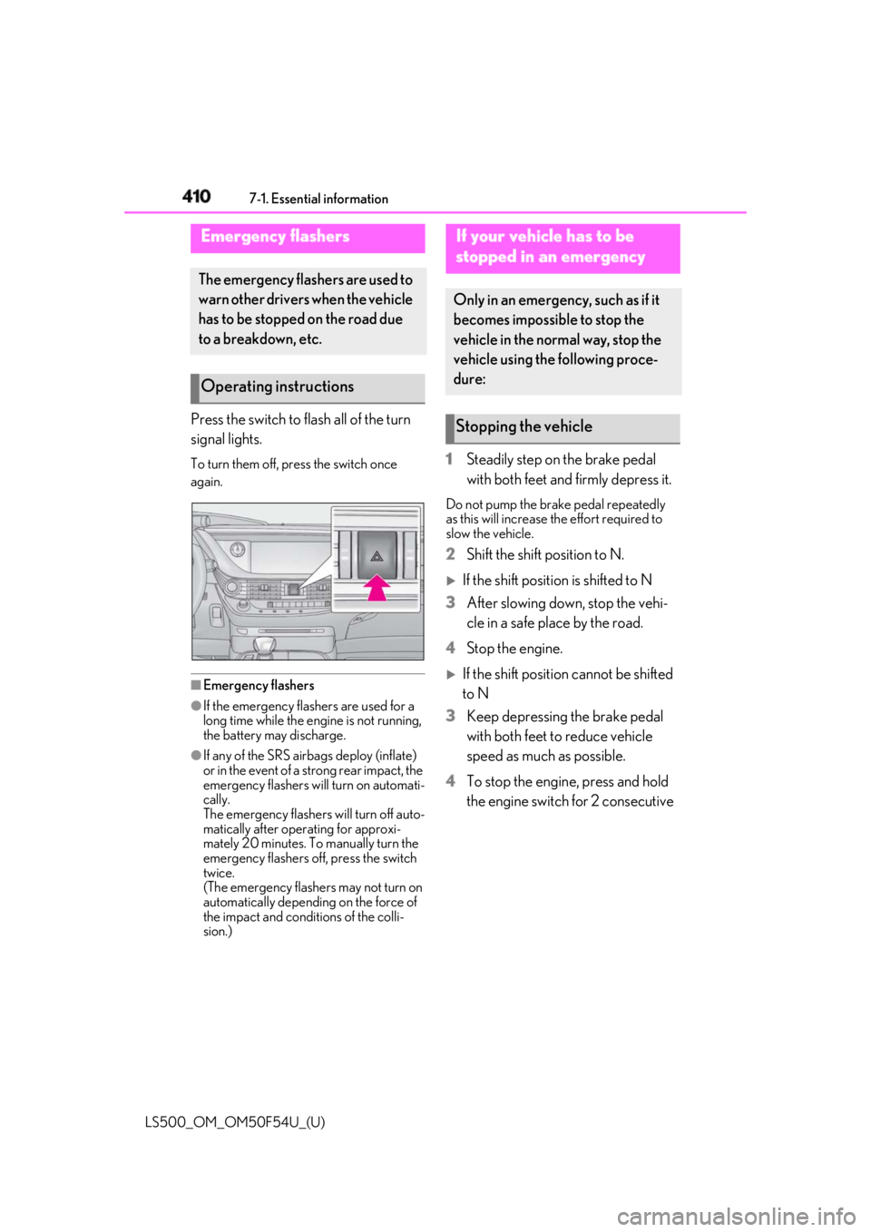
Press the switch to flash all of the turn
signal lights. To turn them off, press the switch once
again.
■
Emergency flashers●
If the emergency flashers are used for a
long time while the engine is not running,
the battery may discharge.●
If any of the SRS airbags deploy (inflate)
or in the event of a strong rear impact, the
emergency flashers will turn on automati-
cally.
The emergency flashers will turn off auto-
matically after operating for approxi-
mately 20 minutes. To manually turn the
emergency flashers off, press the switch
twice.
(The emergency flashers may not turn on
automatically depending on the force of
the impact and conditions of the colli-
sion.) 1 Steadily step on the brake pedal
with both feet and firmly depress it. Do not pump the brake pedal repeatedly
as this will increase the effort required to
slow the vehicle.
2 Shift the shift position to N.
If the shift position is shifted to N
3 After slowing down, stop the vehi-
cle in a safe place by the road.
4 Stop the engine.
If the shift position cannot be shifted
to N
3 Keep depressing the brake pedal
with both feet to reduce vehicle
speed as much as possible.
4 To stop the engine, press and hold
the engine switch for 2 consecutive Emergency flashers The emergency flashers are used to
warn other drivers when the vehicle
has to be stopped on the road due
to a breakdown, etc.
Operating instructions If your vehicle has to be
stopped in an emergency Only in an emergency, such as if it
becomes impossible to stop the
vehicle in the normal way, stop the
vehicle using the following proce-
dure:
Stopping the vehicle
Page 415 of 514

4157-2. Steps to take in an emergency
LS500_OM_OM50F54U_(U) 7
When trouble arises wheels, drive train, axles, steering and
brakes must be in good condition.
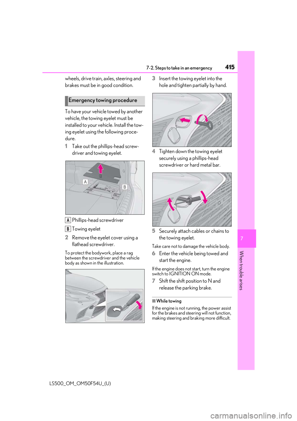
To have your vehicle towed by another
vehicle, the towing eyelet must be
installed to your vehicle. Install the tow-
ing eyelet using the following proce-
dure.
1 Take out the phillips-head screw-
driver and towing eyelet.
Phillips-head screwdriver
Towing eyelet
2 Remove the eyelet cover using a
flathead screwdriver.To protect the bodywork, place a rag
between the screwdriver and the vehicle
body as shown in the illustration. 3 Insert the towing eyelet into the
hole and tighten partially by hand.
4 Tighten down the towing eyelet
securely using a phillips-head
screwdriver or hard metal bar.
5 Securely attach cables or chains to
the towing eyelet. Take care not to damage the vehicle body.
6 Enter the vehicle being towed and
start the engine. If the engine does not start, turn the engine
switch to IGNITION ON mode.
7 Shift the shift position to N and
release the parking brake. ■
While towing
If the engine is not running, the power assist
for the brakes and steering will not function,
making steering and braking more difficult.Emergency towing procedure
A
B
Page 416 of 514
416 7-2. Steps to take in an emergency
LS500_OM_OM50F54U_(U) Fluid leaks under the vehicle.
(Water dripping from the air condi-
tioning after use is normal.)
Flat-looking tires or uneven tire
wear
Engine coolant temperature gauge
needle continually points higher
than normal.
Changes in exhaust sound
Excessive tire squeal when corner-
ing
Strange noises related to the sus-
pension system
Pinging or other noises related to
the engine
Engine missing, stumbling or run-
ning roughly
Appreciable loss of power
Vehicle pulls heavily to one side
when braking Vehicle pulls heavily to one side
when driving on a level road
Loss of brake effectiveness, spongy
feeling, pedal almost touches the
floor
If you think something is
wrong If you notice any of the following
symptoms, your vehicle probably
needs adjustment or repair. Con-
tact your Lexus dealer as soon as
possible.
Visible symptoms
Audible symptoms
Operational symptoms
Page 432 of 514

432 7-2. Steps to take in an emergency
LS500_OM_OM50F54U_(U) Take your vehicle to the nearest Lexus
dealer or authorized tire dealer as
soon as possible if any tire goes flat. The vehicle can be driven for a maximum
of 100 miles (160 km) at a speed below 50
mph (80 km/h) after the tire pressure
warning light comes on. ( → P.422)
A run-flat tire has a mark on the
side wall.
■
In some conditions (s uch as at high tem-
peratures)
You cannot continue driving for up to 160
miles (100 km).
■
For the detailed information on run-flat
tires
See the tire warranty booklet.NOTICE■
If “High Power Consumption Partial
Limit On AC/Heater Operation” is
displayed frequently
There is a possible malfunction relating
to the charging system or the battery
may be deteriorating. Have the vehicle
inspected by your Lexus dealer.
If you have a flat tire Your vehicle is not equipped with a
spare tire, but instead you can con-
tinue driving the vehicle with
run-flat tires even if any tire goes
flat.
In this case, slow down and drive
with extra caution.
Run-flat tires
Page 461 of 514

4598-1. Specifications
LS500_OM_OM50F54U_(U) 8
Vehicle specifications
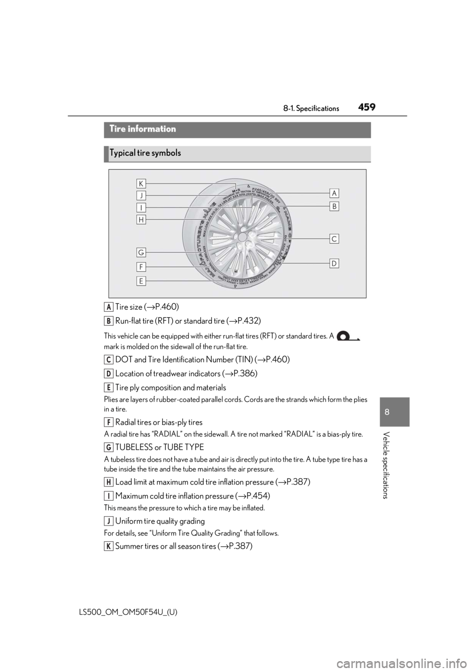
Tire size ( → P.460)
Run-flat tire (RFT) or standard tire ( → P.432)This vehicle can be equipped with either run-flat tires (RFT) or standard tires. A
mark is molded on the side wall of the run-flat tire.
DOT and Tire Identification Number (TIN) ( → P.460)
Location of treadwear indicators ( → P.386)
Tire ply composition and materialsPlies are layers of rubber-coa ted parallel cords. Cords are the strands which form the plies
in a tire.
Radial tires or bias-ply tiresA radial tire has “RADIAL” on the sidewall. A tire not marked “RADIAL” is a bias-ply tire.
TUBELESS or TUBE TYPEA tubeless tire does not have a tube and air is directly put into the tire. A tube type tire has a
tube inside the tire and the tube maintains the air pressure.
Load limit at maximum cold tire inflation pressure ( → P.387)
Maximum cold tire inflation pressure ( → P.454)This means the pressure to which a tire may be inflated.
Uniform tire quality gradingFor details, see “Uniform Tire Quality Grading” that follows.
Summer tires or all season tires ( → P.387)Tire information
Typical tire symbols
A
B
C
D
E
F
G
H
I
J
K
Page 462 of 514

460 8-1. Specifications
LS500_OM_OM50F54U_(U) An all season tire has “M+S” on the sidewall. A tire not marked “M+S” is a summer tire.
Type A
DOT symbol *
Tire Identification Number (TIN)
Tire manufacturer’s identification
mark
Tire size code
Manufacturer’s optional tire type
code (3 or 4 letters)
Manufacturing week
Manufacturing year *
:The DOT symbol cert ifies that the tire
conforms to applicable Federal Motor
Vehicle Safety Standards.
Type B
DOT symbol * Tire Identification Number (TIN)
Tire manufacturer’s identification
mark
Manufacturer’s code
Manufacturing week
Manufacturing year *
: The DOT symbol certifies that the tire
conforms to applicable Federal Motor
Vehicle Safety Standards.
■
Typical tire size information
The illustration indicates typical tire
size.
Tire use (P = Passenger car, T =
Temporary use)
Section width (millimeters)
Aspect ratio (tire height to section
width)
Tire construction code (R = Radial,
D = Diagonal)
Run-flat tire code
Wheel diameter (inches)
Load index (2 digits or 3 digits)
Speed symbol (alphabet with one Typical DOT and Tire Identifica-
tion Number (TIN)
A
B
C
D
E
F
G
A Tire size B
C
D
E
F
A
B
C
D
E
F
G
H
Page 468 of 514

466 8-1. Specifications
LS500_OM_OM50F54U_(U) Pneumatic tire A mechanical device made of rubber, chemicals,
fabric and steel or other materials, that, when
mounted on an automotive wheel, provides the
traction and contains the gas or fluid that sustains
the load
Radial ply tire A pneumatic tire in which the ply cords that extend
to the beads are laid at su bstantially 90 degrees to
the centerline of the tread
Reinforced tire A tire designed to operat e at higher loads and at
higher inflation pressures than the corresponding
standard tire
Section width The linear distance between the exteriors of the
sidewalls of an inflated tire, excluding elevations
due to labeling, decoration, or protective bands
Sidewall That portion of a tire between the tread and bead
Sidewall separation The parting of the rubber compound from the cord
material in the sidewall
Snow tire A tire that attains a traction index equal to or
greater than 110, compared to the ASTM E-1136
Standard Referenc e Test Tire, when using the snow
traction test as described in ASTM F-1805-00,
Standard Test Method fo r Single Wheel Driving
Traction in a Straight Li ne on Snow-and Ice-Cov-
ered Surfaces, and which is marked with an Alpine
Symbol ( ) on at least one sidewall
Test rim The rim on which a tire is fitted for testing, and may
be any rim listed as appropriate for use with that tire
Tread That portion of a tire that comes into contact with
the road
Tread rib A tread section running ci rcumferentially around a
tire
Tread separation Pulling away of the tread from the tire carcassTire related term Meaning