2018 KIA STINGER fuse panel
[x] Cancel search: fuse panelPage 14 of 551
Your vehicle at a glance
42
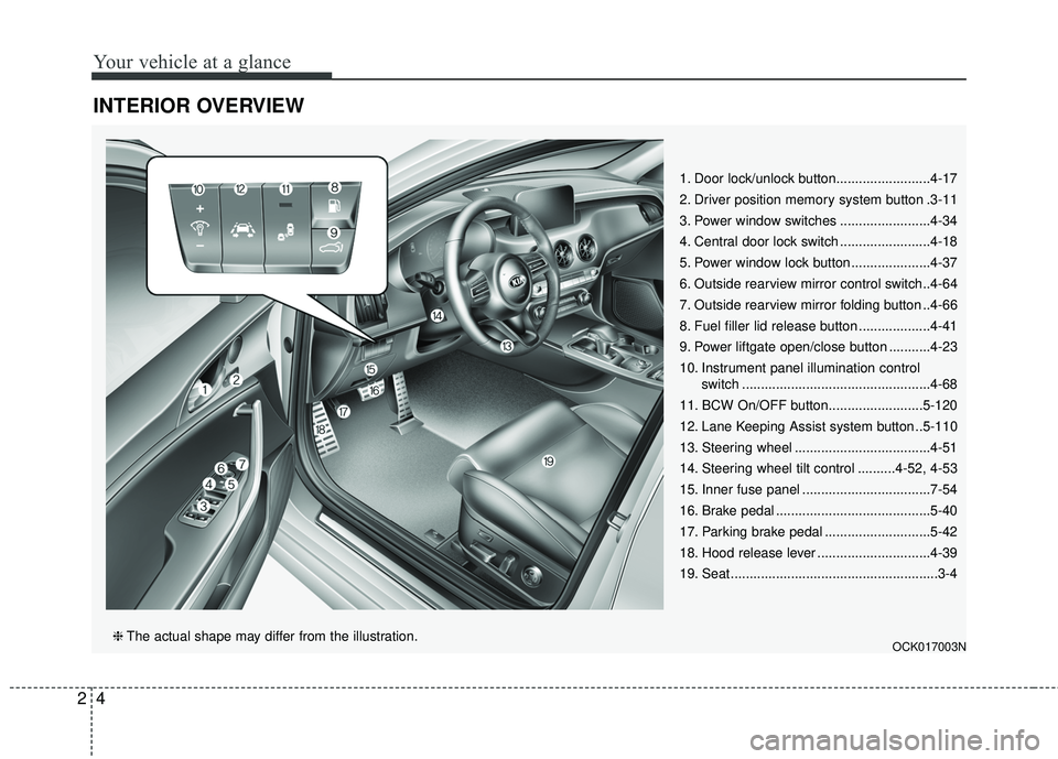
INTERIOR OVERVIEW
1. Door lock/unlock button.........................4-17
2. Driver position memory system button .3-11
3. Power window switches ........................4-34
4. Central door lock switch ........................4-18
5. Power window lock button .....................4-37
6. Outside rearview mirror control switch..4-64
7. Outside rearview mirror folding button ..4-66
8. Fuel filler lid release button ...................4-41
9. Power liftgate open/close button ...........4-23
10. Instrument panel illumination control switch ..................................................4-68
11. BCW On/OFF button.........................5-120
12. Lane Keeping Assist system button ..5-110
13. Steering wheel ....................................4-51
14. Steering wheel tilt control ..........4-52, 4-53
15. Inner fuse panel ..................................7-54
16. Brake pedal .........................................5-40
17. Parking brake pedal ............................5-42
18. Hood release lever ..............................4-39
19. Seat .......................................................3-4
OCK017003N❈ The actual shape may differ from the illustration.
Page 68 of 551

Safety features of your vehicle
52
3
The SRS can function only when
the Engine Start/Stop button is in
the ON position. If the SRS air bag
warning light does not illuminate,
or continuously remains on after
illuminating for about 6 seconds
when the ignition switch is turned
to the ON position, or after the
engine is started, comes on while
driving, the SRS is not working
properly. If this occurs, have your
vehicle immediately inspected by
an authorized Kia dealer.
✽ ✽ NOTICE
Before you replace a fuse or discon-
nect a battery terminal, turn the
Engine Start/Stop button to the OFF
position.
Never remove or replace the air bag
related fuse (s) when the Engine
Start/Stop button to the ON position.
Failure to heed this warning will
cause the SRS air bag warning light
to illuminate.
Occupant Detection System
(ODS)
Your vehicle is equipped with an
occupant detection system in the
front passenger's seat.
The occupant detection system is
designed to detect the presence of a
properly-seated front passenger and
determine if the passenger's front air
bag should be enabled (may inflate)
or not. Only the front passenger front
air bag is controlled by the Occupant
Detection System.
Do not put anything in front of the
passenger air bag indicator.
Main components of the occu-
pant detection system
An detection device located within the front passenger seat cushion.
An electronic system which deter- mines whether the passenger air
bag systems should be activated
or deactivated.
An indicator light located on the instrument panel which illuminates
the words PASSENGER AIR BAG
“OFF” indicates the front passen-
ger air bag system is deactivated.
The instrument panel air bag warn- ing light is interconnected with the
occupant detection system.
OCK037035
Page 430 of 551

• Radial-ply tires . . . . . . . . . . . . . . . . . . . . . . . . . . . . . . 7-51
• Low aspect ratio tire . . . . . . . . . . . . . . . . . . . . . . . . . . 7-52
Fuses . . . . . . . . . . . . . . . . . . . . . . . . . . . . . . . . . . . . \
7-54
• Inner panel fuse replacement . . . . . . . . . . . . . . . . . . . 7-56
• Engine compartment fuse replacement. . . . . . . . . . . 7-58
• Fuse/relay panel description. . . . . . . . . . . . . . . . . . . . 7-60
Light bulbs . . . . . . . . . . . . . . . . . . . . . . . . . . . . . . . 7-77
• Bulb replacement precaution . . . . . . . . . . . . . . . . . . . 7-77
• Light bulb position (Front) . . . . . . . . . . . . . . . . . . . . 7-78
• Light bulb position (Rear) . . . . . . . . . . . . . . . . . . . . . 7-79
• Light bulb position (Side) . . . . . . . . . . . . . . . . . . . . . . 7-79
• Headlamp (LED type) replacement(Headlamp Type B) . . . . . . . . . . . . . . . . . . . . . . . . . . 7-80
• Side marker bulb replacement (Headlamp Type A) . . . . . . . . . . . . . . . . . . . . . . . . . . 7-80
• Position lamp + DRL (LED type) bulb replacement (Headlamp Type A) . . . . . . . . . . . . . . . . . . . . . . . . . . 7-80
• Headlamp (Low/High beam) bulb replacement (Headlamp Type A) . . . . . . . . . . . . . . . . . . . . . . . . . . 7-81
• Front turn signal lamp bulb replacement (Headlamp Type A) . . . . . . . . . . . . . . . . . . . . . . . . . . 7-82
• Stop and tail lamp (LED type) bulb replacement . . 7-83
• Rear side marker (LED type) bulb replacement . . . 7-84
• Rear turn signal lamp (LED type) bulb replacement. . 7-84
• Rear turn signal lamp (bulb type) bulb replacement . . 7-84• Back-up lamp bulb replacement . . . . . . . . . . . . . . . . 7-86
• High mounted stop lamp (LED type) bulb
replacement . . . . . . . . . . . . . . . . . . . . . . . . . . . . . . . . 7-88
• License plate lamp (LED type) bulb replacement . . 7-88
• Side repeater lamp (LED type) bulb replacement . . 7-88
• Map lamp (LED type) bulb replacement . . . . . . . . . 7-89
• Vanity mirror lamp (LED type) bulb replacement . . 7-89
• Room lamp (LED type) bulb replacement . . . . . . . . 7-89
• Glove box lamp (LED type) bulb replacement . . . . 7-90
• Luggage room lamp (LED type) bulb replacement. . 7-90
Appearance care . . . . . . . . . . . . . . . . . . . . . . . . . . . 7-91
• Exterior care . . . . . . . . . . . . . . . . . . . . . . . . . . . . . . . . 7-91
• Interior care . . . . . . . . . . . . . . . . . . . . . . . . . . . . . . . . . 7-96
Emission control system . . . . . . . . . . . . . . . . . . . . 7-99
• Crankcase emission control system . . . . . . . . . . . . . . 7-99
• Evaporative emission control (including ORVR
Onboard Refueling Vapor Recovery) system . . . . . 7-99
• Exhaust emission control system . . . . . . . . . . . . . . . 7-100
7
Page 482 of 551

Maintenance
54
7
FUSES
❈ Left side : Normal , Right side : Blown
A vehicle’s electrical system is pro-
tected from electrical overload dam-
age by fuses.
This vehicle has 4 (or 5) fuse panels,
one located in the driver’s side panel
bolster, the other in the engine com-
partment near the battery.
If any of your vehicle’s lights, acces-
sories, or controls do not work, check
the appropriate circuit fuse. If a fuse
has blown, the element inside the
fuse will melt.
If the electrical system does not
work, first check the driver’s side
fuse panel.
Always replace a blown fuse with
one of the same rating.
If the replacement fuse blows, this
indicates an electrical problem. Avoid
using the system involved and imme-
diately consult an authorized Kia
dealer.
Three kinds of fuses are used: blade
type for lower amperage rating, car-tridge type, and multi fuse for higheramperage ratings.
Do not arbitrarily modify or add-on electric wiring to the vehicle.
WARNING- Fuse replace-
ment
Never replace a fuse with any- thing but another fuse of the
same rating.
A higher capacity fuse could cause damage and possibly a
fire.
Never install a wire or alu- minum foil instead of the
proper fuse - even as a tem-
porary repair. It may cause
extensive wiring damage and
a possible fire.
CAUTION
Do not use a screwdriver or anyother metal object to removefuses because it may cause ashort circuit and damage thesystem.
OCK077071
■
Blade type
■ Cartridge type
■ Multi fuse
■ Fusible link
Page 483 of 551

755
Maintenance
✽ ✽NOTICE
• When replacing fuse, turn the
ignition “OFF” and turn off
switches of all electrical devices
then remove battery (-) terminal.
• The actual fuse/relay panel label may differ from equipped items.
WARNING- Electrical Fire
Always ensure replacements
fuses and relays are securely
fastened when installed. Failure
to do so can result in a vehicle
fire.
CAUTION
When replacing a blown fuse or relay, make sure the newfuse or relay fits tightly intothe clips. Failure to tightlyinstall the fuse or relay maycause damage to the wiringand electric systems.
Do not remove fuses, relays and terminals fastened withbolts or nuts. The fuses, relaysand terminals may not be fas-tened correctly which maycause vehicle damage.
CAUTION
Do not input any other objects except fuses or relays intofuse/relay terminals such as adriver or wiring. It may causecontact failure and systemmalfunction.
Do not plug in screwdrivers or aftermarket wiring into the ter-minal originally designed forfuse and relays only. The elec-trical system and wiring of thevehicle interior may be dam-aged or burned due to contactfailure.
If you directly connect the wire on the taillight or replacethe bulb which is over the reg-ulated capacity to install trail-ers etc., the inner junctionblock can get burned.
Page 484 of 551
Maintenance
56
7
✽ ✽
NOTICE- Remodeling
Prohibited
Do not rewire your vehicle in any
way as doing so may affect the per-
formance of several safety features
in your vehicle. Rewiring your vehi-
cle may also void your warranty and
cause you to be responsible for any
subsequent vehicle damage which
may result.
✽ ✽ NOTICE- Window tinting
precaution
Window tint(especially metallic
film) might cause communication
disorder or poor radio reception,
and malfunction of the automatic
lighting system due to excessive
change of illumination inside the
vehicle. The solution used might also
flow into electric, electronic devices
causing disorder and failure.
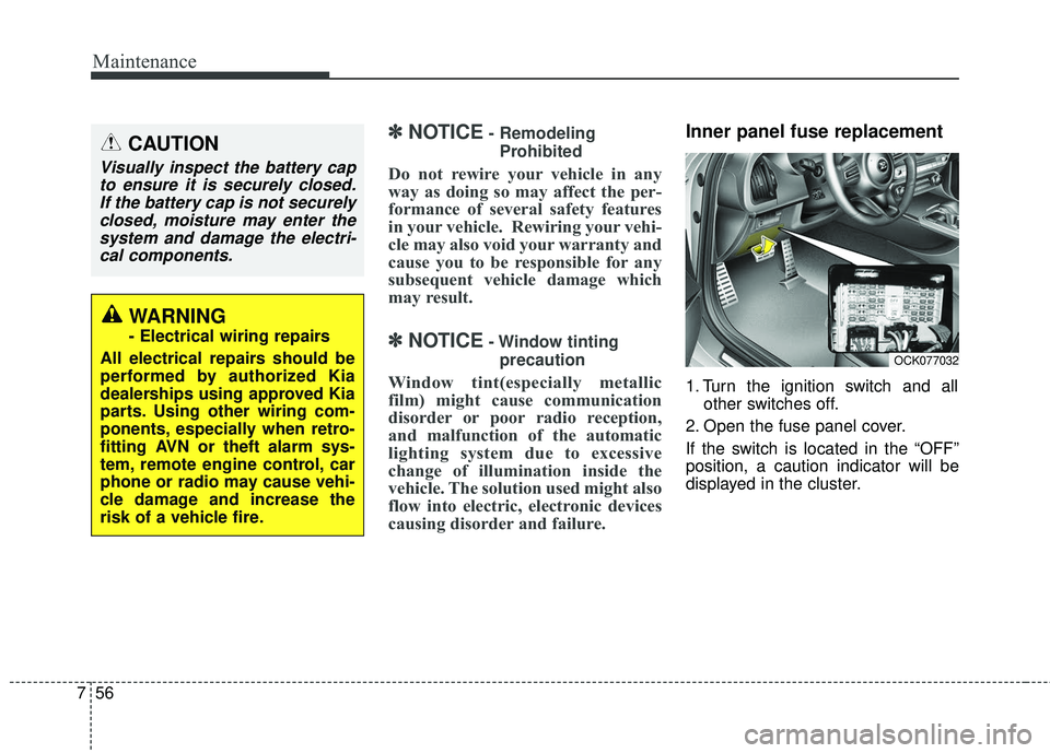
Inner panel fuse replacement
1. Turn the ignition switch and all other switches off.
2. Open the fuse panel cover.
If the switch is located in the “OFF”
position, a caution indicator will be
displayed in the cluster.
CAUTION
Visually inspect the battery cap to ensure it is securely closed.If the battery cap is not securelyclosed, moisture may enter thesystem and damage the electri-cal components.
WARNING
- Electrical wiring repairs
All electrical repairs should be
performed by authorized Kia
dealerships using approved Kia
parts. Using other wiring com-
ponents, especially when retro-
fitting AVN or theft alarm sys-
tem, remote engine control, car
phone or radio may cause vehi-
cle damage and increase the
risk of a vehicle fire.
OCK077032
Page 485 of 551

757
Maintenance
3. Pull the suspected fuse straightout. Use the removal tool provided
on the engine compartment fuse
panel cover.
4. Check the removed fuse; replace it if it is blown.
Spare fuses are provided in theengine compartment fuse panel.
5. Push in a new fuse of the same rating, and make sure it fits tightly
in the clips.
If it fits loosely, consult an authorized
Kia dealer.
If you do not have a spare, use a fuse of the same rating from a circuityou may not need for operating thevehicle, such as the power outletfuse.
If the head lamp, turn signal lamp,
stop signal lamp, fog lamp, DRL, tail
lamp, HMSL do not work and the
fuses are OK, check the fuse panel
in the engine compartment. If a fuse
is blown, it must be replaced.
✽ ✽ NOTICE
If the headlamp, fog lamp, turn sig-
nal lamp, or tail lamp malfunction
even without any problem to the
lamps, have the vehicle checked by
an authorized Kia dealer for assis-
tance.
Fuse switch
Always set the fuse switch to the ON
position before using the vehicle.
If you move the switch to the OFF
position, some items such as audio
and digital clock must be reset and
transmitter (or smart key) may not
work properly. When the switch is
Off, the caution indicator will be dis-
played on the instrument cluster.
Always place the fuse switch in the
ON position while driving the vehicle.
If the switch is located in the “OFF”
position, a caution indicator will be
displayed in the cluster.
OCK077033
OCK077034
Page 486 of 551
Maintenance
58
7
✽ ✽
NOTICE
• Set all switches to ON before driv-
ing.
• If the vehicle is going to be unused for over 1 month, set all switches
to OFF to prevent the batteries
from draining.
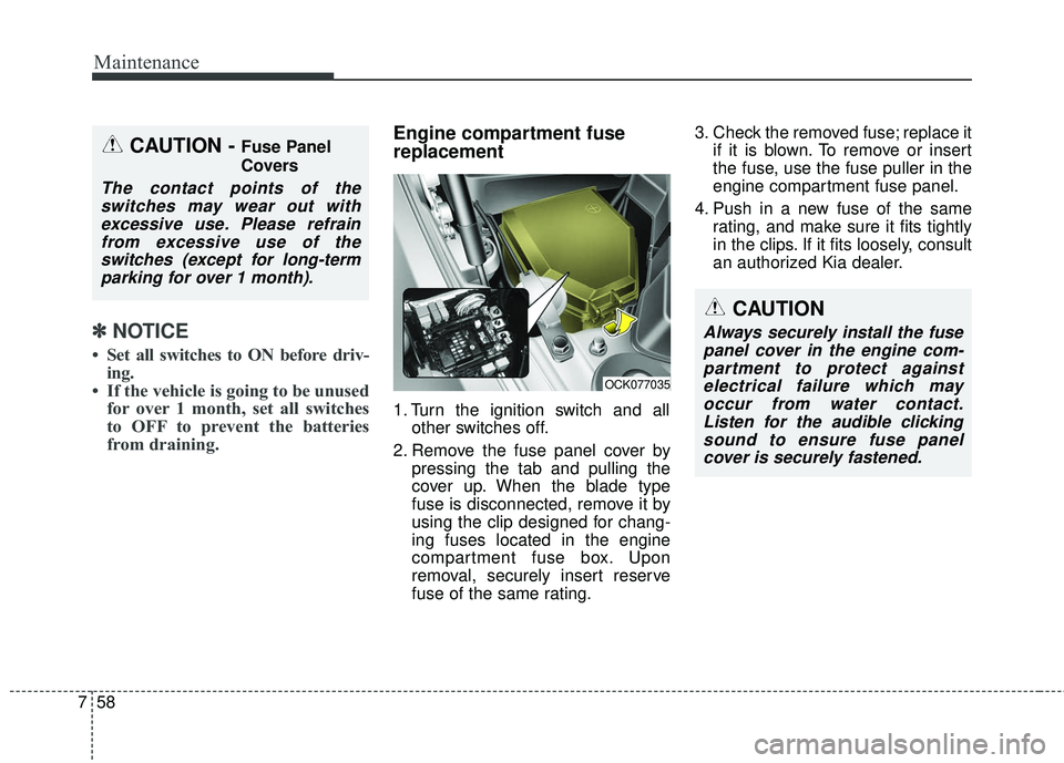
Engine compartment fuse
replacement
1. Turn the ignition switch and all
other switches off.
2. Remove the fuse panel cover by pressing the tab and pulling the
cover up. When the blade type
fuse is disconnected, remove it by
using the clip designed for chang-
ing fuses located in the engine
compartment fuse box. Upon
removal, securely insert reserve
fuse of the same rating. 3. Check the removed fuse; replace it
if it is blown. To remove or insert
the fuse, use the fuse puller in the
engine compartment fuse panel.
4. Push in a new fuse of the same rating, and make sure it fits tightly
in the clips. If it fits loosely, consult
an authorized Kia dealer.
CAUTION
Always securely install the fusepanel cover in the engine com-partment to protect againstelectrical failure which mayoccur from water contact.Listen for the audible clickingsound to ensure fuse panelcover is securely fastened.
CAUTION - Fuse Panel
Covers
The contact points of theswitches may wear out withexcessive use. Please refrainfrom excessive use of theswitches (except for long-termparking for over 1 month).
OCK077035