2018 KIA CARENS RHD instrument panel
[x] Cancel search: instrument panelPage 234 of 723

Features of your vehicle
138
4
✽✽
NOTICE
If you want to defrost and defog the
front windscreen, refer to
“Windscreen Defrosting and
Defogging” in this chapter.
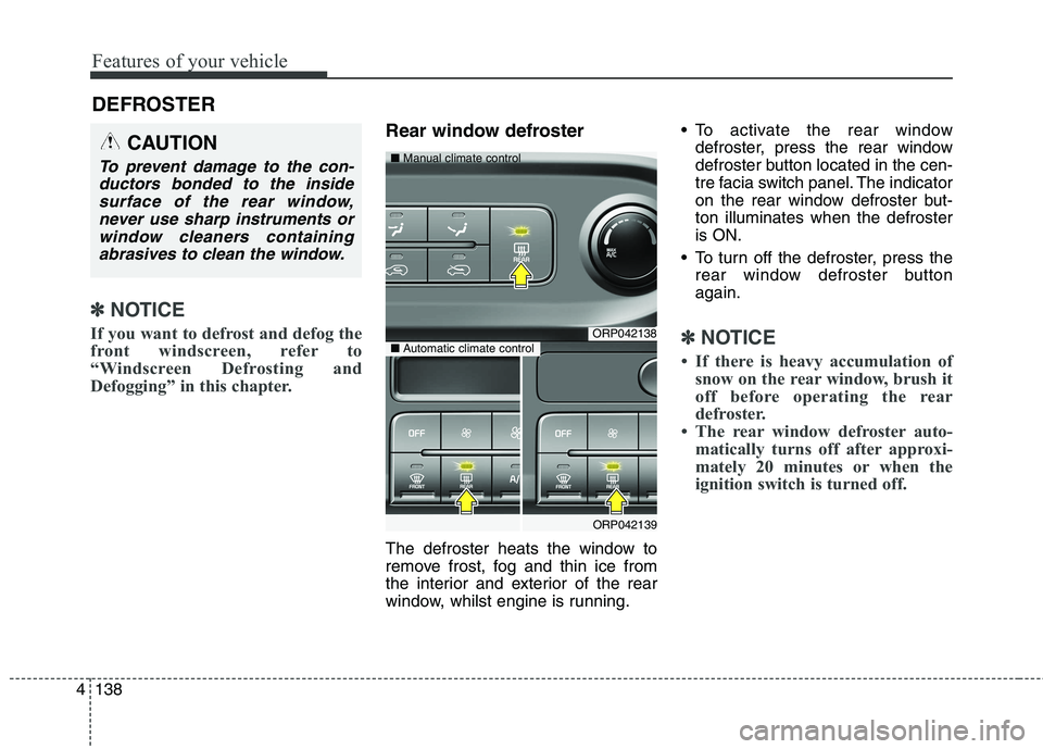
Rear window defroster
The defroster heats the window to
remove frost, fog and thin ice from
the interior and exterior of the rear
window, whilst engine is running. To activate the rear window
defroster, press the rear window
defroster button located in the cen-
tre facia switch panel. The indicator
on the rear window defroster but-ton illuminates when the defrosteris ON.
To turn off the defroster, press the rear window defroster buttonagain.
✽✽ NOTICE
If there is heavy accumulation of snow on the rear window, brush it
off before operating the rear
defroster.
The rear window defroster auto- matically turns off after approxi-
mately 20 minutes or when the
ignition switch is turned off.
DEFROSTER
CAUTION
To prevent damage to the con-
ductors bonded to the insidesurface of the rear window, never use sharp instruments orwindow cleaners containingabrasives to clean the window.
ORP042138
ORP042139
■
Manual climate control
■Automatic climate control
Page 239 of 723

4143
Features of your vehicle
Instrument panel vents
The outlet vents can be opened or
closed separately using the thumb-
wheel or vent control lever.
Also, you can adjust the direction of
air delivery from these vents using
the vent control lever as shown.
Temperature control
The temperature control knob allows
you to control the temperature of the
airflow in the vehicle.
To change the temperature:
Turn the knob to the right toincrease temperature.
Turn the knob to the left to decrease temperature.
Air intake control
The air intake control is used to select the outside (fresh) air positionor recirculated air position.
To change the air intake control posi-
tion, press the control button.
ORP042144ORP042145
ORP042143R
Page 248 of 723

Features of your vehicle
152
4
2. Turn the temperature control knob
to set the desired temperature.
✽✽ NOTICE
To turn the automatic operation off, select any button of the following:- Mode selection button
- Air conditioning button (Except Europe)
- Front windscreen defrost button (Press the button one more time
to deselect the front windscreen
defroster function. The ‘AUTO’
sign will illuminate on the infor-
mation display once again.)
- Fan speed control button
The selected function will be con-
trolled manually whilst other
functions operate automatically.
For your convenience and to improve the effectiveness of the
climate control, use the AUTO
button and set the temperature to
22°C/71°F (23°C/73°F -Except
Europe). ✽
✽
NOTICE
Placing any object over the sensor
on the instrument panel may inter-
fere with the heating and cooling
system.
ORP046151RORP042150
Page 250 of 723

Features of your vehicle
154
4
Face-Level (B, D, F*)
Air flow is directed toward the upper
body and face. Additionally, eachoutlet can be controlled to direct theair discharged from the outlet.
* : if equipped Floor-Level (A, C, D, E)
Most of the air flow is directed to the
floor.
Defrost-Level (A, D)
Most of the air flow is directed to thewindscreen.
Also you may select 2~3 modes at
the same time.
- face ( ) + floor ( ) mode
- face ( ) + defrost ( ) mode
- floor ( ) + defrost ( ) mode
- face ( ) + floor ( ) + defrost ( ) mode Instrument panel vents
The outlet vents can be opened or
closed separately using the thumb-
wheel or vent control lever.
Also, you can adjust the direction of
air delivery from these vents using
the vent control lever as shown.
ORP042143RORP046152L
Page 512 of 723

677
Driving your vehicle
DRIVER'S ATTENTION
The driver must be cautious in the
below situations for the system may
not assist the driver and may not
work properly.
Do not stick or attach anything tothe windscreen in front of the cam-
era as this may reduce effective-ness or cause one more of the sys-
tems dependent on the camera to
stop working.
Keep the windscreen in the area behind the interior rear view mirrorclean.
Do not place reflective materials, such as white paper or a mirror, on
the instrument panel.
Do not strike or damage the areas around the camera unit.
Do not touch the camera lens or remove the screw located on the
camera unit. The system does not work in all sit-
uations but is designed merely as a
supplementary aid.
The system assists the driver and does not replace the human eye.
The driver always bears ultimate responsibility for ensuring that the
vehicle is driven safely and that
applicable road traffic rules and
regulations are followed.
Page 539 of 723

Driving your vehicle
104
6
Backing up
Hold the bottom of the steering
wheel with one hand. Then, to move
the trailer to the left, just move your
hand to the left. To move the trailer to
the right, move your hand to the
right. Always back up slowly and, if
possible, have someone guide you.
Making turns
When you’re turning with a trailer,
make wider turns than normal. Do
this so your trailer won’t strike soft
shoulders, kerbs, road signs, trees,
or other objects. Avoid jerky or sud-
den manoeuvres. Signal well in
advance.
Turn signals when towing a trailer
When you tow a trailer, your vehicle
has to have a different turn signal
flasher and extra wiring. The green
arrows on your instrument panel will
flash whenever you signal a turn or
lane change. Properly connected,
the trailer lights will also flash to alert
other drivers you’re about to turn,
change lanes, or stop.
When towing a trailer, the green
arrows on your instrument panel will
flash for turns even if the bulbs on the
trailer are burned out. Thus, you may
think drivers behind you are seeing
your signals when, in fact, they are
not. It is important to check occasion-
ally to be sure the trailer bulbs are still
working. You must also check the
lights every time you disconnect and
then reconnect the wires.
Do not connect a trailer lighting sys-
tem directly to your vehicle’s lighting
system. Use only an approved trailer
wiring harness. Have yourself assist-
ed by a professional workshop in
installing the wiring harness. Kia recommends to visit an autho-
rised Kia dealer/service partner.WARNING
Failure to use an approved trail- er wiring harness could result
in damage to the vehicle electri-
cal system and/or personal
injury.
Page 657 of 723

Maintenance
70
8
Instrument panel (Driver’s side fuse panel)
No.Fuse ratingSymbolFuse NameProtected component
130ADRVP/SEAT DRV4WAY : Driver Lumbar Support Switch
6WAY : Driver Seat Manual Switch
225ARHP/WDW RHPower Window Relay RH, Driver/Passenger Safety Power Window Module,
Rear Safety Power Window Module RH
325ALHP/WDW LHPower Window Relay LH, Driver/Passenger Safety Power
Window Module, Rear Safety Power Window Module LH
420ADR LOCKDoor Lock/Unlock Relay, Dead Lock Relay
515ASPARE 1-
620APOWER
OUTLET1POWER
OUTLET 1Cigarette Lighter, Rear Power Outlet
720ASPARE 3-
87.5AMODULE3MODULE 3Frt Seat Warmer Sw, Hlld Sw, Navigation, Amp, Rear Seat Warmer Ecu,
Auto Hlld Ecu, Heater Control Unit
920AFRTS/HEATER FRT SEAT VENTDriver/Passenger Seat Warmer Module
1010AMODULE6MODULE 6A/V & Navigation Head Unit (W/O ISG), Audio (W/O ISG), DC-DC Converter (With ISG),
Digital Clock, Smart Key Control Module, BCM, Outside Mirror Switch, Outside Mirror
Page 717 of 723

I5
Index
Exterior features ..........................................................4-186
Roof rack ..................................................................4-186
Exterior overview ............................................................2-2
Fuel filler lid ..................................................................4-41 Closing the fuel filler lid ............................................4-41
Opening the fuel filler lid ..........................................4-41
Fuel Filter ......................................................................8-40 Draining water from fuel filter ..................................8-40
Fuel requirements ............................................................1-3 Diesel engine ................................................................1-6
Petrol engine ................................................................1-3
Fuses ..............................................................................8-63 Fuse/relay panel description ......................................8-69
Gross vehicle weight........................................................9-3
How to use this manual ..................................................1-2
If the engine does not start ..............................................7-4 If engine doesn't turn over or turns over slowly ..........7-4
If engine turns over normally but does not start ..........7-4
If the engine overheats ....................................................7-8
If you have a flat tyre (with spare tyre) ........................7-15 Changing tyres ..........................................................7-17
EC Declaration of Conformity for Jack......................7-25
Jack and tools ..............................................................7-15
Jack label ....................................................................7-24
Removing and storing the spare tyre ..........................7-16
If you have a flat tyre (with tyre mobility kit) ..............7-26 Checking the tyre inflation pressure ..........................7-30
Components of the Tyre Mobility Kit (TMK) ............7-27
Distributing the sealant ..............................................7-30
Introduction ................................................................7-26
Notes on the safe use of the Tyre Mobility Kit ..........7-31
Technical Data ............................................................7-31
Using the Tyre Mobility Kit (TMK) ..........................7-28
In case of an emergency whilst driving ..........................7-3 If engine stalls whilst driving ......................................7-3
If the engine stalls at a crossroad or crossing ..............7-3
If you have a flat tyre whilst driving ............................7-3
Instrument cluster ..........................................................4-57 Gauges ........................................................................4-60
Instrument Cluster Control ........................................4-58
LCD Display Control ..................................................4-59
Transaxle Shift Indicator ............................................4-64
Instrument panel overview ..............................................2-5
Interior features............................................................4-172
F
H
G
I