Page 41 of 312

IconDescription
Front Defrost Button
Press and release the touchscreen button, or push and release the button on the faceplate, to change the current airflow
setting to Defrost mode. The indicator illuminates when this feature is on. Air comes from the windshield and side win-
dow demist outlets. When the defrost button is selected, the blower level may increase. Use Defrost mode with maxi-
mum temperature settings for best windshield and side window defrosting and defogging. When toggling the front de-
frost mode button, the climate system will return to the previous setting.
Rear Defrost Button
Push and release the button on the touchscreen, or push and release the button on the faceplate, to turn on the rear
window defroster and the heated outside mirrors (if equipped). An indicator will illuminate when the rear window de-
froster is on. The rear window defroster automatically turns off after ten minutes.
Uconnect 3
Uconnect 3C/3C NAV
Driver and Passenger Temperature Up and Down Buttons
Provides the driver and passenger with independent temperature control. Push the red button on the faceplate or touch-
screen or press and slide the temperature bar towards the red arrow button on the touchscreen for warmer temperature
settings. Push the blue button on the faceplate or touchscreen or press and slide the temperature bar towards the blue
arrow button on the touchscreen for cooler temperature settings.
NOTE:
The numbers within the temperature display will only appear if the system is equipped with an automatic climate con-
trol system.
39
Page 55 of 312
GETTING TO KNOW YOUR INSTRUMENT PANEL
INSTRUMENT CLUSTER
DISPLAY...................54
Instrument Cluster Display Controls ....54
Oil Change Reset — If Equipped ......55
Instrument Cluster Display Selectable
Items ......................55
WARNING LIGHTS AND
MESSAGES.................56
Red Warning Lights ..............56
Yellow Warning Lights ............59
Yellow Indicator Lights ............63
Green Indicator Lights ............63 White Indicator Lights
............64
Blue Indicator Lights .............65ONBOARD DIAGNOSTIC
SYSTEM—OBDII ............66
Onboard Diagnostic System (OBD II)
Cybersecurity.................66
GETTING TO KNOW YOUR INSTRUMENT PANEL
53
Page 67 of 312

— Selec Speed Control Indicator
Light — If Equipped
This light will turn on when “Selec Speed
Control” is activated.
To activate “Selec Speed Control”, assure the
vehicle is Four Wheel Drive Low (4WD) and
push the button on the Instrument Panel.
NOTE:
If the vehicle is not in 4WD Low, “To Enter
Selec-Speed Shift to 4WD Low” will appear
in the instrument cluster display.
— Cruise Control Ready Indicator
Light
This light will turn on when the speed control
has been turned on, but not set. Refer to
“Speed Control — If Equipped” in “Starting
And Operating” for further information.
— Hill Descent Control (HDC) Indicator
Light — If Equipped
This indicator shows when the Hill Descent
Control (HDC) feature is turned on. The lamp
will be on solid when HDC is armed. HDC can only be armed when the transfer case is in the
“4WD LOW” position and the vehicle speed
is less then 30 mph (48 km/h). If these
conditions are not met while attempting to
use the HDC feature, the HDC indicator light
will flash on/off.
— LaneSense Indicator Light —
If Equipped
When the LaneSense system is ON, but not
armed, the LaneSense indicator is solid
white. This occurs when only left, right, or
neither lane line has been detected. If a
single lane line is detected, the system is
ready to provide only visual warnings if an
unintentional lane departure occurs on the
detected lane line.
Refer to “LaneSense — If Equipped" in
“Starting And Operating” for further informa-
tion.
— Passive Speed Limiter Engaged
The indication light up white along with a
notification text message (speed warning set
to xx followed by unit). When the set speed is just exceeded, a single chime will sound
along with pop up message of speed warning
exceeded. When the set speed is exceeded by
2 mph (3 km/h) or more, the indication will
light up yellow and flash along with a continu-
ous chime (up to 10 seconds or until the
speed is no longer exceeded).
NOTE:
The number “31” is only an example of a
speed that can be select.
Blue Indicator Lights
— High Beam Indicator Light
This indicator shows that the high beam
headlights are on. With the low beams acti-
vated, push the multifunction lever forward
(toward the front of the vehicle) to turn on the
high beams. Pull the multifunction lever rear-
ward (toward the rear of the vehicle) to turn
off the high beams. If the high beams are off,
pull the lever toward you for a temporary high
beam on, "flash to pass" scenario.
65
Page 163 of 312

Exterior Bulbs
Bulb Number
Low Beam/High Beam (Bi-Halogen) Headlamps 9005HL + Low Beam/High Beam (Bi-Xenon) Headlamps D3S (Serviced at an authorized dealer) Front Park/Daytime Running Lamps LED (Serviced at an authorized dealer)
Front Turn Signal Lamps WY21WFront Fog Lamps PSX24W
Rear Tail/Stop Lamps LED (Serviced at an authorized dealer)
Rear Turn Signal Lamps WY21W
Center High Mounted Stop Lamp (CHMSL) LED (Serviced at an authorized dealer) Back-Up Lamps W16W or 921
License Plate Lamp W5W Rear Fog Lamps W21W
Replacing Exterior Bulbs
Bi-Xenon High Intensity Discharge (HID)
Headlamps — If Equipped
The headlamps contain a type of high voltage
discharge light source. High voltage can re-
main in the circuit even with the headlamp
switch off. Because of this, you should not
attempt to service a HID headlamp light source yourself. If an HID headlamp light
source fails, take your vehicle to an autho-
rized dealer for service.
NOTE:
On vehicles equipped with HID headlamps,
when the headlamps are turned on, there is a
blue hue to the lights. This diminishes and
becomes more white after approximately
10 seconds, as the system charges.
WARNING!
A transient high voltage occurs at the bulb
sockets of HID headlamps when the head-
lamp switch is turned ON. It may cause
serious electrical shock or electrocution if
not serviced properly. See your authorized
dealer for service.
161
Page 167 of 312
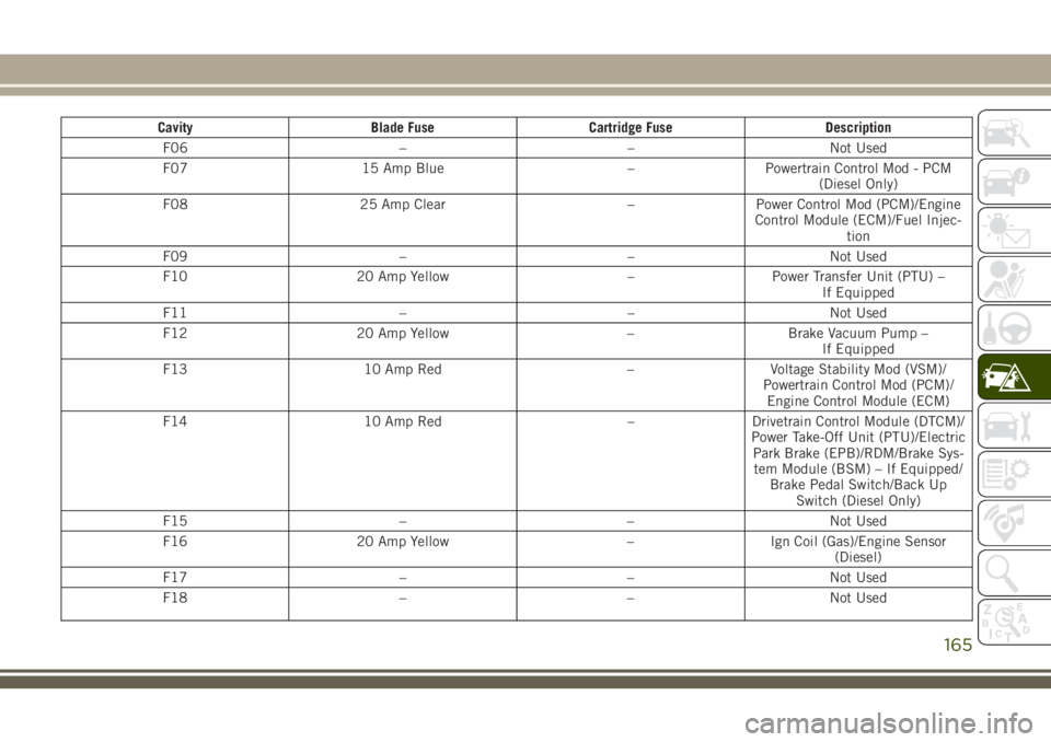
CavityBlade Fuse Cartridge Fuse Description
F06 ––Not Used
F07 15 Amp Blue –Powertrain Control Mod - PCM
(Diesel Only)
F08 25 Amp Clear –Power Control Mod (PCM)/Engine
Control Module (ECM)/Fuel Injec- tion
F09 ––Not Used
F10 20 Amp Yellow –Power Transfer Unit (PTU) –
If Equipped
F11 ––Not Used
F12 20 Amp Yellow –Brake Vacuum Pump –
If Equipped
F13 10 Amp Red –Voltage Stability Mod (VSM)/
Powertrain Control Mod (PCM)/ Engine Control Module (ECM)
F14 10 Amp Red –Drivetrain Control Module (DTCM)/
Power Take-Off Unit (PTU)/Electric Park Brake (EPB)/RDM/Brake Sys-tem Module (BSM) – If Equipped/ Brake Pedal Switch/Back Up Switch (Diesel Only)
F15 ––Not Used
F16 20 Amp Yellow –Ign Coil (Gas)/Engine Sensor
(Diesel)
F17 ––Not Used
F18 ––Not Used
165
Page 168 of 312
CavityBlade Fuse Cartridge Fuse Description
F19 –40 Amp Green Starter Solenoid
F20 10 Amp Red –A/C Compressor Clutch
F21 ––Not Used
F22 5 Amp Tan –Radiator Fan
F23 70 Amp Tan –Body Controller Module (BCM) –
Feed 2
F23 50 Amp Red –Voltage Stability Module (VSM)
Feed #2 – If Equipped With Stop/ Start Engine Option
F24 20 Amp Yellow –Rear Wiper – If Equipped With
Stop/Start Engine Option
F25B 20 Amp Yellow –Front Washer – If Equipped With
Stop/Start Engine Option
F26 –30 Amp PinkFuel Heater – Diesel Only
F27 ––Not Used
F28 15 Amp Blue –Transmission Control Module
(TCM)
F29 ––Not Used
F30 10 Amp Red –Engine Control Module (ECM)/
(EPS)/Fuel Pump Relay Feed/ (PCM)
F31 ––Not Used
F32 ––Not Used
F33 ––Not Used
F34 ––Not Used
IN CASE OF EMERGENCY
166
Page 169 of 312
CavityBlade Fuse Cartridge Fuse Description
F35 ––Not Used
F36 ––Not Used
F37 ––Not Used
F38 –60 Amp Yellow Glow Plugs (Diesel Only) –
If Equipped
F39 –40 Amp Green HVAC Blower Motor
F40 –20 Amp Blue Trailer Tow Park Light –
If Equipped
F40 –30 Amp PinkHeadlamp Washer Pump –
If Equipped
F41 –60 Amp YellowBody Controller Module (BCM) –
Feed 1
F41 –50 Amp RedVoltage Stability Module - Feed 1
– If Equipped With Stop/Start Engine Option
F42 –30 Amp PinkTrailer Tow Electric Brake Module
– If Equipped
F43 20 Amp Yellow –Fuel Pump Motor
F44 –30 Amp PinkTrailer Tow / 7-Way Connector –
If Equipped
F45 –30 Amp PinkPassenger Door Module (PDM) –
If Equipped
F46 –25 Amp Clear Sunroof – If Equipped
F48 –30 Amp PinkDriver Door Module – If Equipped
167
Page 170 of 312
CavityBlade Fuse Cartridge Fuse Description
F49 –30 Amp PinkPower Inverter (115V A/C) —
If Equipped
F50 –30 Amp PinkPower Liftgate – If Equipped
F51 ––Not Used
F52 –30 Amp PinkFront Wipers – If Equipped With
Stop/Start Engine Option
F53 –30 Amp PinkBrake System Module & Valves
F54 –30 Amp PinkBody Control Module (BCM)
Feed 3
F55 10 Amp Red –Blind Spot Sensors/Rearview
Camera
F56 15 Amp Blue –Ignition Node Module (IGNM)/
KIN/RF Hub/Electric Steering Column Lock (ESCL)
F57 20 Amp Yellow –Trailer Tow Lights Left –
If Equipped
F58 10 Amp Red –Occupant Classification Module/
VSM/TT Mod/ESCL
F59 –30 Amp PinkDrivetrain Control Module (DTCM)
– If Equipped
F60 20 Amp Yellow –Power Outlet – Center Console
F61 20 Amp Yellow –Trailer Tow Lights Right –
If Equipped
F62 20 Amp Yellow –Windshield De-Icer – If Equipped
IN CASE OF EMERGENCY
168