2018 JEEP CHEROKEE door lock
[x] Cancel search: door lockPage 127 of 312

WARNING!
• Never use the PARK position as a sub-stitute for the parking brake. Always ap-
ply the parking brake fully when exiting
the vehicle to guard against vehicle
movement and possible injury or dam-
age.
• When exiting the vehicle, always make
sure the ignition is in the OFF mode,
remove the key fob from the vehicle, and
lock your vehicle.
• Never leave children alone in a vehicle,
or with access to an unlocked vehicle.
Allowing children to be in a vehicle un-
attended is dangerous for a number of
reasons. A child or others could be seri-
ously or fatally injured. Children should
be warned not to touch the parking
brake, brake pedal or the transmission
gear selector.
• Do not leave the key fob in or near the
vehicle, (or in a location accessible to
children), and do not leave the ignition
in the ACC or ON/RUN mode. A child
WARNING!
could operate power windows, other con-
trols, or move the vehicle.
• Be sure the parking brake is fully disen-
gaged before driving; failure to do so can
lead to brake failure and a collision.
• Always fully apply the parking brake
when leaving your vehicle, or it may roll
and cause damage or injury. Also be
certain to leave the transmission in
PARK. Failure to do so may allow the
vehicle to roll and cause damage or in-
jury.
• Driving the vehicle with the parking
brake engaged, or repeated use of the
parking brake to slow the vehicle may
cause serious damage to the brake sys-
tem.
Auto Park Brake
The electric park brake can be programmed
to be applied automatically whenever the
vehicle is at a standstill and the automatic
transmission is placed in PARK, or with a
manual transmission, whenever the ignition
is turned “OFF”. Auto Park Brake is enabled and disabled by customer selection through
the customer programmable features section
of the Uconnect Settings.
Any single auto park brake application can be
bypassed by pushing the EPB switch to the
release position while the transmission is
placed in PARK.
SafeHold
SafeHold is a safety feature of the Electric
Park Brake System that will engage the park
brake automatically if the vehicle is left un-
secured while the ignition is in ON/RUN.
For automatic transmissions, the park brake
will automatically engage if all of the follow-
ing conditions are met:
• The vehicle is at a standstill.
• There is no attempt to depress the brake
pedal or accelerator pedal.
• The seat belt is unbuckled.
• The driver door is open.
125
Page 164 of 312

Bi-Halogen Headlamps
1. Remove the three hex head screws fromthe wheel liner.
2. Pull the exterior edge of the liner towards the tire to gain access to the headlamp
bulb cap.
3. Firmly grasp the cap and rotate it counter- clockwise to unlock it.
4. Firmly grasp the bulb and connector as- sembly and rotate counterclockwise to
remove from the housing.
5. Disconnect the bulb from the electrical connector and then connect the replace-
ment bulb.
CAUTION!
Do not touch the new bulb with your fin-
gers. Oil contamination will severely
shorten bulb life. If the bulb comes in
contact with any oily surface, clean the
bulb with rubbing alcohol.
6. Install the bulb and connector assembly into the headlamp housing and rotate
clockwise to lock it in place. 7. Install the bulb cap in the headlamp
housing and rotate clockwise to lock it in
place.
8. Install the three hex head screws into the wheel liner.
Front Turn Signals And Front Side Marker
Lamps
1. Open the hood.
NOTE:
Removal of the air cleaner filter housing
may be necessary prior to replacing bulbs
in the upper lamp assembly on the pas-
senger side of the vehicle.
2. Twist the appropriate bulb and socket assembly counterclockwise, and then re-
move the bulb and socket assembly from
the lamp housing.
3. Pull the bulb out of the socket and insert the replacement bulb.
4. Install the bulb and socket assembly into the housing, and rotate the socket clock-
wise to lock it in place.
5. Re-install air cleaner filter housing if removed.
Front Fog Lamp
1. Remove the three hex head screws from
the wheel liner.
2. Pull the exterior edge of the wheel liner towards the tire to gain access to the bulb.
3. Squeeze the two tabs on the side of the bulb socket and pull straight out from the
fog lamp.
4. Disconnect the wire harness from the bulb.
CAUTION!
Do not touch the new bulb with your fin-
gers. Oil contamination will severely
shorten bulb life. If the bulb comes in
contact with any oily surface, clean the
bulb with rubbing alcohol.
5. Reconnect the wiring harness to the new bulb and reinstall by inserting the new
bulb straight into the fog lamp housing
until it locks in place.
6. Lock the lower door in the wheel liner.
IN CASE OF EMERGENCY
162
Page 174 of 312

Interior Fuses
The interior fuse panel is located on the Body
Control Module (BCM) in the passenger com-
partment on the left side dash panel under
the instrument panel.
CavityBlade Fuse Description
F13 15 Amp Blue Low Beam Left
F32 10 Amp Red Interior Lighting
F36 10 Amp Red Intrusion Module/Siren – If Equipped
F38 20 Amp Yellow Deadbolt All Unlock
F43 20 Amp Yellow Washer Pump Front
F48 25 Amp Clear Fog Lamp Rear Left/Right – If Equipped
F49 7.5 Amp Brown Lumbar Support
F50 7.5 Amp Brown Wireless Charging Pad – If Equipped
F51 10 Amp Red Driver Window Switch/Power Mirrors – If Equipped
F53 7.5 Amp Brown UCI Port (USB & AUX)
F89 10 Amp Red Door Locks – Driver Unlock
F91 7.5 Amp Brown Left Front Fog Lamp (Low And High Line)
F92 7.5 Amp Brown Right Front Fog Lamp (High Line)
F93 10 Amp Red Low Beam Right
IN CASE OF EMERGENCY
172
Page 187 of 312

(E) After Driving:
Pull over to a safe location. Refer to “When-
ever You Stop To Use Tire Service Kit” before
continuing.
1. Push in the Mode Select Knob (5) andturn to the Air Mode position.
2. Uncoil the power plug and insert the plug into the vehicle's 12 Volt power outlet.
3. Uncoil the Air Pump Hose (7) (black in color) and screw the fitting at the end of
hose (7) onto the valve stem.
4. Check the pressure in the tire by reading the Pressure Gauge (3).
If tire pressure is less than 19 psi (1.3 Bar):
The tire is too badly damaged. Do not attempt
to drive the vehicle further. Call for assis-
tance.
If the tire pressure is 19 psi (1.3 Bar) or higher:
1. Push the Power Button (4) to turn on Tire Service Kit and inflate the tire to the
pressure indicated on the tire and loading
information label on the driver-side door
opening. NOTE:
If the tire becomes over-inflated, push the
Deflation Button to reduce the tire pres-
sure to the recommended inflation pres-
sure before continuing.
2. Disconnect the Tire Service Kit from the valve stem, reinstall the cap on the valve
stem and unplug from 12 Volt outlet.
3. Place the Tire Service Kit in its proper storage area in the vehicle.
4. Have the tire inspected and repaired or replaced at the earliest opportunity at an
authorized dealer or tire service center.
5. Remove the Speed Limit sticker from the instrument panel after the tire has been
repaired.
6. Replace the Sealant Bottle (1) and Seal- ant Hose (6) assembly at an authorized
dealer as soon as possible. Refer to “(F)
Sealant Bottle And Hose Replacement”.
NOTE:
When having the tire serviced, advise the
authorized dealer or service center that the
tire has been sealed using the Tire Service
Kit.
(F) Sealant Bottle And Hose Replacement:
1. Uncoil the Sealant Hose (6) (clear in color).
2. Locate the round Sealant Bottle release button in the recessed area under the
sealant bottle.
3. Push the Sealant Bottle release button. The Sealant Bottle (1) will pop up. Re-
move the bottle and dispose of it
accordingly.
4. Clean any remaining sealant from the Tire Service Kit housing.
5. Position the new Sealant Bottle (1) in the housing so that the Sealant Hose (6)
aligns with the hose slot in the front of the
housing. Push the bottle into the housing.
An audible click will be heard indicating
the bottle is locked into place.
6. Verify that the cap is installed on the fitting at the end of the Sealant Hose (6)
and return the hose to its storage area
(located on the bottom of the air pump).
7. Return the Tire Service Kit to its storage location in the vehicle.
185
Page 193 of 312

Proper towing or lifting equipment is required
to prevent damage to your vehicle. Use only
tow bars and other equipment designed for
this purpose, following equipment manufac-
turer’s instructions. Use of safety chains is
mandatory. Attach a tow bar or other towing
devices to main structural members of the
vehicle, not to bumpers or associated brack-
ets. State and local laws regarding vehicles
under tow must be observed.
NOTE:
• You must ensure that the Auto Park Brakefeature is disabled before towing this ve-
hicle, to avoid inadvertent Electric Park
Brake engagement. The Auto Park Brake
feature is enabled or disabled via the cus-
tomer programmable features in the
Uconnect Settings.
• Vehicles with a discharged battery or total electrical failure when the electric park
brake (EPB) is engaged, will need a wheel
dolly or jack to raise the rear wheels off the
ground when moving the vehicle onto a
flatbed. If you must use the accessories (wipers, de-
frosters, etc.) while being towed, the ignition
must be in the ON/RUN mode, not the ACC
mode.
Note that the Safehold feature will engage
the Electric Park Brake whenever the driver's
door is opened (if the battery is connected,
ignition is ON, transmission is not in PARK,
and brake pedal is released). If you are towing
this vehicle with the ignition in the ON/RUN
mode, you must manually disable the Elec-
tric Park Brake each time the driver's door is
opened, by pressing the brake pedal and then
releasing the EPB.
If the vehicle’s battery is discharged, refer to
“Gear Selector Override” in this section for
instructions on shifting the automatic trans-
mission out of PARK so that the vehicle can
be moved.
CAUTION!
• Do not use sling-type equipment when
towing. Vehicle damage may occur.
• When securing the vehicle to a flatbed
truck, do not attach to front or rear
CAUTION!
suspension components. Damage to
your vehicle may result from improper
towing.
• Ensure that the Electric Park Brake is
released, and remains released, while
being towed.
Without The Key Fob
Special care must be taken when the vehicle
is towed with the ignition in the LOCK/OFF
mode. The only approved method of towing
without the key fob is with a flatbed truck.
Proper towing equipment is necessary to pre-
vent damage to the vehicle.
Front-Wheel Drive (FWD) Models — With
Key Fob
The manufacturer recommends towing your
vehicle with all four wheels OFFthe ground
using a flatbed.
191
Page 243 of 312

MOPAR ACCESSORIES
Authentic Accessories By Mopar
• The following highlights just some of themany Authentic Jeep Accessories by Mopar
featuring a fit, finish, and functionality spe-
cifically for your Jeep Cherokee. • In choosing Authentic Accessories you gain
far more than expressive style, premium
protection, or extreme entertainment, you
also benefit from enhancing your vehicle
with accessories that have been thoroughly
tested and factory-approved. • For the full line of Authentic Jeep Accesso-
ries by Mopar, visit your local dealership or
online at mopar.com for U.S. residents and
mopar.ca for Canadian residents.
NOTE:
All parts are subject to availability.
JEEP CARGO MANAGEMENT SYSTEM:
• Off Road Kit • Roadside Safety Kit • Cooler
• First Aid Kit • Collapsible Tote • Cargo Area Cover
EXTERIOR:
• Rock Rails • Front End Cover • Hood Decal
• Wheels • Splash Guards • Skid Plates
• Wheel Locks • Locking Gas Cap • Spare Tire Kit
• License Plate Frames • Side Window Air Deflectors • Camping Tent
• Valve Stem Caps • Vehicle Cover
INTERIOR:
• Premium Floor Mats • Emergency Roadside Kit • Molded Cargo Tray
• Security Cover • Bright Pedal Kit • Katzkin Leather Interiors
• All-Weather Mats • Door Sill Guards • Carpet Cargo Mat
241
Page 258 of 312

Direct Tune
• Tune directly to a radio station by pressingthe “Tune” button on the screen, and en-
tering the desired station number.
Store Radio Presets Manually
Your radio can store 24 total preset stations,
12 presets per band (AM, and FM). They are
shown at the top of your radio screen. To see
the 12 preset stations per band, press the
arrow button on the touchscreen at the top
right of the screen to toggle between the two
sets of six presets.
To store a radio preset manually, follow the
steps below:
1. Tune to the desired station.
2. Press and hold the desired numbered but-
ton on the touchscreen for more than two
seconds or until you hear a confirmation
beep.
Media ModeThe controls are accessed by pressing the
desired button on the touchscreen and
choosing between Disc, AUX, USB,
Bluetooth or SD Card.
NOTE:
Uconnect will automatically switch to the
appropriate mode when something is first
connected or inserted into the system.
UCONNECT SETTINGS
The Uconnect system allows you to access
Customer Programmable feature settings
such as Display, Voice, Clock, Safety & Driv-
ing Assistance, Lights, Doors & Locks,
Auto-On Comfort, Engine Off Options, Com-
pass Settings, Audio, Phone/Bluetooth, Ra-
dio Setup, Restore Settings, Clear Personal
Data, and System Information through but-
tons on the touchscreen.
Push the SETTINGS button (Uconnect 3), or
press the “Apps” button (Uconnect 3C/3C
NAV) located near the bottom of the touch-
screen, then press the “Settings” button on
the touchscreen to access the Settings
screen. When making a selection, scroll up or
down until the preferred setting is high-Uconnect 3C/3C NAV Media
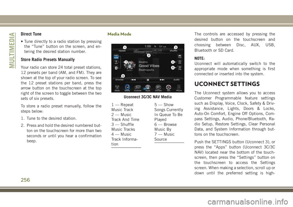
1 — Repeat
Music Track
2 — Music
Track And Time
3 — Shuffle
Music Tracks
4 — Music
Track Informa-
tion5 — Show
Songs Currently
In Queue To Be
Played
6 — Browse
Music By
7 — Music
Source
MULTIMEDIA
256
Page 259 of 312

lighted, then press the preferred setting until
a check-mark appears next to the setting,
showing that setting has been selected. The
following feature settings are available:
• Display• Engine Off Options
• Voice • Audio
• Clock • Phone/Bluetooth
• Safety & Driving
Assistance • Radio Setup
• Lights • Restore Settings
• Doors & Locks • Clear Personal Data
• Auto-On Comfort • System Information
• Compass
(Uconnect 3)
NOTE:
Depending on the vehicles options, feature
settings may vary.
Refer to “Uconnect Settings” in “Multime-
dia” in the Owner’s Manual for further infor-
mation.
IPOD/USB/SD CARD/MEDIA
PLAYER CONTROL
There are many ways to play music from
MP3 players, USB devices, or SD Cards
through your vehicle's sound system. Press
your Media button on the touchscreen to
begin.
Audio Jack (AUX)
• The AUX allows a device to be plugged into the radio and utilize the vehicle’s sound
system, using a 3.5 mm audio cable, to
amplify the source and play through the
vehicle speakers.
• Pressing the “AUX” button on the touch- screen will change the mode to auxiliary
device if the audio jack is connected, allow-
ing the music from your device to be heard
through the vehicle's speakers. To activate
the AUX, plug in the audio jack.
• The functions of the device are controlled using the device buttons. The volume may
be controlled using the radio or device.
USB Port
• Connect your compatible device into theUSB Port using a USB cable. USB Memory
sticks with audio files can also be used.
Audio from the device can be played on the
vehicle’s sound system while providing
metadata (artist, track title, album, etc.)
information on the radio display.
Uconnect Media Hub
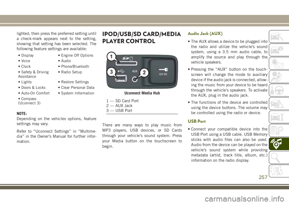
1 — SD Card Port
2 — AUX Jack
3 — USB Port
257