Page 265 of 552

5-19
Driving your vehicle
5
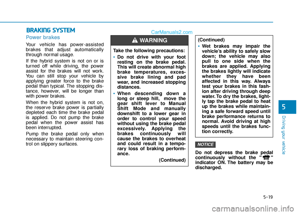
Power brakes
Your vehicle has power-assisted
brakes that adjust automatically
through normal usage.
If the hybrid system is not on or is
turned off while driving, the power
assist for the brakes will not work.
You can still stop your vehicle by
applying greater force to the brake
pedal than typical. The stopping dis-
tance, however, will be longer than
with power brakes.
When the hybrid system is not on,
the reserve brake power is partially
depleted each time the brake pedal
is applied. Do not pump the brake
pedal when the power assist has
been interrupted.
Pump the brake pedal only when
necessary to maintain steering con-
trol on slippery surfaces.Do not depress the brake pedal
continuously without the " "
indicator ON. The battery may be
discharged.
NOTICE
B
BR
RA
A K
KI
IN
N G
G
S
S Y
Y S
ST
T E
EM
M
Take the following precautions:
Do not drive with your foot
resting on the brake pedal.
This will create abnormal high
brake temperatures, exces-
sive brake lining and pad
wear, and increased stopping
distances.
When descending down a
long or steep hill, move the
gear shift lever to Manual
Shift Mode and manually
downshift to a lower gear in
order to control your speed
without using the brake pedal
excessively. Applying the
brakes continuously will
cause the brakes to overheat
and could result in a tempo-
rary loss of braking perform-
ance.
(Continued)
(Continued)
Wet brakes may impair the
vehicle’s ability to safely slow
down; the vehicle may also
pull to one side when the
brakes are applied. Applying
the brakes lightly will indicate
whether they have been
affected in this way. Always
test your brakes in this fash-
ion after driving through deep
water. To dry the brakes, light-
ly tap the brake pedal to heat
up the brakes while maintain-
ing a safe forward speed until
brake performance returns to
normal. Avoid driving at high
speeds until the brakes func-
tion correctly.
WARNING
Page 353 of 552

5-107
Driving your vehicle
5
Chain Installation
When installing tire chains, follow the
manufacturer's instructions and
mount them as tightly possible. Drive
slowly (less than 20 mph (30 km/h))
with chains installed. If you hear the
chains contacting the body or chas-
sis, stop and tighten them. If they still
make contact, slow down until the
noise stops. Remove the tire chains
as soon as you begin driving on
cleared roads.
When mounting snow chains, park
the vehicle on level ground away
from traffic. Turn on the vehicle
Hazard Warning Flasher and place a
triangular emergency warning device
behind the vehicle (if available).
Always place the vehicle in P (Park),
apply the parking brake and turn off
the engine before installing snow
chains.When using tire chains:
Wrong size chains or improperly
installed chains can damage
your vehicle's brake lines, sus-
pension, body and wheels.
Use SAE "S" class or wire chains.
If you hear noise caused by chains contacting the body,
retighten the chain to prevent
contact with the vehicle body.
To prevent body damage, retighten the chains after driving
0.3~0.6 miles (0.5~1.0 km).
Do not use tire chains on vehi- cles equipped with aluminum
wheels. If unavoidable, use a
wire type chain.
Use wire chains less than 0.47 in (12 mm) wide to prevent damage
to the chain's connection.
Winter Precautions
Use high quality ethylene glycol
coolant
Your vehicle is delivered with high
quality ethylene glycol coolant in the
cooling system. It is the only type of
coolant that should be used because
it helps prevent corrosion in the cool-
ing system, lubricates the water
pump and prevents freezing. Be sure
to replace or replenish your coolant
in accordance with the maintenance
schedule in section 7. Before winter,
have your coolant tested to assure
that its freezing point is sufficient for
the temperatures anticipated during
the winter.
NOTICE
Page 368 of 552

6-7
What to do in an emergency
6
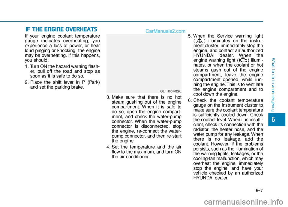
If your engine coolant temperature
gauge indicates overheating, you
experience a loss of power, or hear
loud pinging or knocking, the engine
may be overheating. If this happens,
you should:
1. Turn ON the hazard warning flash-er, pull off the road and stop as
soon as it is safe to do so.
2. Place the shift lever in P (Park) and set the parking brake.
3. Make sure that there is no hotsteam gushing out of the engine
compartment. When it is safe to
do so, open the engine compart-
ment, and check the water-pump
connector. When the water-pump
connector is disconnected, stop
the engine, re-connect the water-
pump connector, and then re-start
the engine.
4. Set the temperature and the air flow to the maximum, and turn ON
the air conditioner. 5. When the Service warning light
( ) illuminates on the instru-
ment cluster, immediately stop the
engine, and contact an authorized
HYUNDAI dealer. When the
engine warning light ( ) illumi-
nates, or when the coolant or hot
steams gush out of the engine
compartment, leave the engine
compartment opened, while run-
ning the engine. This is to ventilate
the engine compartment and to
cool down the engine.
6. Check the coolant temperature gauge on the instrument cluster to
make sure the coolant temperature
is sufficiently cooled down. Check
the coolant level. When it is insuffi-
cient, check its connection with the
radiator, the heater hose, and the
water pump for any leakage. When
there is no leakage, add the
coolant. However, if the problems
persists, such as the illumination of
the warning lights, leakages, or the
cooling-fan malfunction, which may
overheat the engine, immediately
stop the engine, and have your
vehicle checked by an authorized
HYUNDAI dealer.
I
IF
F
T
T H
H E
E
E
E N
N G
GI
IN
N E
E
O
O V
VE
ER
R H
H E
EA
A T
TS
S
OLFH067029L
Page 456 of 552
7-61
7
Maintenance
Engine compartment main fuse panel
Fuse No.Fuse NameFuse RatingCircuit Protected
MULTI FUSE(TYPE A)
IG230APCB Block (IG2 Relay)
BLOWER40ABlower Relay
2AHB40AIntegrated Brake Actuation Unit, Multipurpose Check Connector
1AHB40AIntegrated Brake Actuation Unit, Multipurpose Check Connector
REAR HEATED50ARear Heated Relay
3B+50AIGPM (IPS2 (4CH), IPS3 (4CH), Fuse - STOP LAMP/MODULE 1)
5B+50APCM Block
(Fuse - WIPER1/HORN/BATTERY C/FAN/AMS/TCU1/ECU2/Engine Control Relay)
EEWP60AElectric Water Pump
MDPS 180AMDPS Unit
MULTI FUSE(TYPE B)
IG140APCB Block (IG1Relay)
3POWER
OUTLET40APower Outlet Relay
Page 459 of 552
7-64
Maintenance
Engine compartment main fuse panel - PCB Block
Fuse NameFuse ratingCircuit Protected
ECU 310APCM
HEV ECU 210AHPCU
POWER
OUTLET 120AFront Power Outlet #1
HORN20AHorn Relay, ICM Relay Box (Burglar Alarm Horn Relay)
WIPER 130AWiper Power Relay
BATTERY C/FAN15AE/R Junction Block (Battery C/Fan Relay)
TCU 215ATransmission Range Switch, Electric Water Pump (Engine)
AHB 310AIntegrated Brake Actuation Unit
POWER
OUTLET 220ARear Power Outlet
B/UP LAMP10APCM, Transmission Range Switch, Electro Chromic Mirror, Rear Combination Lamp (In) LH/RH
SENSOR 115AOxygen Sensor (Up)/(Down)
Page 460 of 552
7-65
7
Maintenance
Engine compartment main fuse panel - PCB Block
Fuse NameFuse ratingCircuit Protected
IGN COIL20AIgnition Coil #1/#2/#3/#4
ECU 210APCM
TCU 110APCM
OPCU 210AElectric Oil Pump Unit (Control)
EWP10AElectric Water Pump (HEV)
ECU 120APCM
SENSOR 210A
Mass Air Flow Sensor, Oil Control Valve #1 (Intake), Oil Control Valve #2 (Exhaust),
Purge Control Solenoid Valve, Camshaft Position Sensor #1 (Intake),
Camshaft Position Sensor #2 (Exhaust),
E/R Junction Block (Cooling Fan Relay, Fuel Pump Relay)
AMS10ABattery Sensor