2018 Hyundai Sonata charging
[x] Cancel search: chargingPage 235 of 522
3-150
Wireless Cellular Phone
Charging System (if equipped)
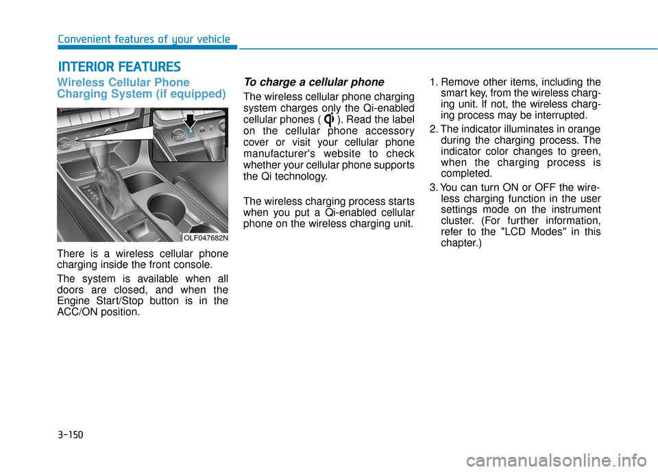
There is a wireless cellular phone
charging inside the front console.
The system is available when all
doors are closed, and when the
Engine Start/Stop button is in the
ACC/ON position.
To charge a cellular phone
The wireless cellular phone charging
system charges only the Qi-enabled
cellular phones ( ). Read the label
on the cellular phone accessory
cover or visit your cellular phone
manufacturer's website to check
whether your cellular phone supports
the Qi technology.
The wireless charging process starts
when you put a Qi-enabled cellular
phone on the wireless charging unit.1. Remove other items, including the
smart key, from the wireless charg-
ing unit. If not, the wireless charg-
ing process may be interrupted.
2. The indicator illuminates in orange during the charging process. The
indicator color changes to green,
when the charging process is
completed.
3. You can turn ON or OFF the wire- less charging function in the user
settings mode on the instrument
cluster. (For further information,
refer to the "LCD Modes" in this
chapter.)
I IN
N T
TE
ER
R I
IO
O R
R
F
F E
E A
A T
TU
U R
RE
ES
S
Convenient features of your vehicle
OLF047682N
Page 236 of 522
3-151
Convenient features of your vehicle
Slightly change the cellular phone
position, when the cellular phone is
not being charged. Make sure that
the indicator illuminates in orange.
The indicator color may not change
to green in accordance with the cel-
lular phone type, even though the
charging process is completed. The
indicator blinks in orange for 10 sec-
onds when there is a malfunction
with the wireless charging system. In
this case, temporarily stop the charg-
ing process, and re-attempt to wire-
lessly charge your cellular phone
again.
The system warns you with a mes-
sage on the LCD display when you
do not take out the cellular phone
from the wireless charging unit with
the front door open and the Engine
Start/Stop button in the OFF posi-
tion. The wireless cellular phone
charging system may not sup-
port certain cellular phones,
which are not verified for the Qi
specification ( ).
Locate your cell phone well in the middle of the wireless cellu-
lar phone charging system.
Even when your cell phone
locates slightly to one side, the
charging speed may decrease.
The wireless charging process may temporarily stop, when a
smart key function operates (i.e.
starting the engine, opening the
doors, closing the doors).
For certain cell phones, the indi- cator color may not change to
green, even when the wireless
charging process is properly
completed.
(Continued)(Continued)
The wireless charging process
may temporarily stop, when tem-
perature abnormally increases
inside the wireless cellular
phone charging system. The
wireless charging process
restarts, when temperature falls
to a proper level.
The wireless charging process may temporarily stop when
there is any metallic item, such
as a coin, between the wireless
cellular phone charging system
and a cellular phone.NOTICE
3
Page 257 of 522
5-7
Driving your vehicle
5
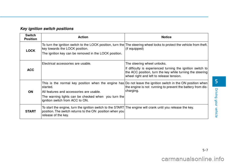
Key ignition switch positions
Switch
PositionActionNotice
LOCK
To turn the ignition switch to the LOCK position, turn the
key towards the LOCK position.
The ignition key can be removed in the LOCK position.The steering wheel locks to protect the vehicle from theft.
(if equipped)
ACC
Electrical accessories are usable.The steering wheel unlocks.
If difficulty is experienced turning the ignition switch to
the ACC position, turn the key while turning the steering
wheel right and left to release tension.
ON
This is the normal key position when the engine has
started.
All features and accessories are usable.
The warning lights can be checked when you turn the
ignition switch from ACC to ON.Do not leave the ignition switch in the ON position when
the engine is not running to prevent the battery from dis-
charging.
START
To start the engine, turn the ignition switch to the START
position. The switch returns to the ON position when you
release of the key.The engine will crank until you release the key.
Page 260 of 522
5-10
Driving your vehicle
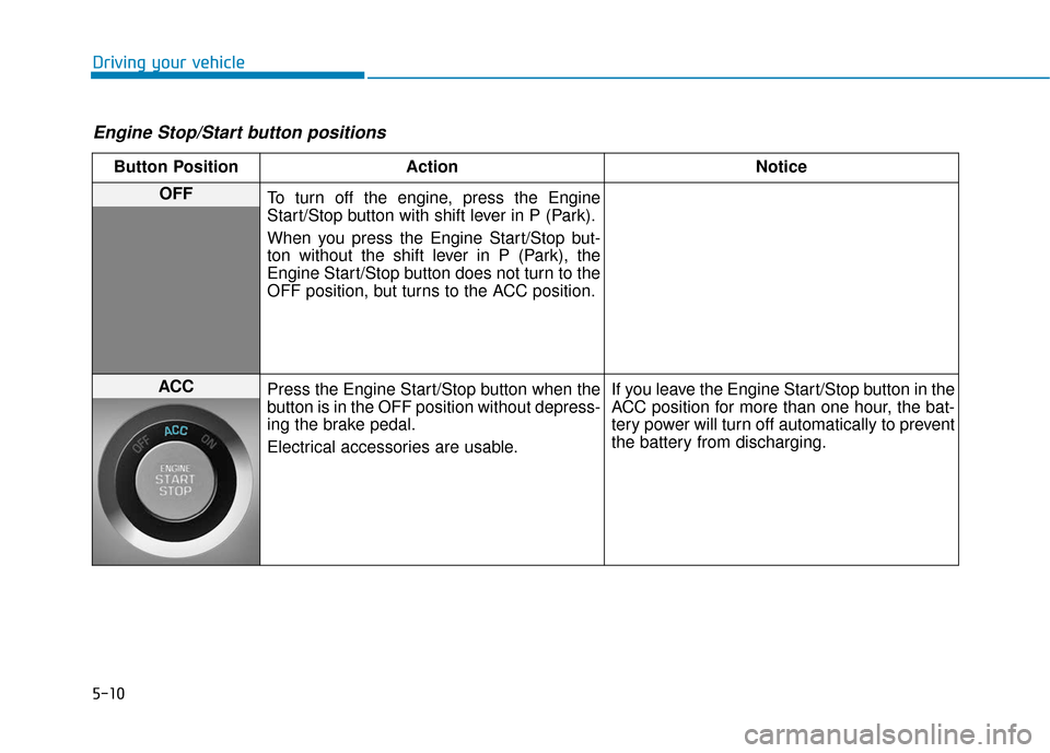
Engine Stop/Start button positions
Button PositionAction Notice
OFF
To turn off the engine, press the Engine
Start/Stop button with shift lever in P (Park).
When you press the Engine Start/Stop but-
ton without the shift lever in P (Park), the
Engine Start/Stop button does not turn to the
OFF position, but turns to the ACC position.
ACC Press the Engine Start/Stop button when the
button is in the OFF position without depress-
ing the brake pedal.
Electrical accessories are usable. If you leave the Engine Start/Stop button in the
ACC position for more than one hour, the bat-
tery power will turn off automatically to prevent
the battery from discharging.
Page 261 of 522
5-11
Driving your vehicle
5
Button PositionAction Notice
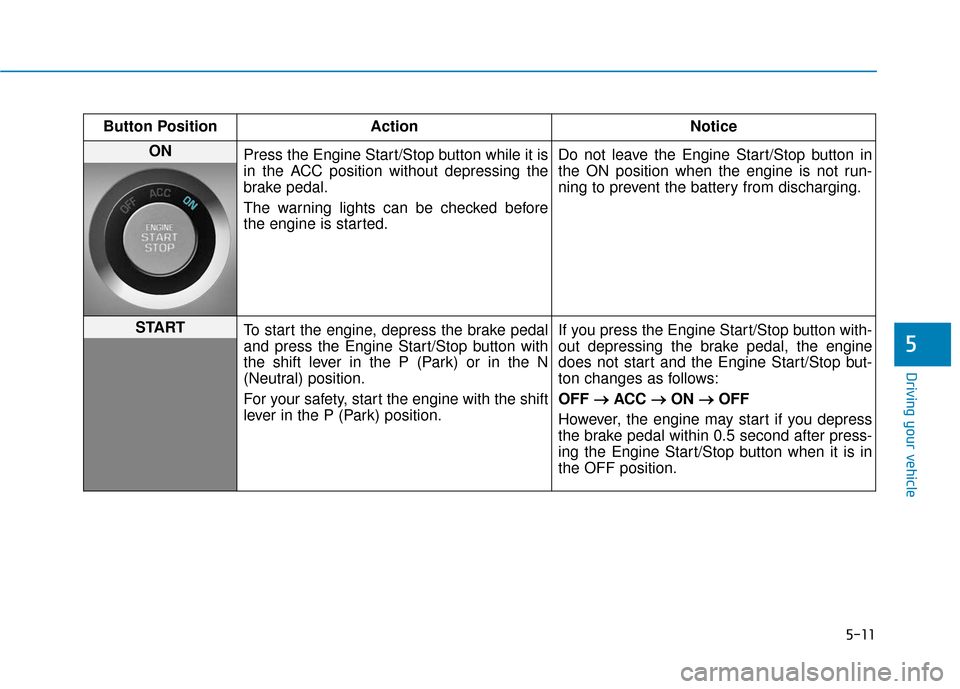
ON
Press the Engine Start/Stop button while it is
in the ACC position without depressing the
brake pedal.
The warning lights can be checked before
the engine is started. Do not leave the Engine Start/Stop button in
the ON position when the engine is not run-
ning to prevent the battery from discharging.
START
To start the engine, depress the brake pedal
and press the Engine Start/Stop button with
the shift lever in the P (Park) or in the N
(Neutral) position.
For your safety, start the engine with the shift
lever in the P (Park) position. If you press the Engine Start/Stop button with-
out depressing the brake pedal, the engine
does not start and the Engine Start/Stop but-
ton changes as follows:
OFF
→ →
ACC →
→
ON →
→
OFF
However, the engine may start if you depress
the brake pedal within 0.5 second after press-
ing the Engine Start/Stop button when it is in
the OFF position.
Page 377 of 522

6-6
What to do in an emergency
4. Connect the jumper cables in the exact sequence shown in the illus-
tration. First connect one jumper
cable to the red, positive (+)
jumper terminal of your vehicle
(1).
5. Connect the other end of the jumper cable to the red, positive
(+) battery/jumper terminal of the
assisting vehicle (2).
6. Connect the second jumper cable to the black, negative (-) battery/
chassis ground of the assisting
vehicle (3). 7. Connect the other end of the sec-
ond jumper cable to the black,
negative (-) chassis ground of
your vehicle (4).
Do not allow the jumper cables to
contact anything except the cor-
rect battery or jumper terminals or
the correct ground. Do not lean
over the battery when making
connections.
8. Start the engine of the assisting vehicle and let it run at approxi-
mately 2,000 rpm for a few min-
utes. Then start your vehicle.
If your vehicle will not start after a
few attempts, it probably requires
servicing. In this event please seek
qualified assistance. If the cause of
your battery discharging is not
apparent, have your vehicle checked
by an authorized HYUNDAI dealer. Disconnect the jumper cables in the
exact reverse order you connected
them:
1. Disconnect the jumper cable from
the black, negative (-) chassis
ground of your vehicle (4).
2. Disconnect the other end of the jumper cable from the black, neg-
ative (-) battery/chassis ground of
the assisting vehicle (3).
3. Disconnect the second jumper cable from the red, positive (+)
battery/jumper terminal of the
assisting vehicle (2).
4. Disconnect the other end of the jumper cable from the red, positive
(+) jumper terminal of your vehicle
(1).
1VQA4001
Page 412 of 522

7
Air Cleaner ............................................................7-31
Filter Replacement ..........................................................7-31
Climate Control Air Filter ....................................7-33
Filter Inspection ...............................................................7-33
Wiper Blades.........................................................7-35
Blade Inspection ..............................................................7-35
Blade Replacement .........................................................7-35
Battery...................................................................7-37
For Best Battery Service ..............................................7-38
Battery Recharging ........................................................7-38
Reset features .................................................................7-39
Tires and Wheels .................................................7-40
Tire Care ........................................................................\
....7-40
Recommended Cold Tire Inflation Pressures ...........7-41
Check Tire Inflation Pressure ......................................7-42
Tire Rotation...................................................................\
..7-43
Wheel Alignment and Tire Balance ............................7-44
Tire Replacement ............................................................7-44
Wheel Replacement ........................................................7-45
Tire Traction .....................................................................7-4\
5
Tire Maintenance ............................................................7-46
Tire Sidewall Labeling ....................................................7-46
Tire Terminology and Definitions................................7-50
All Season Tires ...............................................................7-53Summer Tires ...................................................................7-53
Snow Tires ........................................................................\
7-53
Radial-Ply Tires ...............................................................7-54
Low Aspect Ratio Tires..................................................7-54
Fuses ......................................................................7-\
56
Instrument Panel Fuse Replacement..........................7-57
Engine Compartment Panel Fuse Replacement.......7-58
Fuse/Relay Panel Description ......................................7-60
Light Bulbs ............................................................7-68
Headlamp, Position Lamp, Turn Signal Lamp and
Side Marker Light Bulb Replacement ........................7-69
Side Repeater Lamp Replacement ..............................7-72
Rear Combination Light Bulb Replacement ..............7-72
High Mounted Stop Lamp .............................................7-74
License Plate Light Bulb Replacement ......................7-75
Interior Light Bulb Replacement .................................7-75
Appearance Care..................................................7-77
Exterior Care ....................................................................7-77\
Interior Care .....................................................................7-8\
2
Emission Control System ....................................7-85
Crankcase Emission Control System ..........................7-85
Evaporative Emission Control System Including
Onboard Refueling Vapor Recovery (ORVR)............7-85
Exhaust Emission Control System ..............................7-86
California Perchlorate Notice.............................7-89
Page 448 of 522
7-38
Maintenance
When you do not use the vehicle for a long time in a low tempera-
ture area, disconnect the battery
and keep it indoors.
Always charge the battery fully to prevent battery case damage
in low temperature areas.
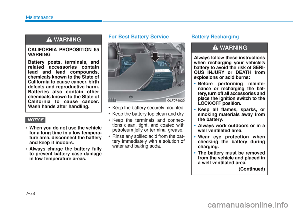
For Best Battery Service
Keep the battery securely mounted.
Keep the battery top clean and dry.
Keep the terminals and connec-tions clean, tight, and coated with
petroleum jelly or terminal grease.
Rinse any spilled acid from the bat- tery immediately with a solution of
water and baking soda.
Battery Recharging
NOTICE
CALIFORNIA PROPOSITION 65
WARNING
Battery posts, terminals, and
related accessories contain
lead and lead compounds,
chemicals known to the State of
California to cause cancer, birth
defects and reproductive harm.
Batteries also contain other
chemicals known to the State of
California to cause cancer.
Wash hands after handling.
WARNING
OLF074020
Always follow these instructions
when recharging your vehicle’s
battery to avoid the risk of SERI-
OUS INJURY or DEATH from
explosions or acid burns:
Before performing mainte-
nance or recharging the bat-
tery, turn off all accessories and
place the ignition switch to the
LOCK/OFF position.
Keep all flames, sparks, or
smoking materials away from
the battery.
Always work outdoors or in a
well ventilated area.
Wear eye protection when
checking the battery during
charging.
The battery must be removed
from the vehicle and placed in
a well ventilated area.
(Continued)
WARNING