Page 335 of 570
543
Driving your vehicle
(Continued)In these cases, the brake warning
light comes on, the AUTO HOLD
indicator changes from green to
white, and a warning sounds and a
message will appear to inform you
that EPB has been automatically
engaged. Before driving off again,
press foot brake pedal, check the
surrounding area near your vehi-
cle and release parking brake
manually with the EPB switch.
• If the AUTO HOLD indicator lights up yellow, the Auto Hold is
not working properly. Contact an
authorized HYUNDAI dealer.
• While operating Auto Hold, you may hear mechanical noise.
However, it is normal operating
noise.
WARNING
Press the accelerator pedal
slowly when you start the
vehicle.
For your safety, cancel the Auto Hold when you drive
downhill or back up the vehi-
cle or park the vehicle.
CAUTION
If there is a malfunction with thedriver's door, engine hood orliftgate (tailgate) open detectionsystem, the Auto Hold may notwork properly.
Contact an authorized HYUNDAIdealer.
Page 436 of 570
What to do in an emergency
16
6
Removing and storing the
spare tire
Your spare tire is stored underneath
your vehicle, directly below the cargo
area.
To remove the spare tire:
1.Open the liftgate (tailgate).
2.Remove cover with coin or flat-
head screwdriver. 3.Connect the wheel lug nut wrench.
4.Loosen the bolt enough to lower
the spare tire.
Turn the wrench counterclockwise
until the spare tire reaches the
ground.
(Continued)
Do not start or run the enginewhile the vehicle is on the
jack.
Do not allow anyone to remain in the vehicle while it is on the
jack.
Make sure any children pres- ent are in a secure place away
from the road and from the
vehicle to be raised with the
jack.
ONCNEM2001
ONCNEM2002
Page 446 of 570
What to do in an emergency
26
6
When towing your vehicle in an
emergency without wheel dollies :
1. Set the ignition switch in the ACC
position.
2. Place the shift lever in N (Neutral).
3. Release the parking brake.Removable towing hook
(if equipped)
1. Open the liftgate (tailgate), and remove the towing hook from the
tool case.
2. Remove the hole cover pressing the lower part of the cover on the
bumper. 3. Install the towing hook by turning it
clockwise into the hole until it is
fully secured.
4. Remove the towing hook and install the cover after use.
CAUTION
Failure to place the transaxleshift lever in N (Neutral) maycause internal damage to thetransaxle.
ONC066028
ONC066026
■Front
■Rear
Page 529 of 570
781
Maintenance
Rear combination lamp bulb
replacement
(1) Rear stop and tail lamp
(2) Rear turn signal lamp
(3) Back-up lamp
(4) Rear side marker(1) Rear stop and tail lamp
(2) Rear tail lamp
(3) Rear turn signal lamp
(4) Back-up lamp
(5) Rear side marker
Outside lamp
1. Open the liftgate (tailgate).
2. Remove the service cover using a
flat-blade screwdriver.
3. Loosen the lamp assembly retain- ing please verify.
4. Remove the rear combination lamp assembly from the body of
the vehicle.
ONC076014
ONC077020N
■Type B
■Type A
Page 530 of 570
Maintenance
82
7
5. Remove the socket from the
assembly by turning the socket
counterclockwise until the tabs on
the socket align with the slots on
the assembly. 6. Remove the bulb from the socket
by pressing it in and rotating it
counterclockwise until the tabs on
the bulb align with the slots in the
socket. Pull the bulb out of the
socket. (Side marker : Remove the
bulb from the socket by pulling it
out)
7. Insert a new bulb by inserting it into the socket and rotating it until
it locks into place.
8. Install the socket in the assembly by aligning the tabs on the socket
with the slots in the assembly.
Push the socket into the assembly
and turn the socket clockwise.
9. Reinstall the lamp assembly to the body of the vehicle.
Inside lamp
1. Open the liftgate (tailgate).
2. Remove the service cover using aflat-blade screwdriver.
OANNMC2036
ODM076104L
ODM076103L
■
Type A
■ Type B
Page 532 of 570
Maintenance
84
7
High mounted stop lamp
replacement
1. Open the liftgate (tailgate).
2. Gently remove the center cover of
the rear liftgate (tailgate) trim.
3. Disconnect the electrical connec- tor. 4. Loosen the retaining nuts and
remove the spoiler. 5. Remove the high mounted stop
lamp assembly (A) after loosening
the nuts and washer nozzle (B).
6. Reinstall a new lamp assembly in the reverse order of removal.
ONCNMC3204
ODMEMC2021
B
A
ODMEMC2022
Page 565 of 570

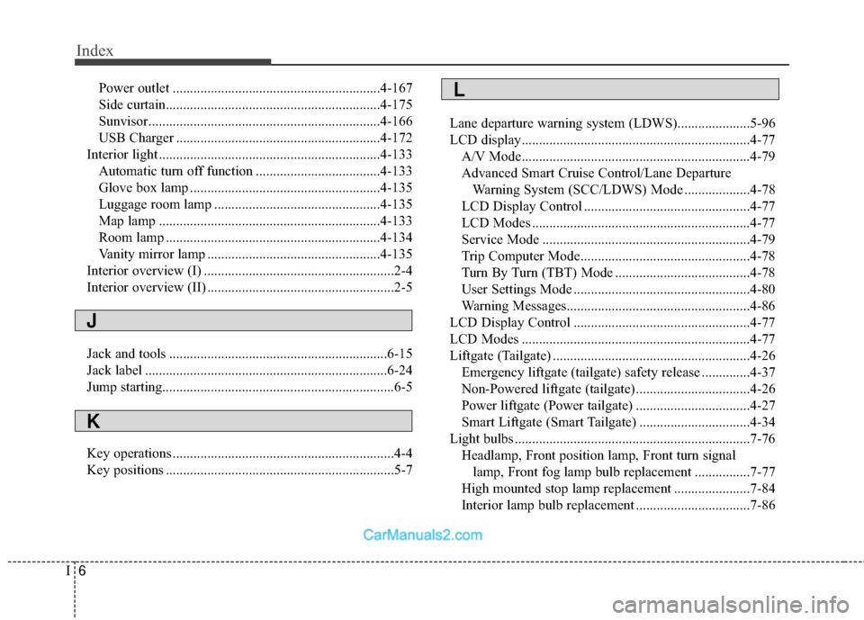
Index
6I
Power outlet ............................................................4-167
Side curtain..............................................................4-175
Sunvisor...................................................................4-166\
USB Charger ...........................................................4-172
Interior light ................................................................4-133 Automatic turn off function ....................................4-133
Glove box lamp .......................................................4-135
Luggage room lamp ................................................4-135
Map lamp ................................................................4-133
Room lamp ..............................................................4-134
Vanity mirror lamp ..................................................4-135
Interior overview (I) .......................................................2-4
Interior overview (II) ......................................................2-5
Jack and tools ...............................................................6-15
Jack label ......................................................................6-\
24
Jump starting...........................................................\
........6-5
Key operations ................................................................4-4
Key positions ..................................................................5-7 Lane departure warning system (LDWS).....................5-96
LCD display..................................................................4-77
A/V Mode..................................................................4-79
Advanced Smart Cruise Control/Lane Departure Warning System (SCC/LDWS) Mode ...................4-78
LCD Display Control ................................................4-77
LCD Modes ...............................................................4-77
Service Mode ............................................................4-79
Trip Computer Mode.................................................4-78
Turn By Turn (TBT) Mode .......................................4-78
User Settings Mode ...................................................4-80
Warning Messages.....................................................4-86
LCD Display Control ...................................................4-77
LCD Modes ..................................................................4-77
Liftgate (Tailgate) .........................................................4-26 Emergency liftgate (tailgate) safety release ..............4-37
Non-Powered liftgate (tailgate).................................4-26
Power liftgate (Power tailgate) .................................4-27
Smart Liftgate (Smart Tailgate) ................................4-34
Light bulbs ....................................................................7-76\
Headlamp, Front position lamp, Front turn signal lamp, Front fog lamp bulb replacement ................7-77
High mounted stop lamp replacement ......................7-84
Interior lamp bulb replacement .................................7-86
J
K
L
Page 566 of 570

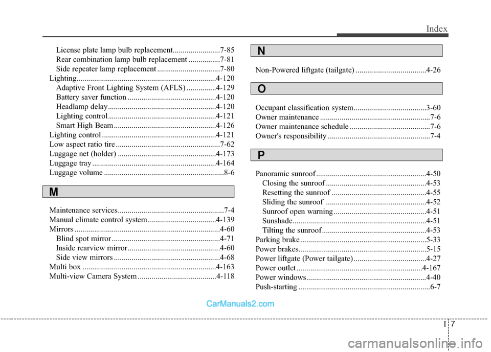
I7
Index
License plate lamp bulb replacement........................7-85
Rear combination lamp bulb replacement ................7-81
Side repeater lamp replacement ................................7-80
Lighting................................................................\
.......4-120 Adaptive Front Lighting System (AFLS) ...............4-129
Battery saver function .............................................4-120
Headlamp delay.......................................................4-120
Lighting control.......................................................4-121
Smart High Beam ....................................................4-126
Lighting control ..........................................................4-121
Low aspect ratio tire .....................................................7-62
Luggage net (holder) ..................................................4-173
Luggage tray ...............................................................4-164
Luggage volume .............................................................8-6
Maintenance services......................................................7-4
Manual climate control system...................................4-139
Mirrors ........................................................................\
..4-60 Blind spot mirror .......................................................4-71
Inside rearview mirror...............................................4-60
Side view mirrors ......................................................4-68
Multi box ....................................................................4-16\
3
Multi-view Camera System ........................................4-118 Non-Powered liftgate (tailgate) ....................................4-26
Occupant classification system.....................................3-60
Owner maintenance ........................................................7-6
Owner maintenance schedule .........................................7-6
Owner's responsibility ....................................................7-4
Panoramic sunroof ........................................................4-50
Closing the sunroof ...................................................4-53
Resetting the sunroof ................................................4-55
Sliding the sunroof ...................................................4-52
Sunroof open warning ...............................................4-51
Sunshade....................................................................4-51\
Tilting the sunroof .....................................................4-53
Parking brake ................................................................5-33
Power brakes............................................................\
.....5-15
Power liftgate (Power tailgate) .....................................4-27
Power outlet ................................................................4-167
Power windows...........................................................\
..4-40
Push-starting ...................................................................6-7
M
N
O
P