2018 Hyundai Kona coolant temperature
[x] Cancel search: coolant temperaturePage 436 of 523

7-24
Maintenance
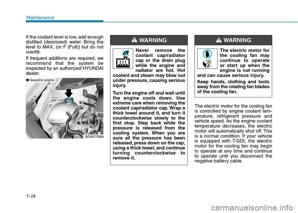
If the coolant level is low, add enough
distilled (deionized) water. Bring the
level to MAX, (or F (Full)) but do not
overfill.
If frequent additions are required, werecommend that the system be
inspected by an authorized HYUNDAI
dealer.
The electric motor for the cooling fan
is controlled by engine coolant tem-
perature, refrigerant pressure and
vehicle speed. As the engine coolant
temperature decreases, the electric
motor will automatically shut off. This
is a normal condition. If your vehicle
is equipped with T-GDI, the electric
motor for the cooling fan may begin
to operate at any time and continue
to operate until you disconnect the
negative battery cable.
OOS077009
■Gasoline engine The electric motor for
the cooling fan may
continue to operate
or start up when theengine is not running
and can cause serious injury.
Keep hands, clothing and tools
away from the rotating fan bladesof the cooling fan.
WARNING
Never remove the
coolant cap/radiator cap or the drain plugwhile the engine and
radiator are hot. Hot
coolant and steam may blow out
under pressure, causing serious
injury.
Turn the engine off and wait until
the engine cools down. Use
extreme care when removing the
coolant cap/radiator cap. Wrap a
thick towel around it, and turn it
counterclockwise slowly to the
first stop. Step back while the
pressure is released from the
cooling system. When you aresure all the pressure has been
released, press down on the cap,
using a thick towel, and continue
turning counterclockwise to
remove it.
WARNING
Page 437 of 523

7-25
7
Maintenance
Recommended engine coolant
When adding coolant, use only dis-tilled (deionized) water for your
vehicle and never mix hard water in
the coolant filled at the factory. Anincorrect coolant mixture can result
in serious malfunction or engine
damage.
The engine in your vehicle has alu- minum engine parts and must be
protected by an ethylene-glycolwith phosphate based coolant to
prevent corrosion and freezing.
DO NOT USE alcohol or methanol coolant or mix them with the spec-ified coolant.
Do not use a solution that contains more than 60% antifreeze or less
than 35% antifreeze, which would
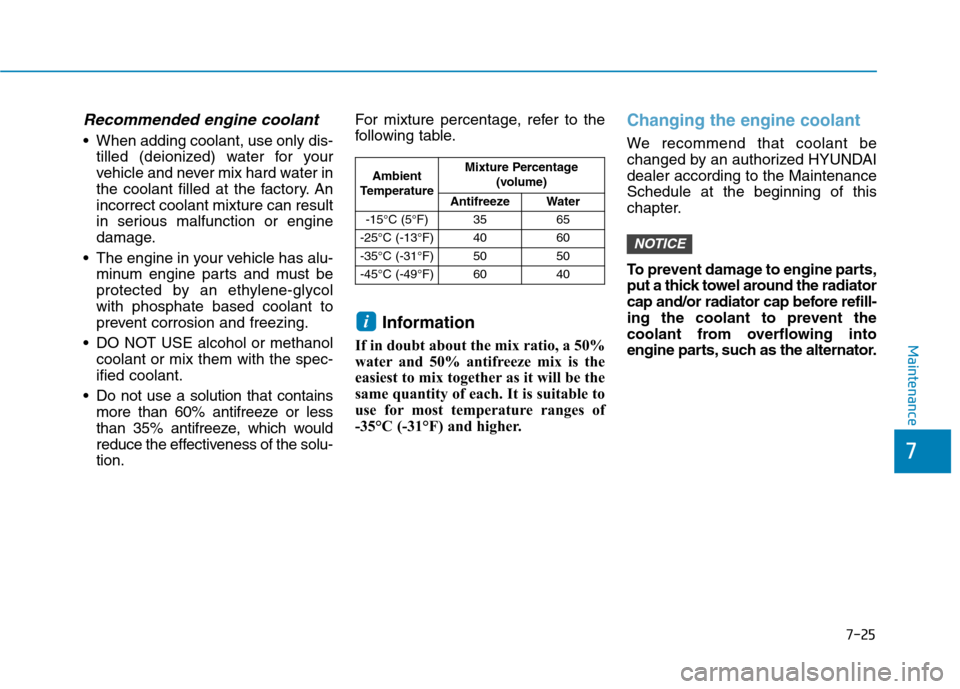
reduce the effectiveness of the solu-tion. For mixture percentage, refer to the
following table.
Information
If in doubt about the mix ratio, a 50%
water and 50% antifreeze mix is the
easiest to mix together as it will be the
same quantity of each. It is suitable to
use for most temperature ranges of
-35°C (-31°F) and higher.
Changing the engine coolant
We recommend that coolant be
changed by an authorized HYUNDAIdealer according to the MaintenanceSchedule at the beginning of this
chapter.
To prevent damage to engine parts,
put a thick towel around the radiator
cap and/or radiator cap before refill-
ing the coolant to prevent the
coolant from overflowing into
engine parts, such as the alternator.
NOTICE
i
Ambient
Temperature Mixture Percentage
(volume)
Antifreeze Water
-15°C (5°F) 35 65
-25°C (-13°F) 40 60
-35°C (-31°F) 50 50
-45°C (-49°F) 60 40
Page 497 of 523

7-85
7
Maintenance
EEMM IISS SSIIOO NN CC OO NNTTRR OO LL SS YY SSTT EEMM
The emission control system of your
vehicle is covered by a written limited
warranty. Please see the warranty
information contained in the Service
Passport in your vehicle.
Your vehicle is equipped with an emission control system to meet all
emission regulations. There are three emission control
systems which are as follows.
(1) Crankcase emission control sys-
tem
(2) Evaporative emission control sys- tem
(3) Exhaust emission control systemIn order to ensure the proper function
of the emission control systems, it is
recommended that you have your car
inspected and maintained by an
authorized HYUNDAI dealer in accor-dance with the maintenance schedule
in this manual.
1. Crankcase emission control system
The positive crankcase ventilation
system is employed to prevent air
pollution caused by blow-by gases
being emitted from the crankcase.This system supplies fresh filtered air
to the crankcase through the air
intake hose. Inside the crankcase,
the fresh air mixes with blow-by
gases, which then pass through the
PCV valve into the induction system.
2. Evaporative emission con-trol system
The Evaporative Emission Control
System is designed to prevent fuel
vapors from escaping into the atmos-
phere.
Canister
Fuel vapors generated inside the fueltank are absorbed and stored in the
onboard canister. When the engine is
running, the fuel vapors absorbed in
the canister are drawn into the surgetank through the purge control sole-
noid valve.
Purge Control Solenoid Valve
(PCSV)
The purge control solenoid valve is
controlled by the Engine Control
Module (ECM); when the engine
coolant temperature is low during
idling, the PCSV closes so that evap-
orated fuel is not taken into the
engine. After the engine warms-up
during ordinary driving, the PCSV
opens to introduce evaporated fuel to
the engine.
For the Inspection and Maintenance
Test (with Electronic Stability Control(ESC) system)
To prevent the vehicle from
misfiring during dynamome-
ter testing, turn the Electronic
Stability Control (ESC) sys-
tem off by pressing the ESC
switch.
After dynamometer testing is
completed, turn the ESC sys-
tem back on by pressing the
ESC switch again.
CAUTION
Page 516 of 523

I-5
Engine compartment ...............................................1-8, 7-3
Engine compartment panel fuse replacement...............7-48
Engine coolant ..............................................................7-23
Engine coolant temperature gauge ...............................3-39
Engine number ..............................................................8-11
Engine oil......................................................................7-21
Engine specification .......................................................8-2
Engine start/stop button ..................................................5-9
Evaporative emission control System ..........................7-85
Exhaust emission control system .................................7-86
Explanation of scheduled maintenance items ..............7-19
Exterior care .................................................................7-78
Exterior overview ..........................................................1-2
Front view ..................................................................1-2
Rear view ...................................................................1-3
Floor mat anchor(s) ....................................................3-136
Fluid Brake/clutch fluid.....................................................7-26
Washer fluid .............................................................7-27
Forward Collision-Avoidance Assist (FCA) system ....5-63
Four Wheel Drive (4WD).............................................5-41
Front seat adjustment......................................................2-7 Manual adjustment .....................................................2-7
Power adjustment .......................................................2-9
Seatback pocket........................................................2-11
Adjusting the height up and down ...........................2-16 Forward and rearward adjustment ...........................2-16
Removal/Reinstall ....................................................2-17
Fuel filler door ..............................................................3-34
Fuel gauge.....................................................................3-39
Fuel requirements ...........................................................F-6
Unleaded ....................................................................F-6
Leaded ........................................................................F-7
Gasoline containing alcohol and methanol................F-7
Other fuels..................................................................F-7
Use of MTBE.............................................................F-8
Do not use methanol ..................................................F-8
Fuel Additives ............................................................F-8
Operation in foreign countries ...................................F-8
Fuses .............................................................................7-46 Instrument panel fuse replacement ..........................7-47
Fuse switch...............................................................7-48
Blade type fuse.........................................................7-48
Cartridge type fuse ...................................................7-48
Engine compartment panel fuse replacement ..........7-48
Main fuse..................................................................7-49
Multi fuse .................................................................7-49
Fuse/relay panel description ....................................7-50
Gauges and meters........................................................3-38
Glove box ...................................................................3-128
I
Index
F
G