2018 Hyundai Ioniq Hybrid check engine
[x] Cancel search: check enginePage 571 of 642

7-64
Maintenance
TypeSymbolFuse RatingCircuit Protected
Multi Fuse
PTC
HEATER250AEngine Room Junction Block
CLUTCH
ACTUATOR40AClutch Actuator
Fuse
DCT315ATCM
HPCU110AHPCU
EWP10AElectric Water Pump (HEV)
140AIGPM
DCT240ATCM
DCT140ATCM
10AEngine Room Junction Block
1
ACTIVE
HYDRAULIC
BOSSTER40AMultipurpose Check Connector, IBAU
2
ACTIVE
HYDRAULIC
BOSSTER30AMultipurpose Check Connector, IBAU
POWER
OUTLET140AEngine Room Junction Block
B/UP
LAMP10AAudio, Rear Combination Lamp (IN) LH/RH, Electro Chromic Mirror
Engine compartment fuse panel
Page 572 of 642

7-65
7
Maintenance
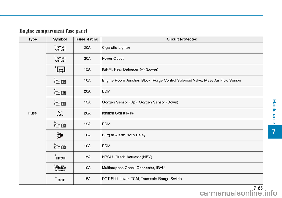
TypeSymbolFuse RatingCircuit Protected
Fuse
POWER
OUTLET320ACigarette Lighter
POWER
OUTLET220APower Outlet
215AIGPM, Rear Defogger (+) (Lower)
S210AEngine Room Junction Block, Purge Control Solenoid Valve, Mass Air Flow Sensor
E120AECM
S115AOxygen Sensor (Up), Oxygen Sensor (Down)
IGN
COIL20AIgnition Coil #1~#4
E215AECM
10ABurglar Alarm Horn Relay
E310AECM
HPCU215AHPCU, Clutch Actuator (HEV)
3
ACTIVE
HYDRAULIC
BOSSTER10AMultipurpose Check Connector, IBAU
DCT415ADCT Shift Lever, TCM, Transaxle Range Switch
Engine compartment fuse panel
Page 584 of 642

7-77
7
Maintenance
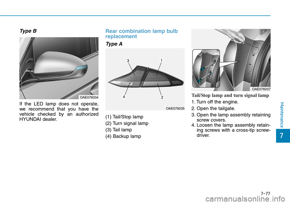
Type B
If the LED lamp does not operate,
we recommend that you have the
vehicle checked by an authorized
HYUNDAI dealer.
Rear combination lamp bulb
replacement
Type A
(1) Tail/Stop lamp
(2) Turn signal lamp
(3) Tail lamp
(4) Backup lamp
Tail/Stop lamp and turn signal lamp
1. Turn off the engine.
2. Open the tailgate.
3. Open the lamp assembly retaining
screw covers.
4. Loosen the lamp assembly retain-
ing screws with a cross-tip screw-
driver.OAE076034
OAE076035
OAE076037
Page 586 of 642

7-79
7
Maintenance
Tail lamp and backup lamp
1. Turn off the engine.
2. Open the tailgate.
3. Remove the service cover using a
flat-blade screwdriver.4. Remove the bulb by pulling it
straight out.
5. Insert a new bulb by inserting it
into the socket and rotating it until
it locks into place.
6. Install the socket into the assembly
by aligning the tabs on the socket
with the slots in the assembly.
Push the socket into the assembly
and turn the socket clockwise.
7. Reinstall the service cover.
Type B
(1) Tail/Stop lamp
(2) Turn signal lamp
(3) Tail lamp
(4) Backup lamp
Tail/Stop lamp
If the LED lamp does not operate, we
recommend that you have the vehi-
cle checked by an authorized
HYUNDAI dealer.
OAE076036
OAE076041OAE076042
Backup lamp
Page 600 of 642

7-93
7
Maintenance
Engine exhaust (carbon monox-
ide) precautions
• Carbon monoxide can be present
with other exhaust fumes. If you
smell exhaust fumes of any kind in
your vehicle, drive with all the win-
dows fully open. Have your vehicle
checked and repaired immediately.• Do not operate the engine in con-
fined or closed areas (such as
garages) any more than what is
necessary to move the vehicle in or
out of the area.
• When the vehicle is stopped in an
open area for more than a short
time with the engine running,
adjust the ventilation system (as
needed) to draw outside air into the
vehicle.
• Never sit in a parked or stopped
vehicle for any extended time with
the engine running.
• When the engine stalls or fails to
start, excessive attempts to restart
the engine may cause damage to
the emission control system.
Operating precautions for cat-
alytic converters (if equipped)
The exhaust system and cat-
alytic converter are very hot
during and immediately after
the engine has been running. To
avoid SERIOUS INJURY or
DEATH:
•Do not park, idle, or drive the
vehicle over or near flamma-
ble objects, such as grass,
vegetation, paper, leaves, etc.
A hot exhaust system can
ignite flammable items under
your vehicle.
•Keep away from the exhaust
system and catalytic convert-
er or you may get burned.
Also, Do not remove the heat
sink around the exhaust sys-
tem, do not seal the bottom of
the vehicle, and do not coat
the vehicle for corrosion con-
trol. It may present a fire risk
under certain conditions.
WARNING
Engine exhaust gases contain
carbon monoxide (CO). Though
colorless and odorless, it is
dangerous and could be lethal if
inhaled. Follow the instructions
on this page to avoid CO poi-
soning.
WARNING
Page 602 of 642

PROCEDURE FOR ENTERING FORCED ENGINE ACTIVATION MODE
If the engine needs to be kept run-
ning while the vehicle is stopped to
inspect emission gas or perform
vehicle maintenance, follow below
procedure to enter forced engine
activation mode.
1. Place the shift lever in P (Park)
position with the vehicle stopped.
Engage the parking brake. Then,
follow the steps (1) to (5).
Information
Below steps from (1) to (5) must be
completed within 60 sec. If not, the
process is reset and you must start
again from step (1).(1) Turn the ignition switch to the ON
position. Vehicles equipped with
the smart key, press the Engine
Start/Stop button twice without
depressing the brake pedal.
(2) Place the shift lever in P (Park)
position and depress the acceler-
ator pedal twice.
(3) Place the shift lever in N (Neutral)
position and depress the acceler-
ator pedal twice.
(4) Place the shift lever in P (Park)
position and depress the acceler-
ator pedal twice.
(5) With the brake pedal depressed,
start the engine, and maintain
idling state.
Information
The engine remains in idle state and
the forced engine activation mode is
maintained even when the gear is
shifted to a different position.2. " " indicator on the instrument
cluster blinks when the vehicle is
in forced engine activation mode.
Check the " " indicator blinking
to ensure that the forced engine
activation mode is correctly
entered.
Information
The " " indicator continues blink-
ing until the forced engine activation
mode is cancelled. When the mode is
cancelled the " " indicator will
stop blinking.
3. To cancel the forced engine acti-
vation mode, turn the vehicle off.
i
i
i
7-95
7
Maintenance
Page 609 of 642

8-7
8
Specifications & Consumer information
Recommended SAE viscosity
number
Always be sure to clean the area
around any filler plug, drain
plug, or dipstick before check-
ing or draining any lubricant.
This is especially important in
dusty or sandy areas and when
the vehicle is used on unpaved
roads. Cleaning the plug and
dipstick areas will prevent dirt
and grit from entering the
engine and other mechanisms
that could be damaged.
CAUTION
Engine oil viscosity (thickness) has an effect on fuel economy and cold
weather operating (engine start and engine oil flowability). Lower viscosity
engine oils can provide better fuel economy and cold weather performance,
however, higher viscosity engine oils are required for satisfactory lubrication
in hot weather. Using oils of any viscosity other than those recommended
could result in engine damage.
When choosing an oil, consider the range of temperature your vehicle will be
operated in before the next oil change. Proceed to select the recommended
oil viscosity from the chart.
Temperature Range for SAE Viscosity Numbers
Temperature
Gasoline Engine Oil
°C
(°F)-30 -20 -10 0 10 20 30 40 50
-10 0 20 40 60 80 100 120
20W-50
15W-40
10W-30
0/5W-30, 5W-40
Page 632 of 642

I-3
Battery (12 volt, Plug-in hybrid vehicle) .....................7-38
Battery recharging......................................................7-40
Battery cooling duct .....................................................2-24
Battery saver function .................................................3-111
Before driving .................................................................5-4
Blind spot detection (BSD) system ..............................5-40
Bluetooth
®Wireless Technology hands-free ..................4-4
Bottle holder ...............................................................3-147
Brake fluid ....................................................................7-29
Brake system.................................................................5-27
Anti-lock brake system (ABS) ..................................5-31
Disc brakes wear indicator ........................................5-28
Electronic stability control (ESC) .............................5-33
Emergency stop signal (ESS) ....................................5-38
Good braking practices ..............................................5-39
Hill-start assist control (HAC)...................................5-38
Parking brake .............................................................5-28
Power brakes..............................................................5-27
Vehicle stability management (VSM) .......................5-36
Bulb replacement
Daytime running lamp ...............................................7-76
Front position lamp....................................................7-68
Front turn signal lamp ...............................................7-68
Headlamp ...................................................................7-68
Headlamp aiming .......................................................7-72
High mounted stop lamp ...........................................7-82Interior light bulb .......................................................7-82
License plate light bulb .............................................7-82
Rear combination lamp bulb .....................................7-77
Rear fog lamp ............................................................7-82
Side repeater lamp ....................................................7-76
Bulb wattage ...................................................................8-3
Button start/stop, see engine start/stop button................5-9
Camera (Rear view)....................................................3-120
Capacities (Lubricants) ...................................................3-6
Care
Exterior care...............................................................7-84
Interior care................................................................7-89
Tire care .....................................................................7-42
Cellular phone charger................................................3-150
Center console storage................................................3-145
Central door lock switch...............................................3-14
Certification label ...........................................................8-8
Chains
Tire chains................................................................5-100
Checking tire inflation pressure ...................................7-44
Child restraint system (CRS)........................................2-38
Booster seats ..............................................................2-40
Children always in the rear ........................................2-38
Forward-facing child restraint system .......................2-40
Installing a child restraint system (CRS)...................2-41
I
Index
B
C