2018 Hyundai Creta Bumper
[x] Cancel search: BumperPage 79 of 472

2-59
Safety system of your vehicle
2
Air bag inflation conditions
Front air bags are designed to inflate
in a frontal collision depending on
the severity, speed or angles of
impact of the front collision.
Do not hit or allow any objects
to impact the locations where
air bags or sensors are
installed.
This may cause unexpected
air bag deployment, which
could result in serious per-
sonal injury or death.
If the installation location or
angle of the sensors is altered
in any way, the air bags may
deploy when they should not
or they may not deploy when
they should, causing severe
injury or death.
Therefore, do not try to perform
maintenance on or around the
air bag sensors. We recom-
mend that the system be serv-
iced by an authorized HYUNDAI
dealer.
(Continued)
WARNING (Continued)
Problems may arise if the sen-
sor installation angles are
changed due to the deforma-
tion of the front bumper, body
or B pillar where side collision
sensors are installed. We rec-
ommend that the system be
serviced by an authorized
HYUNDAI dealer.
Your vehicle has been designed
to absorb impact and deploy
the air bag(s) in certain colli-
sions. Installing aftermarket
bumper guards or replacing a
bumper with non-genuine parts
may adversely affect your vehi-
cles collision and air bag
deployment performance.
OGS035027
Page 85 of 472

2-65
Safety system of your vehicle
2
Adding equipment to or modify-
ing your air bag-equipped vehi-
cle
If you modify your vehicle by chang-
ing your vehicle's frame, bumper sys-
tem, front end or side sheet metal or
ride height, this may affect the opera-
tion of your vehicle's air bag system.
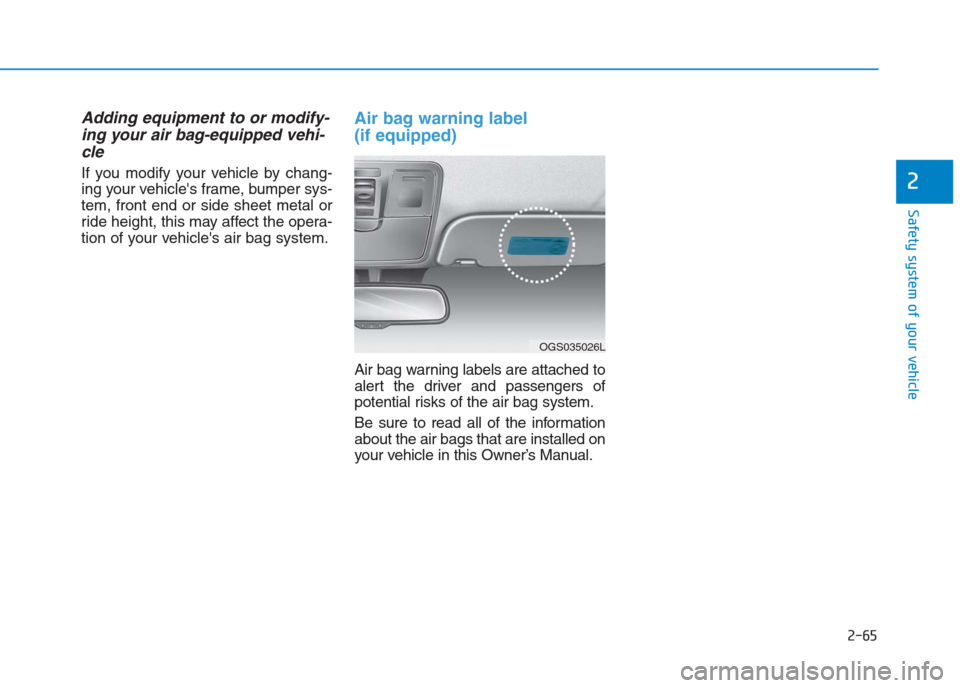
Air bag warning label
(if equipped)
Air bag warning labels are attached to
alert the driver and passengers of
potential risks of the air bag system.
Be sure to read all of the information
about the air bags that are installed on
your vehicle in this Owner’s Manual.
OGS035026L
Page 178 of 472

3-93
Convenient features of your vehicle
3
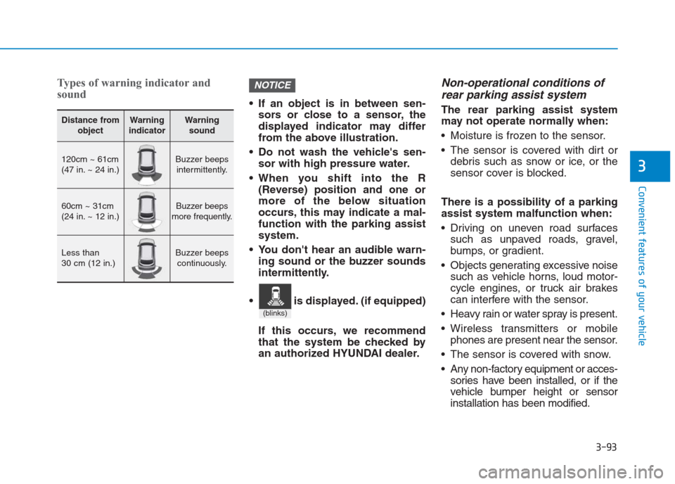
Types of warning indicator and
sound
If an object is in between sen-
sors or close to a sensor, the
displayed indicator may differ
from the above illustration.
Do not wash the vehicle's sen-
sor with high pressure water.
When you shift into the R
(Reverse) position and one or
more of the below situation
occurs, this may indicate a mal-
function with the parking assist
system.
You don't hear an audible warn-
ing sound or the buzzer sounds
intermittently.
If this occurs, we recommend
that the system be checked by
an authorized HYUNDAI dealer.
Non-operational conditions of
rear parking assist system
The rear parking assist system
may not operate normally when:
Moisture is frozen to the sensor.
The sensor is covered with dirt or
debris such as snow or ice, or the
sensor cover is blocked.
There is a possibility of a parking
assist system malfunction when:
Driving on uneven road surfaces
such as unpaved roads, gravel,
bumps, or gradient.
Objects generating excessive noise
such as vehicle horns, loud motor-
cycle engines, or truck air brakes
can interfere with the sensor.
Heavy rain or water spray is present.
Wireless transmitters or mobile
phones are present near the sensor.
The sensor is covered with snow.
Any non-factory equipment or acces-
sories have been installed, or if the
vehicle bumper height or sensor
installation has been modified.
NOTICE
Distance from
objectWarning
indicatorWarning
sound
120cm ~ 61cm
(47 in. ~ 24 in.)Buzzer beeps
intermittently.
60cm ~ 31cm
(24 in. ~ 12 in.)Buzzer beeps
more frequently.
Less than
30 cm (12 in.)Buzzer beeps
continuously.
(blinks)
is displayed. (if equipped)
Page 348 of 472

6-17
What to do in an emergency
6
Changing tires Follow these steps to change your
vehicle’s tire:
1. Park on a level, firm surface.
2. Move the shift lever into P (Park,
for automatic transaxle vehicle) or
neutral (for manual transaxle
vehicle), apply the parking brake,
and place the ignition switch in the
LOCK/OFF position.
3. Press the hazard warning flasher
button.
4. Remove the wheel lug nut wrench,
jack, jack handle, and spare tire
from the vehicle.
5. Block both the front and rear of the
tire diagonally opposite of the tire
you are changing. A vehicle can slip or roll off of a
jack causing serious injury or
death to you or those nearby.
Take the following safety pre-
cautions:
Do not get under a vehicle
that is supported by a jack.
NEVER attempt to change a
tire in the lane of traffic.
ALWAYS move the vehicle
completely off the road on
level, firm ground away from
traffic before trying to change
a tire. If you cannot find a
level, firm place off the road,
call a towing service for assis-
tance.
Be sure to use the jack pro-
vided with the vehicle.
(Continued)
(Continued)
ALWAYS place the jack on the
designated jacking positions
on the vehicle and NEVER on
the bumpers or any other part
of the vehicle for jacking sup-
port.
Do not start or run the engine
while the vehicle is on the
jack.
Do not allow anyone to remain
in the vehicle while it is on the
jack.
Keep children away from the
road and the vehicle.
WARNING
Page 354 of 472

6-23
What to do in an emergency
6
When towing your vehicle in an
emergency without wheel dollies:
1. Place the ignition switch in the
ACC position.
2. Place the shift lever in N (Neutral).
3. Release the parking brake.
Failure to place the shift lever in N
(Neutral) when being towed with
the front wheels on the ground
can cause internal damage to the
transaxle.Removable towing hook
NOTICE
OGC064010OGS068020L
OGS068021L
■Front■Rear
1. Open the trunk, and remove the
towing hook from the tool case.
2. Remove the hole cover pressing
the lower part of the cover on the
front bumper.
3. Install the towing hook by turning
it clockwise into the hole until it is
fully secured.
4. Remove the towing hook and
install the cover after use.
Page 413 of 472

7-56
Maintenance
Wheel replacement
When replacing the metal wheels for
any reason, make sure the new
wheels are equivalent to the original
factory units in diameter, rim width
and offset. Replacing tires
To reduce the chance or serious
or fatal injuries from an acci-
dent caused by tire failure or
loss of vehicle control:
Replace tires that are worn,
show uneven wear, or are
damaged. Worn tires can
cause loss of braking effec-
tiveness, steering control, and
traction.
Do not drive your vehicle with
too little or too much pressure
in your tires. This can lead to
uneven wear and tire failure.
When replacing tires, never
mix radial and bias-ply tires
on the same car. You must
replace all tires (including the
spare) if moving from radial to
bias-ply tires.
(Continued)
WARNING (Continued)
Using tires and wheel other
than the recommended sizes
could cause unusual handling
characteristics and poor vehi-
cle control, resulting in a seri-
ous accident.
When replacing tires (or
wheels), it is recommended to
replace the two front or two
rear tires (or wheels) as a pair.
Replacing just one tire can
seriously affect your vehicle’s
handling.
The ABS works by comparing
the speed of the wheels. Tire
size can affect wheel speed.
When replacing tires, all 4
tires must use the same size
originally supplied with the
vehicle. Using tires of a differ-
ent size can cause the ABS
(Anti-lock Brake System) and
ESC (Electronic Stability
Control) to work irregularly. (if
equipped)
A wheel that is not the correct
size may adversely affect wheel
and bearing life, braking and
stopping abilities, handling
characteristics, ground clear-
ance, body-to-tire clearance,
snow chain clearance,
speedometer and odometer cal-
ibration, headlight aim and
bumper height.
WARNING
Page 437 of 472

7-80
Maintenance
Parking (Position) light
1. Remove the socket from the
assembly by pulling it straight out.
2. Remove the bulb from the socket
by pulling it out.
3. Insert a new bulb by inserting it
into the socket.
4. Install the socket in the assembly
by pushing it in.
Front fog light bulb replacement
1. Remove the under cover by rotat-
ing the screws and bolts.
2. Reach your hand into the back of
the front bumper.
3. Disconnect the power connector
from the socket.
4. Remove the bulb-socket from the
housing by turning the socket
counterclockwise until the tabs on
the socket align with the slots on
the housing.
5. Install the new bulb-socket into the
housing by aligning the tabs on
the socket with the slots in the
housing. Push the socket into the
housing and turn the socket clock-
wise.
6. Connect the power connector to
the socket.
7. Reinstall the front bumper under
cover.
Information
The FOG LAMP aiming adjustment
can be done by removing UNDER
CVR. Consult an authorized
HYUNDAI Dealer.
Type B
(1) Headlight (Low/High)
(2) Parking (Position) light
(3) Front turn signal light
(4) Static bending light
(5) Front fog light (if equipped)
(6) Daytime running light
(if equipped)
i
OGS078109L
Page 439 of 472

7-82
Maintenance
6. Install a new headlight bulb and
snap the headlight bulb retaining
wire into position by aligning the
wire with the groove on the bulb.
7. Connect the headlight bulb socket
connector.
8. Install the headlight bulb cover by
turning it clockwise.
Information
-
Bi-Function projection
headlamp
This headlamp is bi-function type that
switches the low beam to high or the
high beam to low using solenoid sys-
tem. So, the moving sound may be
heard when the headlamp switches
the low beam to high or the high beam
to low and it does not indicate mal-
function of the headlamp.
Turn signal light
1. Remove the turn signal light bulb
cover by turning it counterclock-
wise.
2. Remove the socket from the
assembly by turning the socket
counterclockwise until the tabs on
the socket align with the slots on
the assembly.
3. Insert a new bulb by inserting it
into the socket and rotating it until
it locks into place.
4. Install the socket in the assembly
by aligning the tabs on the socket
with the slots in the assembly.
Push the socket into the assembly
and turn the socket clockwise.
5. Install the turn signal light bulb
cover by turning it clockwise.
Front fog light bulb replacement
1.Remove the under cover by rotat-
ing the screws and bolts.
2.Reach your hand into the back of
the front bumper.
3.Disconnect the power connector
from the socket.
4.Remove the bulb-socket from the
housing by turning the socket
counterclockwise until the tabs on
the socket align with the slots on
the housing.
5.Install the new bulb-socket into the
housing by aligning the tabs on the
socket with the slots in the hous-
ing. Push the socket into the hous-
ing and turn the socket clockwise.
6.Connect the power connector to
the socket.
7.Reinstall the front bumper under
cover.
i