2018 Hyundai Accent 400
[x] Cancel search: 400Page 273 of 442

5-21
Driving your vehicle
5
(Continued)
• If the driver presses the lever to + (Up) or - (Down) position, the
transmission may not make the
requested gear change if the next
gear is outside of the allowable
engine rpm range. The driver must
execute upshifts in accordance with
road conditions, taking care to keep
the engine rpms below the red zone.
• When accelerating from a stop on a slippery road, push the shift lever
forward into the + (Up) position.
This allows the transmission to shift
into the 2
ndgear which is better for
smooth driving on a slippery road.
Push the shift lever to the - (Down)
side to shift back to the 1
stgear.
• When driving in Manual Shift Mode, slow down before shifting to
a lower gear. Otherwise, the lower
gear may not be engaged if the
engine rpms are outside of the
allowable range.
Shift-lock system
For your safety, the automatic trans-
mission has a shift-lock system
which prevents shifting the transmis-
sion from P (Park) into R (Reverse)
unless the brake pedal is depressed.
To shift the transmission from P
(Park) into R (Reverse):
1. Depress and hold the brake pedal.
2. Start the engine or place the igni- tion switch in the ON position.
3. Move the shift lever.
Shift-lock release
If the shift lever cannot be moved from
the P (Park) position into R (Reverse)
position with the brake pedal
depressed, continue depressing the
brake, and then do the following:
1. Place the ignition switch in the LOCK/OFF position.
2. Apply the parking brake.
3. Carefully remove the cap (1) cov- ering the shift-lock release access
hole.
4. Insert a tool (e.g. flathead screw- driver) into the access hole and
press down on the tool.
OHCA047400
Page 312 of 442

5-60
Driving your vehicle
Towing capacity
We do not recommend using this
vehicle for trailer towing.
Cargo capacity
The cargo capacity of your vehicle
will increase or decrease depending
on the weight and the number of
occupants and the tongue load, if
your vehicle is equipped with a trailer.
Steps for determining correctload limit
1. Locate the statement "The com-
bined weight of occupants and
cargo should never exceed XXX
kg or XXX lbs." on your vehicle's
placard.
2. Determine the combined weight of the driver and passengers that will
be riding in your vehicle.
3. Subtract the combined weight of the driver and passengers from
XXX kg or XXX lbs.
4. The resulting figure equals the available amount of cargo and lug-
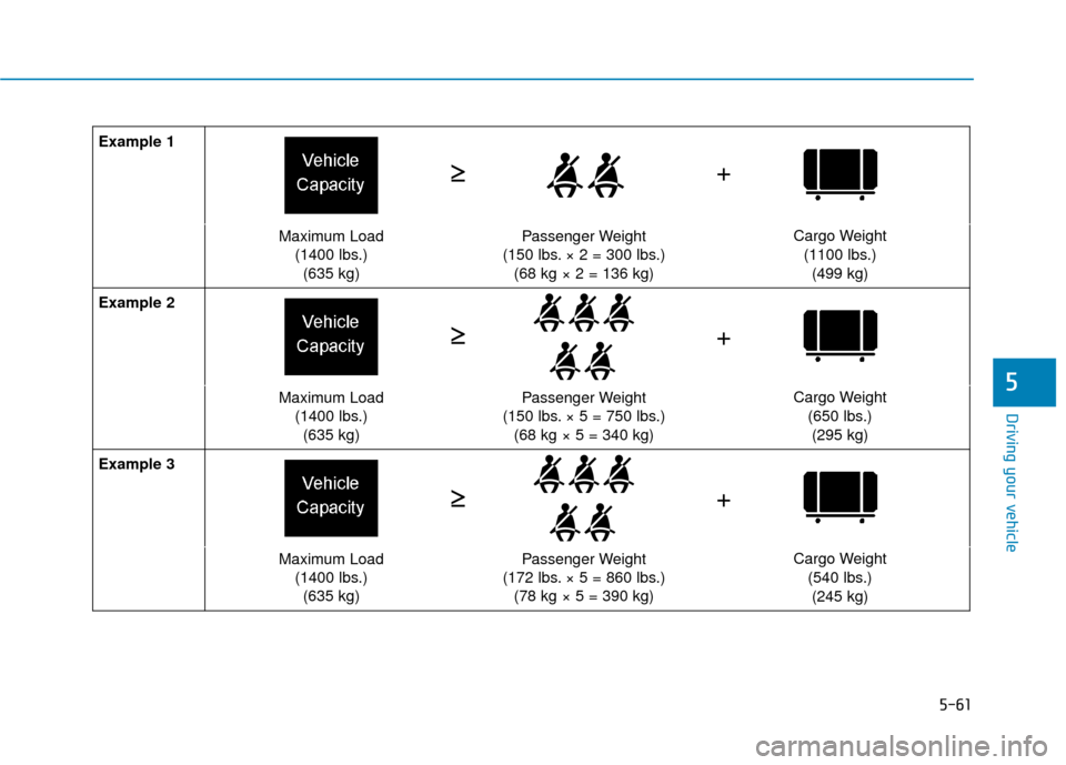
gage load capacity. For example, if
the "XXX" amount equals 1400
lbs. and there will be five 150 lb.
passengers in your vehicle, the
amount of available cargo and lug-
gage load capacity is 650 lbs.
(1400 - 750 (5 x 150) = 650 lbs.)
5. Determine the combined weight of luggage and cargo being loaded
on the vehicle. That weight may
not safely exceed the available
cargo and luggage load capacity
calculated in Step 4. 6. If your vehicle will be towing a trail-
er, load from your trailer will be
transferred to your vehicle. Consult
this manual to determine how this
reduces the available cargo and
luggage load capacity of your vehi-
cle.
Do not overload the vehicle as
there is a limit to the total
weight, or load limit, including
occupants and cargo, the vehi-
cle can carry. Overloading can
shorten the life of the vehicle. If
the GVWR or the GAWR is
exceeded, parts on the vehicle
can break, and it can change
the handling of your vehicle.
These could cause you to lose
control and result in an acci-
dent.
WARNING
Page 313 of 442

5-61
Driving your vehicle
5
Example 1
Maximum Load(1400 lbs.)(635 kg)Passenger Weight
(150 lbs. × 2 = 300 lbs.) (68 kg × 2 = 136 kg)Cargo Weight
(1100 lbs.)(499 kg)
Example 2
Maximum Load (1400 lbs.)(635 kg)Passenger Weight
(150 lbs. × 5 = 750 lbs.) (68 kg × 5 = 340 kg)Cargo Weight
(650 lbs.)(295 kg)
Example 3
Maximum Load (1400 lbs.)(635 kg)Passenger Weight
(172 lbs. × 5 = 860 lbs.) (78 kg × 5 = 390 kg)Cargo Weight
(540 lbs.)(245 kg)
+
≥
≥
≥ ≥
≥ ≥ +
+
Page 320 of 442

6-5
What to do in an emergency
6
Information
An inappropriately disposedbattery can be harmful to the
environment and human
health. Dispose of the battery
according to your local law(s)
or regulations.
To prevent damage to your vehicle:
Only use a 12-volt power supply (battery or jumper system) to
jump start your vehicle.
Do not attempt to jump start your vehicle by push-starting.
Jump starting procedure
1. Position the vehicles close enough that the jumper cables will reach,
but do not allow the vehicles to
touch.
2. Avoid fans or any moving parts in the engine compartment at all
times, even when the vehicles are
turned off.
3. Turn off all electrical devices such as radios, lights, air conditioning,
etc. Put the vehicles in P (Park)
and set the parking brakes. Turn
both vehicles OFF. 4. Connect the jumper cables in the
exact sequence shown in the illus-
tration. First connect one jumper
cable to the red, positive (+)
jumper terminal of your vehicle
(1).
5. Connect the other end of the jumper cable to the red, positive
(+) battery/jumper terminal of the
assisting vehicle (2).
6. Connect the second jumper cable to the black, negative (-) battery/
chassis ground of the assisting
vehicle (3).
NOTICE
i
Pb
(Continued)
NEVER attempt to recharge
the battery when the vehicle's
battery cables are connected
to the battery.
The electrical ignition system
works with high voltage.
NEVER touch these compo-
nents with the engine running
or when the ignition switch is
in the ON position.
1VQA4001
Page 329 of 442

6-14
What to do in an emergency
Jack and Tools
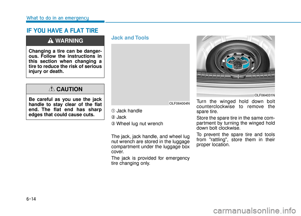
➀Jack handle
② Jack
③ Wheel lug nut wrench
The jack, jack handle, and wheel lug
nut wrench are stored in the luggage
compartment under the luggage box
cover.
The jack is provided for emergency
tire changing only. Turn the winged hold down bolt
counterclockwise to remove the
spare tire.
Store the spare tire in the same com-
partment by turning the winged hold
down bolt clockwise.
To prevent the spare tire and tools
from "rattling", store them in their
proper location.
I I
F
F
Y
Y O
O U
U
H
H A
AV
VE
E
A
A
F
F L
LA
A T
T
T
T I
IR
R E
E
Changing a tire can be danger-
ous. Follow the instructions in
this section when changing a
tire to reduce the risk of serious
injury or death.
WARNING
OLF064004N
OLF064031NBe careful as you use the jack
handle to stay clear of the flat
end. The flat end has sharp
edges that could cause cuts.
CAUTION
Page 330 of 442

6-15
What to do in an emergency
6
If it is hard to loosen the tire hold-
down wing bolt by hand, you can
loosen it easily using the jack handle.
1. Put the jack handle (1) inside ofthe tire hold-down wing bolt.
2. Turn the tire hold-down wing bolt counterclockwise with the jack
handle.
Changing Tires
Follow these steps to change your
vehicle's tire:
1. Park on a level, firm surface.
2. Move the shift lever into P (Park)or into R (Reverse) if equipped
with a manual transmission, apply
the parking brake, and place the
ignition switch in the LOCK/OFF
position.
3. Press the hazard warning flasher button.
4. Remove the wheel lug nut wrench, jack, jack handle, and spare tire
from the vehicle.
A vehicle can slip or roll off of a
jack causing serious injury or
death to you or those nearby.
Take the following safety pre-
cautions:
Never place any portion of
your body under a vehicle that
is supported by a jack.
NEVER attempt to change a
tire in the lane of traffic.
ALWAYS move the vehicle
completely off the road on
level, firm ground away from
traffic before trying to change
a tire. If you cannot find a level,
firm place off the road, call a
towing service for assistance.
Be sure to use the jack pro-
vided with the vehicle.
ALWAYS place the jack on the
designated jacking positions
on the vehicle and NEVER on
the bumpers or any other part
of the vehicle for jacking sup-
port.
(Continued)
(Continued)
Do not start or run the engine
while the vehicle is on the
jack.
Do not allow anyone to remain
in the vehicle while it is on the
jack.
Keep children away from the
road and the vehicle.
WARNING
OLF064005
Page 433 of 442

8-11
88
Specifications, Consumer information and Reporting safety defects
Eastern Region:
Connecticut, Delaware,
Maine, Massachusetts, New
Hampshire, New Jersey, New York,
Pennsylvania, Rhode Island,
Vermont.
Eastern Region
1122 Cranbury South River Road
Jamesburg, NJ 08831
(800) 633-5151
Southern Region:
Florida, Georgia, Maryland, North
Carolina, South Carolina, Virginia,
West Virginia.
Southern Region
3025 Chastain Meadows Parkway
Suite 100 Marietta, GA 30066
(800) 633-5151South Central Region:
Alabama, Arkansas, Louisiana,
Mississippi, New Mexico, Oklahoma,
Tennessee, Texas.
South Central Region
1421 South Beltline Road, Suite 400
Coppell, TX 75019
(800) 633-5151
Central Region:
Illinois, Indiana, lowa, Kentucky,
Michigan, Minnesota, Nebraska,
North Dakota, South Dakota, Ohio,
Wisconsin, Kansas, Missouri.
Central Region
2 Trans Am Plaza Dr #500 Oakbrook
Terrace, IL 60181
(800) 633-5151Western Region:
Alaska, Hawaii, Arizona, California,
Colorado, Idaho, Montana, Nevada,
Oregon, Utah, Washington,
Wyoming.
Western Region
10550 Talbert Avenue P.O.Box
20850 Fountain Valley, California
92728-0850
(800) 633-5151
C C
O
O N
NS
SU
U M
M E
ER
R
I
IN
N F
FO
O R
RM
M A
AT
TI
IO
O N
N
This consumer information has been prepared in accordance with regulations issued by the National Highway Traffic
Safety Administration of the U.S. Department of Transportation. Your HYUNDAI dealer will help answer any questions you
may have as you read this information.
HYUNDAI motor vehicles are designed and manufactured to meet or exceed all applicable safety standards.
For your safety, however, we strongly urge you to read and follow all directions in this Owner’s Manual, particularly the
information under the headings "NOTICE", "CAUTION" and "WARNING".
If, after reading this manual, you have any questions regarding the operation of your vehicle, please contact your nearest
HYUNDAI Motor America Regional Office as listed in the following: