2018 HONDA RIDGELINE height
[x] Cancel search: heightPage 171 of 623

169
uuAdjusting the Seats uHead Restraints
Controls
A passenger sitting in the rear seating position
should adjust the height of their head restraint
to an appropriate position before the vehicle
begins moving.
To raise the head restraint:
Pull it upward.
To lower the head restraint:
Push it down while pressing the release
button.
Head restraints can be removed for cleaning or repair.
To remove a head restraint:
Pull the restraint up as far as it will go. Then push the release button, and pull the
restraint up and out.
To reinstall a head restraint:
Insert the legs back in place, then adjust the head restraint to an appropriate height
while pressing the release button. Pull up on the restraint to make sure it is locked
in position.
■Changing the Rear Seat Head Restraint Position
■Removing and Reinstalling the Head Restraints1 Removing and Reinstalling the Head Restraints
3WARNING
Failure to reinstall, or correctly reinstall, the
head restraints can result in severe injury
during a crash.
Always replace the he ad restraints before
driving.
Page 413 of 623

Continued411
uuBefore Driving uDriving Preparation
Driving
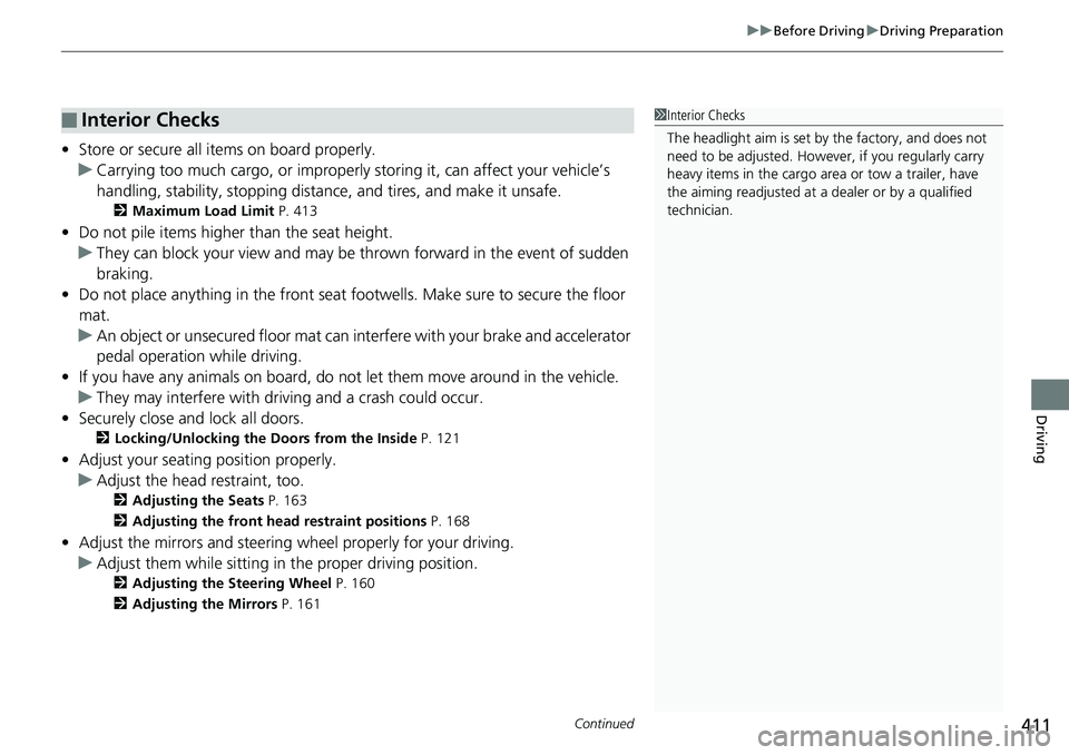
• Store or secure all items on board properly.
u Carrying too much cargo, or improperly storing it, can affect your vehicle’s
handling, stability, sto pping distance, and tires, and make it unsafe.
2Maximum Load Limit P. 413
•Do not pile items higher than the seat height.
u They can block your view and may be thrown forward in the event of sudden
braking.
• Do not place anything in the front seat footwells. Make sure to secure the floor
mat.
u An object or unsecured floor mat can in terfere with your brake and accelerator
pedal operation while driving.
• If you have any animals on board, do no t let them move around in the vehicle.
u They may interfere with driv ing and a crash could occur.
• Securely close and lock all doors.
2Locking/Unlocking the Doors from the Inside P. 121
•Adjust your seating position properly.
u Adjust the head restraint, too.
2Adjusting the Seats P. 163
2 Adjusting the front head restraint positions P. 168
•Adjust the mirrors and steering wh eel properly for your driving.
u Adjust them while sitting in the proper driving position.
2 Adjusting the Steering Wheel P. 160
2 Adjusting the Mirrors P. 161
■Interior Checks1Interior Checks
The headlight aim is set by the factory, and does not
need to be adjusted. Howeve r, if you regularly carry
heavy items in the cargo area or tow a trailer, have
the aiming readjusted at a dealer or by a qualified
technician.
Page 422 of 623

420
uuTowing a Trailer uTowing Preparation
Driving
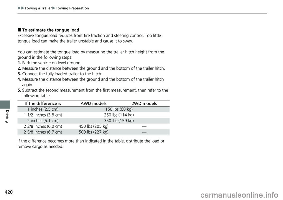
■To estimate the tongue load
Excessive tongue load reduces front tire traction and steering control. Too little
tongue load can make the trailer unstable and cause it to sway.
You can estimate the tongue load by meas uring the trailer hitch height from the
ground in the following steps:
1. Park the vehicle on level ground.
2. Measure the distance between the ground and the bottom of the trailer hitch.
3. Connect the fully loaded trailer to the hitch.
4. Measure the distance between the ground and the bottom of the trailer hitch
again.
5. Subtract the second measurement from th e first measurement, then refer to the
following table.
If the difference becomes more than indicated in the table, distribute the load or
remove cargo as needed.
If the difference isAWD models2WD models
1 inches (2.5 cm)150 lbs (68 kg)
1 1/2 inches (3.8 cm)250 lbs (114 kg)
2 inches (5.1 cm)350 lbs (159 kg)
2 3/8 inches (6.0 cm)450 lbs (205 kg)—
2 5/8 inches (6.7 cm)500 lbs (227 kg)—
Page 424 of 623

uuTowing a Trailer uTowing Preparation
422
Driving
Towing generally requires a variety of supplemental equipment.
To ensure the best quality, we recommend that you purchase Honda equipment
whenever possible.
Your vehicle has a class 3 trailer hitch as standard equipment. The jumper harness
and trailer brake fuse are stored in the glove box.
2 Trailer brakes P. 423
Open the lid of the socket (located next to the
trailer hitch) to expose the 7-pin trailer
connector.
■Hitches
Read the trailer manufacturer’s instructions , and select the appropriate draw bar for
the height of the trailer you will be towing.
■Towing Equipment and Accessories
Models with AWD1 Towing Equipment and Accessories
Make sure that all equipment is properly installed and
maintained, and that it meets federal, state, province/
territory, and lo cal regulations.
Consult your trai ler maker for prope r installation and
setup of the equipment.
Improper installation and setup can affect the
handling, stability, and br aking performance of your
vehicle.
Consult your traile r sales or rental agency if any other
items are recommended or required for your towing
situation.
The lighting and wiring of tra ilers can vary by type
and brand. If a connector is required, it should only
be installed by a qua lified technician.
Trailer packages and products:
•Ball mount, hitch plug, hitch pin etc.•Wiring harness kit
•Trailer hitch kit (jum per harness included)
Are available at a dealer.
7-Pin trailer connector
Lid Trailer hitch
Page 488 of 623

486
uuWhen Driving uLaneWatchTM*
Driving
LaneWatchTM*
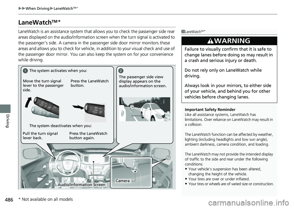
LaneWatch is an assistance system that allows you to check the passenger side rear
areas displayed on the audio/information scr een when the turn signal is activated to
the passenger’s side. A camera in the pass enger side door mirror monitors these
areas and allows you to check for vehicle, in addition to your visual check and use of
the passenger door mirror. You can also keep the system on for your convenience
while driving.1 LaneWatchTM*
Important Safety Reminder
Like all assistance systems, LaneWatch has
limitations. Over reliance on LaneWatch may result in
a collision.
The LaneWatch func tion can be affected by weather,
lighting (including headli ghts and low sun angle),
ambient darkness, camera condition, and loading.
The LaneWatch may not prov ide the intended display
of traffic to the side and rear under the following
conditions:
•Your vehicle’s suspension has been altered,
changing the height of the vehicle.
•Your tires are over or under inflated.
•Your tires or wheels are of varied size or construction.
3WARNING
Failure to visually confirm that it is safe to
change lanes before doing so may result in
a crash and serious injury or death.
Do not rely only on LaneWatch while
driving.
Always look in your mirrors, to either side
of your vehicle, and behind you for other
vehicles before changing lanes.
12
CameraAudio/Information Screen
Move the turn signal
lever to the passenger
side.
Press the LaneWatch
button.
Pull the turn signal
lever back. Press the LaneWatch
button again. The passenger side view
display appears on the
audio/information screen.
The system activates when you:
The system deactivates when you:
* Not available on all models
Page 528 of 623

526
uuMaintenance Under the Hood uOpening the Hood
Maintenance
Opening the Hood
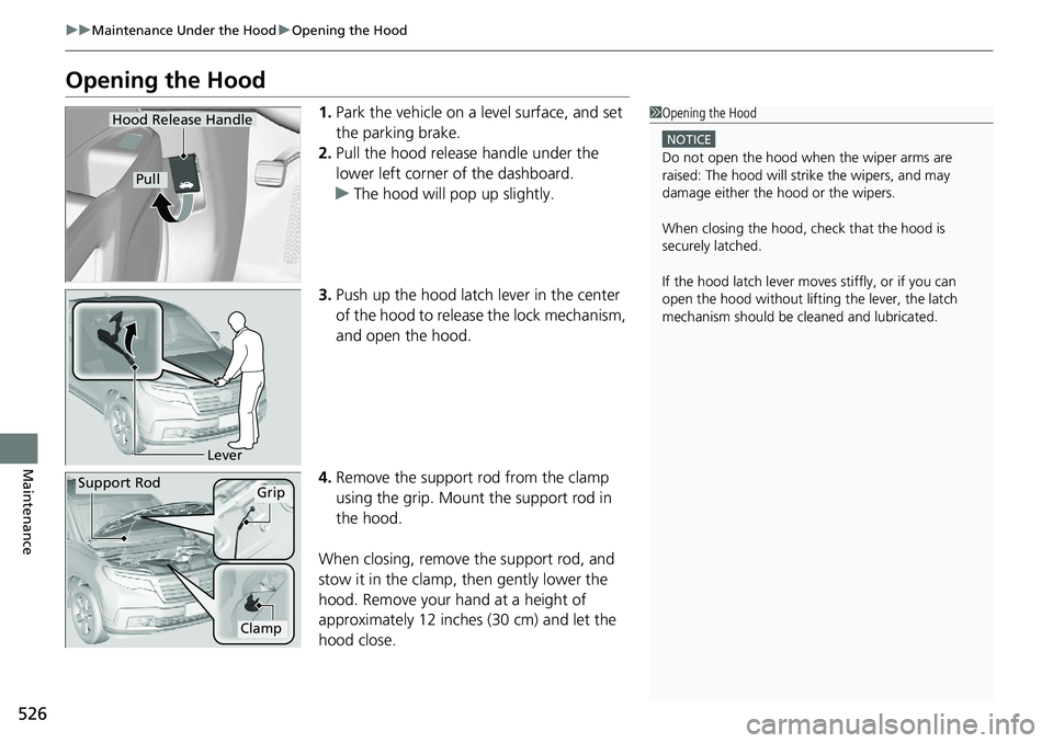
1. Park the vehicle on a level surface, and set
the parking brake.
2. Pull the hood release handle under the
lower left corner of the dashboard.
u The hood will pop up slightly.
3. Push up the hood latch lever in the center
of the hood to release the lock mechanism,
and open the hood.
4. Remove the support rod from the clamp
using the grip. Mount the support rod in
the hood.
When closing, remove the support rod, and
stow it in the clamp, then gently lower the
hood. Remove your hand at a height of
approximately 12 inches (30 cm) and let the
hood close.1 Opening the Hood
NOTICE
Do not open the hood when the wiper arms are
raised: The hood will stri ke the wipers, and may
damage either the hood or the wipers.
When closing the hood, check that the hood is
securely latched.
If the hood latch lever moves stiffly, or if you can
open the hood without lifti ng the lever, the latch
mechanism should be cleaned and lubricated.
Hood Release Handle
Pull
Lever
Support RodGrip
Clamp
Page 548 of 623

546
uuChecking and Maintaining Tires uTire and Loading Information Label
Maintenance
Tire and Loading Information Label
The label attached to the driver’s doorj amb provides necessary tire and loading
information.
Tire Labeling
The tires that came on your vehicle have a
number of markings. Those you should be
aware of are described below.
Whenever tires are replaced, they should be replaced with tires of the same size.
1 Tire and Loading Information Label
The tire and loading informat ion label attached to the
driver’s doorjamb contains:
aThe number of people your vehicle can carry.
bThe total weight your vehicle can carry. Do not
exceed this weight.
cThe original tire sizes for front, rear, and spare.
dThe proper cold tire pressure for front, rear, and
spare.
Label
Example
Example Tire Size
Tire
Identification
Number (TIN)
Maximum
Tire Load
Maximum
Tire Pressure
Tire Size
■Tire Sizes
1 Tire Sizes
Following is an example of tire size with an
explanation of what each component means.
P235/60R18 102V
P: Vehicle type (P indi cates passenger vehicle).
235: Tire width in millimeters.
60: Aspect ratio (the tire’s section height as a
percentage of its width).
R: Tire construction code (R indicates radial).
18: Rim diameter in inches.
102: Load index (a numerical code associated with
the maximum load the tire can carry).
V: Speed symbol (an alphab etical code indicating the
maximum speed rating).