2018 HONDA HR-V fuses
[x] Cancel search: fusesPage 4 of 503

Contents
This owner’s manual should be considered a permanent part of the
vehicle and should remain with the vehicle when it is sold.
This owner’s manual covers all models of your vehicle. You may find
descriptions of equipment and features that are not on your
particular model.
Images throughout this owner’s manual (including the front cover)
represent features and equipment that are available on some, but
not all, models. Your particular mo del may not have some of these
features.
This owner’s manual is for vehicles sold in the United States and
Canada.
The information and specifications in cluded in this publication were
in effect at the time of approval for printing. Honda Motor Co., Ltd.
reserves the right, however, to discontinue or change specifications
or design at any time without notice and without incurring any
obligation.2 Safe Driving P. 29
For Safe Driving P. 30 Seat Belts P. 35 Airbags P. 44
2Instrument Panel P. 73
Indicators P. 74 Gauges and Displays P. 90
2Controls P. 95
Clock P. 96 Locking and Unlocking the Doors P. 98
Opening and Closing the Windows P. 121
Operating the Switches Around the Steering Wheel P. 124
Interior Lights/Interior Convenience Items P. 152
2 Features P. 177
Audio System P. 178 Audio System Basic Operation P. 184, 205
Customized Features P. 252 Bluetooth® HandsFreeLink ® P. 274, 297
2 Driving P. 327
Before Driving P. 328 Towing a Trailer P. 333
Parking Your Vehicle P. 385 Multi-View Rear Camera P. 386
2Maintenance P. 391
Before Performing Maintenance P. 392 Maintenance MinderTM P. 395
Checking and Maintaining Wiper Blades P. 419
Heating and Cooling System
*/Climate Control System* Maintenance P. 437
2 Handling the Unexpected P. 445
Tools P. 446 If a Tire Goes Flat P. 448
Overheating P. 463 Indicator, Coming On/Blinking P. 465 Fuses P. 470
2 Information P. 479
Specifications P. 480 Identification Numbers P. 482
Emissions Testing P. 485 Warranty Coverages P. 487
18 HR-V-31T7A6200.book 2 ページ 2017年6月30日 金曜日 午後1時23分
Page 337 of 503

Continued335
uuTowing a Trailer uTowing Your Vehicle
Driving
■Extended towing
If you tow more than eight hours in one day, you should repeat the “When Your
Vehicle is Towed Behind a Motorhome” at least every eight hours.
You also need to perform the following procedure to prevent the battery from
running down.
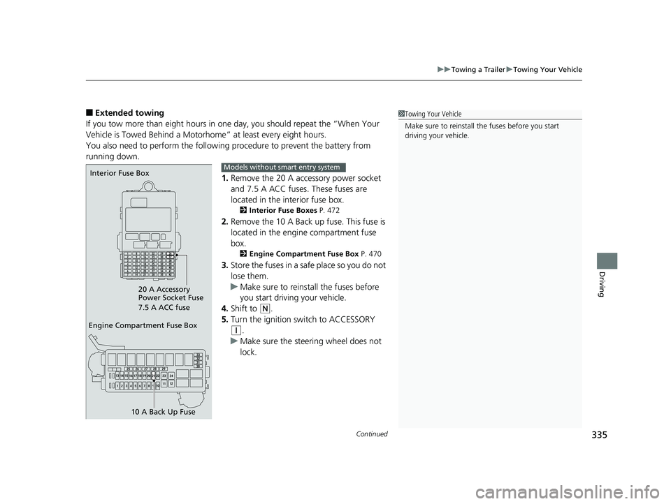
1.Remove the 20 A accessory power socket
and 7.5 A ACC fuses. These fuses are
located in the interior fuse box.
2 Interior Fuse Boxes P. 472
2.Remove the 10 A Back up fuse. This fuse is
located in the engine compartment fuse
box.
2 Engine Compartment Fuse Box P. 470
3.Store the fuses in a safe place so you do not
lose them.
u Make sure to reinstall the fuses before
you start driving your vehicle.
4. Shift to
(N.
5. Turn the ignition switch to ACCESSORY
(q.
u Make sure the steering wheel does not
lock.
1Towing Your Vehicle
Make sure to reinstall th e fuses before you start
driving your vehicle.
Engine Compartment Fuse Box
10 A Back Up Fuse
Interior Fuse Box
20 A Accessory
Power Socket Fuse
7.5 A ACC fuseModels without smart entry system
18 HR-V-31T7A6200.book 335 ページ 2017年6月30日 金曜日 午後1時23分
Page 338 of 503

336
uuTowing a Trailer uTowing Your Vehicle
Driving
1. Remove the 20 A accessory power socket and 7. 5 A ACC fuses. These fuses are located in the
interior fuse box.
2 Interior Fuse Boxes P. 472
2.Remove the 10 A Back up fuse. This fuse is located in the engine compartment fuse box.
2Engine Compartment Fuse Box P. 4703.Store the fuses in a safe place so you do not lose them.
u Make sure to reinstall the fuses be fore you start driving your vehicle.
4. Push the ENGINE START/STOP button without depressing the clutch pedal.
u The indicator on the ENGINE START/STOP button blinks.
5. Touch the center of the ENGINE START/STOP button with the H logo on the smart entry remote
while the indicator is blinking.
u The indicator stop blinking, then stays on.
6. Shift to
(N.
7. Push the ENGINE START/STOP button once without depressing the clutch pedal.
u Make sure the steering wheel does not lock.
Engine Compartment Fuse Box
10 A Back Up Fuse
Interior Fuse Box
20 A Accessory
Power Socket Fuse
7.5 A ACC fuseModels with smart entry system
18 HR-V-31T7A6200.book 336 ページ 2017年6月30日 金曜日 午後1時23分
Page 445 of 503

443
Maintenance
Accessories and Modifications
Accessories
When installing accessories, check the following:
• Do not install accessories on the windsh ield. They can obstruct your view and
delay your reaction to driving conditions.
• Do not install any accessories over areas marked SRS AIRBAG, on the sides or
backs of the front seats, on front or si de pillars, or near the side windows.
Accessories installed in these areas may interfere with proper operation of the
vehicle’s airbags or may be propelled into you or another occupant if the airbags
deploy.
• Be sure electronic accessories do not overload electrical circuits or interfere with
proper operation of your vehicle.
2 Fuses P. 470
•Before installing any electro nic accessory, have the installer contact a dealer for
assistance. If possible, have a deal er inspect the final installation.
1Accessories and Modifications
Honda Genuine accessor ies are recommended to
ensure proper operati on on your vehicle.
3WARNING
Improper accessories or modifications can
affect your vehicle’s handling, stability, and
performance, and cause a crash in which
you can be seriously hurt or killed.
Follow all instruction s in this owner’s
manual regarding accessories and
modifications.
18 HR-V-31T7A6200.book 443 ページ 2017年6月30日 金曜日 午後1時23分
Page 447 of 503

445
Handling the Unexpected
This chapter explains how to handle unexpected troubles.
ToolsTypes of Tools .................................. 446
If a Tire Goes Flat Changing a Flat Tire ......................... 448
Engine Does Not Start Checking the Engine ........................ 457
If the Smart Entry Remote Battery is Weak ....458
Emergency Engine Stop ................... 459
Jump Starting .................................... 460
Shift Lever Does Not Move .............. 462
Overheating How to Handle Overheating ............. 463 Indicator, Coming On/Blinking
If the Low Oil Pressure Indicator Comes
On ............................................. 465
If the Charging System Indicator Comes
On ................................................. 465
If the Malfunction Indicator Lamp Comes On or Blinks ..................................... 466
If the Brake System Indicator (Red) Comes On...................................................... 467
If the Electric Power Steering (EPS) System Indicator Comes On ....................... 467 If the Electric Parking Brake System
Indicator Comes On ....................... 468
If the Low Tire Pressure/TPMS Indicator Comes On or Blinks ....................... 469
Fuses Fuse Locations ................................. 470
Inspecting and Changing Fuses ........ 474
Emergency Towing ........................... 475
When You Cannot Open the Tailgate..... 476
18 HR-V-31T7A6200.book 445 ページ 2017年6月30日 金曜日 午後1時23分
Page 459 of 503

457
Handling the Unexpected
Engine Does Not Start
Checking the Engine
If the engine does not start, check the starter.
Starter conditionChecklist
Starter doesn’t turn or turns
over slowly.
The battery may be dead. Check
each of the items on the right and
respond accordingly.Check the brightness of the interior lights.
Turn on the interior lights and check the brightness.
●If the interior lights are dim or do not come on at all
2Battery P. 433●If the interior lights come on normally 2 Fuses P. 470
The starter turns over normally
but the engine doesn’t start.
There may be a problem with the
fuse. Check each of the items on
the right and respond accordingly.Review the engine start procedure.
Follow its instructions, and try to start the engine again.
2 Starting the Engine P. 339, 342
Check the immobilize r system indicator.
When the immobilizer system indicator is blinking, the engine cannot be started.
2 Immobilizer System P. 118
Check the fuel level.
There should be enough fuel in the tank.
2 Fuel Gauge P. 93
Check the fuse.
Check all fuses, or have your vehicle checked by a dealer.
2Inspecting and Changing Fuses P. 474
If the problem continues:
2Emergency Towing P. 475
1Checking the Engine
If you must start the vehi cle immediately, use an
assisting vehicle to jump start it.
2 Jump Starting P. 460
18 HR-V-31T7A6200.book 457 ページ 2017年6月30日 金曜日 午後1時23分
Page 472 of 503

470
Handling the Unexpected
Fuses
Fuse Locations
If any electrical devices are not working,
turn the ignition switch to LOCK
(0*1 and
check to see if any appl icable fuse is blown.
■Fuse box A
Located near the brake fluid reservoir. Push
the tabs to open the box.
Fuse locations are shown on the fuse box
cover. Locate the fuse in question by the
fuse number and box cover number.
■Engine Compartment Fuse Box
Tab
■Circuit protected and fuse rating
Circuit ProtectedAmps
1Headlight Low Beam Main20 A
2CDC*(30 A)
3Hazard10 A
4DBW15 A
5Wiper*(30 A)
6Stop10 A
7IGP15 A
8IG Coil15 A
9EOP*(10 A)
10INJ*(20 A)
11VST2*(30 A)
12Main Fan30 A
13Starter SW*(30 A)
14MG Clutch7.5 A
15Battery Sensor(7.5 A)
16Small Light10 A
17AFP Main*(10 A)
18Horn10 A
19Fog Light*(10 A)
20SBW*(10 A)
*1:Models with the sma rt entry system have
an ENGINE START/STOP button
instead of an ignition switch.
Circuit ProtectedAmps
21Back Up Main10 A
22Audio(10 A)
23Sub Fan(30 A)
24VST1*(30 A)
25STRLD*(7.5 A)
26IGP CAM*(7.5 A)
27––
28––
29Back Up*(30 A)
30IGP LAF(7.5 A)
31IGPS(7.5 A)
32Right Headlight Low Beam10 A
33Left Headlight Low Beam10 A
* Not available on all models
18 HR-V-31T7A6200.book 470 ページ 2017年6月30日 金曜日 午後1時23分
Page 473 of 503

471
uuFuses uFuse Locations
Continued
Handling the Unexpected
■Fuse box B
Tab
a
bcd
Pull up the cover on the + terminal, then
remove it while pulling out the tab as
shown.
Replacement of engine compartment fuses
should be done by a dealer.■Circuit protected and fuse rating
Circuit ProtectedAmps
aBattery Main100 A
bRB Main 170 A
cRB Main 280 A
dCAP Main70 A
18 HR-V-31T7A6200.book 471 ページ 2017年6月30日 金曜日 午後1時23分