2018 HONDA CLARITY ELECTRIC stop start
[x] Cancel search: stop startPage 423 of 559
Continued421
uuBraking uBrake System
Driving
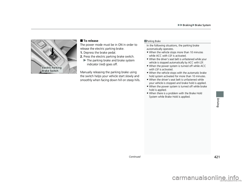
■To release
The power mode must be in ON in order to
release the electric parking brake.
1. Depress the brake pedal.
2. Press the electric parking brake switch.
u The parking brake and brake system
indicator (red) goes off.
Manually releasing the parking brake using
the switch helps your vehicle start slowly and
smoothly when facing down hill on steep hills.1 Parking Brake
In the following situations, the parking brake
automatically operates.
•When the vehicle stops more than 10 minutes
while ACC with LSF is activated.
•When the driver’s seat belt is unfastened while your
vehicle is stopped automatically by ACC with LSF.
•When the power system is turned off while ACC
with LSF is activated.
•When the vehicle stops with the automatic brake
hold system activated for more than 10 minutes.
•When the driver’s seat belt is unfastened while
your vehicle is stopped and brake hold is applied.
•When the power system is turned off while brake
hold is applied.
•When there is a problem with the Brake Hold
System while Brake Hold is applied.
Electric Parking
Brake Switch
18 CLARITY ELECTRIC CSS-31TRV6100.book 421 ページ 2018年2月5日 月曜日 午後12時0分
Page 426 of 559
uuBraking uBrake System
424
Driving
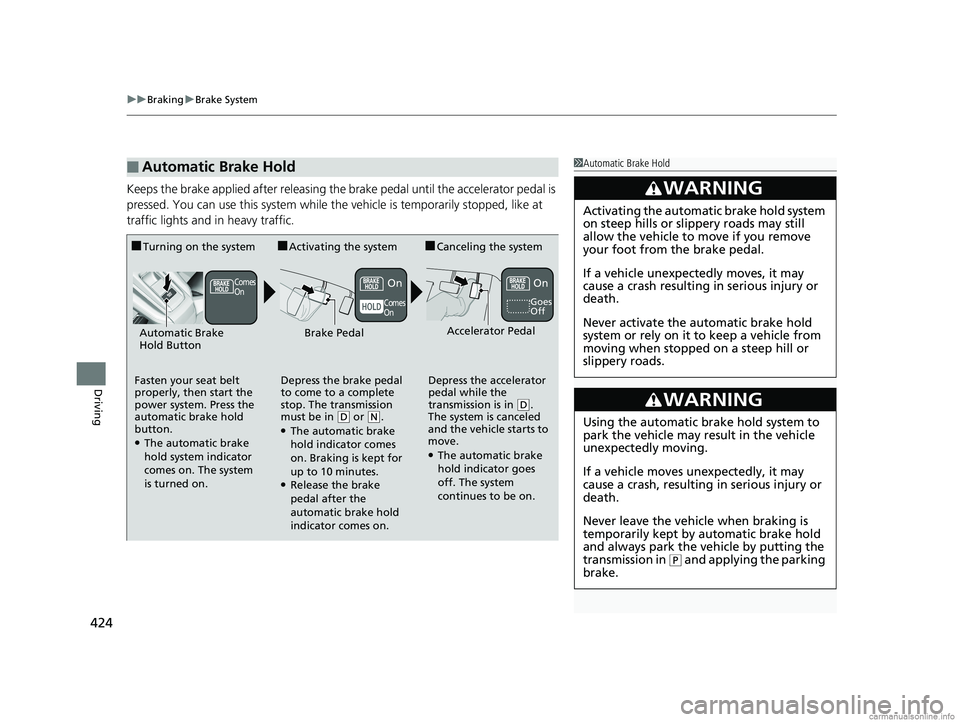
Keeps the brake applied after releasing the brake pedal until the accelerator pedal is
pressed. You can use this system while the vehicle is temporarily stopped, like at
traffic lights and in heavy traffic.
■Automatic Brake Hold1Automatic Brake Hold
3WARNING
Activating the automatic brake hold system
on steep hills or slippery roads may still
allow the vehicle to move if you remove
your foot from the brake pedal.
If a vehicle unexpectedly moves, it may
cause a crash resulting in serious injury or
death.
Never activate the automatic brake hold
system or rely on it to keep a vehicle from
moving when stopped on a steep hill or
slippery roads.
3WARNING
Using the automatic brake hold system to
park the vehicle may result in the vehicle
unexpectedly moving.
If a vehicle moves unexpectedly, it may
cause a crash, resulting in serious injury or
death.
Never leave the vehicle when braking is
temporarily kept by automatic brake hold
and always park the vehicle by putting the
transmission in
( P and applying the parking
brake.
■Turning on the system
Fasten your seat belt
properly, then start the
power system. Press the
automatic brake hold
button.
●The automatic brake
hold system indicator
comes on. The system
is turned on.
■Activating the system
Depress the brake pedal
to come to a complete
stop. The transmission
must be in
( D or (N.●The automatic brake
hold indicator comes
on. Braking is kept for
up to 10 minutes.
●Release the brake
pedal after the
automatic brake hold
indicator comes on.
■Canceling the system
Depress the accelerator
pedal while the
transmission is in
( D.
The system is canceled
and the vehicle starts to
move.
●The automatic brake
hold indicator goes
off. The system
continues to be on.
Accelerator PedalBrake PedalAutomatic Brake
Hold Button
Goes
Off
Comes
On
Comes
OnOnOn
18 CLARITY ELECTRIC CSS-31TRV6100.book 424 ページ 2018年2月5日 月曜日 午後12時0分
Page 430 of 559
428
uuBraking uCollision Mitigation Braking SystemTM (CMBSTM)
Driving
Collision Mitigati on Braking SystemTM (CMBSTM)
Can assist you when there is a possibility of your vehicle colliding with a vehicle or a
pedestrian detected in front of yours. The CMBSTM is designed to alert you when a
potential collision is determined, as well as to reduce your vehicle speed to help
minimize collision severity when a collision is deemed unavoidable.
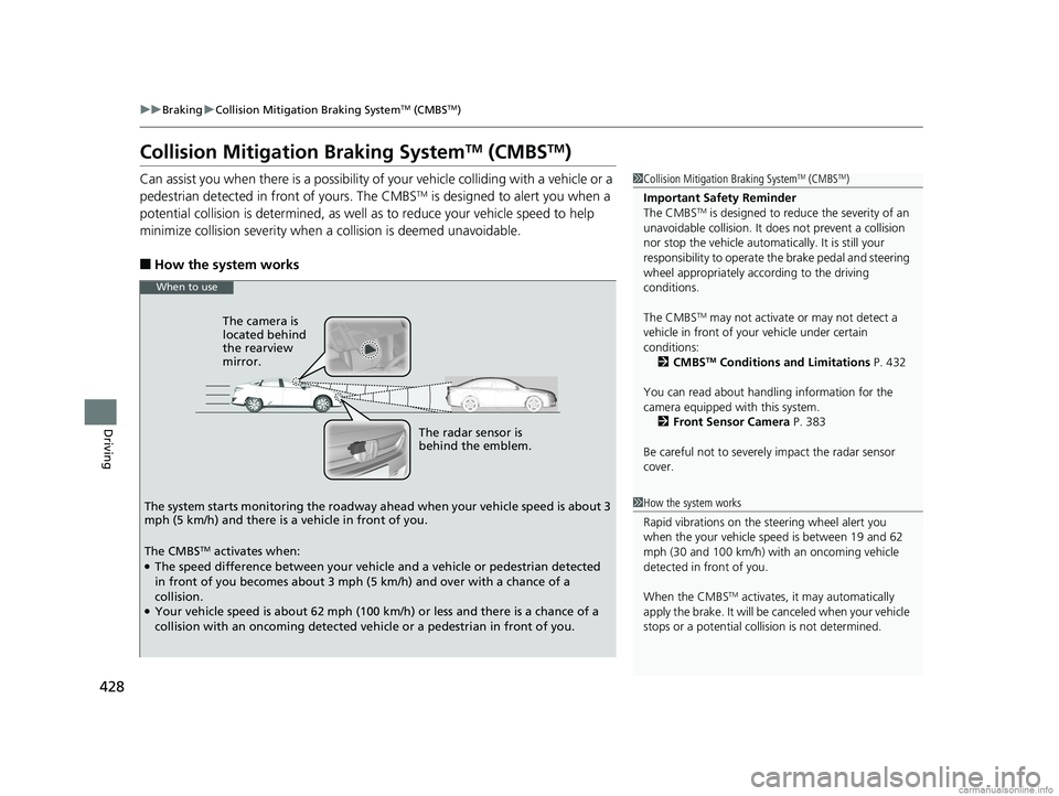
■How the system works
1 Collision Mitigation Braking SystemTM (CMBSTM)
Important Safety Reminder
The CMBS
TM is designed to reduce the severity of an
unavoidable collision. It do es not prevent a collision
nor stop the vehicle automati cally. It is still your
responsibility to operate the brake pedal and steering
wheel appropriately acco rding to the driving
conditions.
The CMBS
TM may not activate or may not detect a
vehicle in front of y our vehicle under certain
conditions: 2 CMBS
TM Conditions and Limitations P. 432
You can read about handling information for the
camera equipped with this system. 2 Front Sensor Camera P. 383
Be careful not to severely impact the radar sensor
cover.
1 How the system works
Rapid vibrations on the steering wheel alert you
when the your vehicle speed is between 19 and 62
mph (30 and 100 km/h) with an oncoming vehicle
detected in front of you.
When the CMBS
TM activates, it may automatically
apply the brake. It will be canceled when your vehicle
stops or a potential coll ision is not determined.
The radar sensor is
behind the emblem.
The camera is
located behind
the rearview
mirror.
The system starts monitoring the roadway ah ead when your vehicle speed is about 3
mph (5 km/h) and there is a vehicle in front of you.
When to use
The CMBSTM activates when:●The speed difference between your vehicle and a vehicle or pedestrian detected
in front of you becomes about 3 mph (5 km/h) and over with a chance of a
collision.
●Your vehicle speed is about 62 mph (100 km/h) or less and there is a chance of a
collision with an oncoming detected vehicle or a pedestrian in front of you.
18 CLARITY ELECTRIC CSS-31TRV6100.book 428 ページ 2018年2月5日 月曜日 午後12時0分
Page 445 of 559
Continued443
uuCharging uCharge the High Voltage battery using a Level 1, 2 or SAE J1772 DC charger
Driving
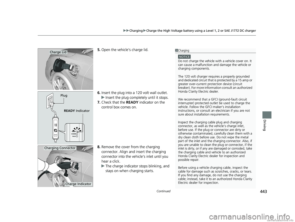
5. Open the vehicle’s charge lid.
6. Insert the plug into a 120 volt wall outlet.
u Insert the plug complete ly until it stops.
7. Check that the READY indicator on the
control box comes on.
8. Remove the cover from the charging
connector. Align and insert the charging
connector into the vehicle’s inlet until you
hear a click.
u The charge indicator stops blinking, and
stays on when charging starts.Charge Lid
Plug
READY Indicator
1Charging
NOTICE
Do not charge the vehicle wi th a vehicle cover on. It
can cause a malfunction and damage the vehicle or
charging components.
The 120 volt charger requires a properly grounded
and dedicated circuit that is protected by a 15 amp or
greater over-curre nt protection device (circuit
breaker). For more informati on consult an authorized
Honda Clarity Electric dealer.
We recommend that a GFCI (ground-fault circuit
interrupter) protected outlet be used to charge the
vehicle. Follow the GF CI maker's installation
instructions, or consult an electrician if you are not
sure about installation requirements.
Inspect the charging cable plug and charging
connector, as well as the vehicle’s charge inlet,
before use. If the plug or connector are dirty or
otherwise contaminated, care fully clean them with a
dry clean cloth before use. Do not wipe the metal
part of the inlet and the ch arging connector. Also, if
you are unable to clean the plug or connector, if the
inlet is dirty, or if any ar e damaged or corroded, take
the charging cable and vehi cle to an authorized
Honda Clarity Electric de aler for inspection and
possible repair.
Before using a vehicle char ging cable, inspect the
cable for damage such as scratches, cracks, or tears.
If you find any damage, do not use the charging
cable; instead, take it to an authorized Honda Clarity
Electric dealer for inspection.
Charging Connector
Charge Indicator
18 CLARITY ELECTRIC CSS-31TRV6100.book 443 ページ 2018年2月5日 月曜日 午後12時0分
Page 446 of 559
uuCharging uCharge the High Voltage battery using a Level 1, 2 or SAE J1772 DC charger
444
Driving
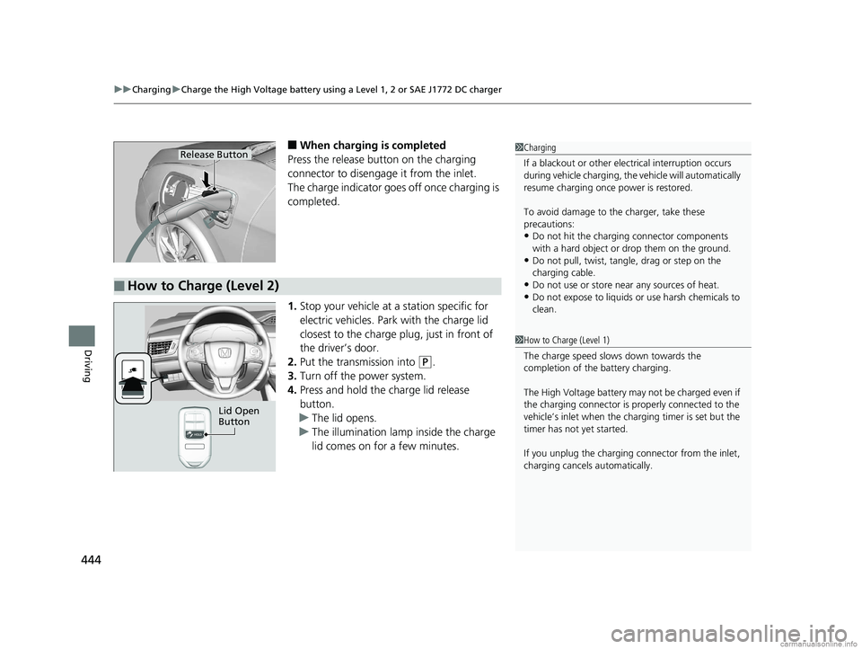
■When charging is completed
Press the release button on the charging
connector to disengage it from the inlet.
The charge indicator goes off once charging is
completed.
1. Stop your vehicle at a station specific for
electric vehicles. Park with the charge lid
closest to the charge plug, just in front of
the driver’s door.
2. Put the transmission into
(P.
3. Turn off the power system.
4. Press and hold the charge lid release
button.
u The lid opens.
u The illumination lamp inside the charge
lid comes on for a few minutes.
1Charging
If a blackout or other elec trical interruption occurs
during vehicle charging, the vehicle will automatically
resume charging once power is restored.
To avoid damage to th e charger, take these
precautions:
•Do not hit the charging connector components
with a hard object or drop them on the ground.
•Do not pull, twist, tangle, drag or step on the
charging cable.
•Do not use or store near any sources of heat.
•Do not expose to liquids or use harsh chemicals to
clean.
Release Button
■How to Charge (Level 2)
1How to Charge (Level 1)
The charge speed slows down towards the
completion of the battery charging.
The High Voltage battery may not be charged even if
the charging connector is properly connected to the
vehicle’s inlet when the charging timer is set but the
timer has not yet started.
If you unplug the charging connector from the inlet,
charging cancels automatically.
Lid Open
Button
18 CLARITY ELECTRIC CSS-31TRV6100.book 444 ページ 2018年2月5日 月曜日 午後12時0分
Page 515 of 559
513
uuPower System Won’t StartuEmergency Power System Off
Handling the Unexpected
Emergency Power System Off
The POWER button may be used to turn the power system off due to an emergency
situation even while driving. If you must tu rn the power system off, do either of the
following operations:
• Press and hold the POWER button for about two seconds.
• Firmly press the POWER button three times.
The steering wheel will not lock. However, because turning off the power system
disables the power assist the power syst em provides to the steering and braking
systems, it will require significantly more physical effort and time to steer and slow
the vehicle. Use both feet on the brake pe dal to slow down the vehicle and stop
immediately in a safe place.
The gear position auto matically changes to
(P after the vehicle comes to a complete
stop. Then, the power mode changes to VEHICLE OFF.
1 Emergency Power System Off
Do not press the button while driving unless it is
absolutely necessary for the power system to be
turned off.
18 CLARITY ELECTRIC CSS-31TRV6100.book 513 ページ 2018年2月5日 月曜日 午後12時0分
Page 520 of 559
518
Handling the Unexpected
Indicator, Coming On/Blinking
If the 12-Volt Battery Charging System Indicator
Comes On
■Reasons for the indicator to come on
Comes on when the 12-volt battery is not being charged.
■What to do when the indicator comes on
Turn off the climate con trol system, rear defogger, and other electrical
systems, and immediately contact an authorized Honda Clarity Electric
dealer for repairs.
1 If the 12-Volt Battery Chargi ng System Indicator Comes On
If you need to stop temporarily, do not turn off the
power system. Restarting the power system may
rapidly discharge the battery.
The power system uses the 12-volt battery to
activate.
You may not be able to turn the power system on
again if you have turned it off with this indicator on.
18 CLARITY ELECTRIC CSS-31TRV6100.book 518 ページ 2018年2月5日 月曜日 午後12時0分
Page 554 of 559
552
Index
Shift Button......................................... 31, 371Operation ................................................ 373
Shifting (Transmission) ....................... 31, 371
Shoulder Anchor ......................................... 49
Side Airbags ................................................ 61
Side Curtain Airbags ................................... 63
Siri Eyes Free ............................................. 266
SiriusXM ® Radio ........................................ 237
Smart Entry System ................................... 133
Snow Tires ................................................. 483
Song By Voice
TM (SBV) .............................. 248
Spare Tire (Optional) ................................ 537
Specifications ............................................ 536
SPORT Mode ............................................. 378
SPORT Mode Indicator ....................... 95, 378
SRS Airbags (Airbags) ................................. 55
Steering Wheel
Adjusting ................................................. 166
Stopping .................................................... 436
Summer Tires ............................................ 483
Supplemental Restraint System (SRS) ........ 55
Switches (Around the Steering
Wheel) ............................................. 6, 7, 152
Synchronization Mode ............................. 191
System Message Indicator .......................... 93
T
Telematics Control Unit............................ 128
Temperature Sensor ................................. 194
Temporary Tire Repair Kit ........................ 499Time (Setting)
........................................... 130
Timer ......................................................... 454
Tire Pressure Monitoring System (TPMS) ..................................................... 414
Indicator............................................ 92, 522
Tires ........................................................... 475
Air Pressure ..................................... 476, 537
Chains..................................................... 483
Checking and Maintaining ...................... 475
Flat Tire (Puncture) .................................. 498
Inspection ............................................... 475
Labeling .................................................. 476
Regulations ............................................. 478
Rotation .................................................. 482
Spare (Optional) ...................................... 537
Summer .................................................. 483
Temporary Tire Re pair Kit ........................ 499
Wear Indicators ....................................... 480
Winter..................................................... 483
Towing a Trailer ....................................... 365
Towing Your Vehicle ................................ 365
Emergency .............................................. 531
TPMS (Tire Pressure Monitoring System) .................................................... 414
Transmission ............................... 31, 370, 371
Creeping ................................................. 370
Fluid ........................................................ 468
Gear Position Indicator ...................... 87, 373
Number................................................... 538
Operating the Shift Button ................ 31, 373
Shifting ................................................... 371 Trip Meter
................................................ 122
Troubleshooting ...................................... 497
Blown Fuse ..................................... 524, 526
Brake Pedal Vibrates ................................. 36
Buzzer Sounds When Opening Door ......... 36
Cannot Start Charging ............................ 450
Emergency Towing ................................. 531
Flat Tire/Puncture .................................... 498
Noise When Braking ................................. 38
Overheating ............................................ 517
Power System Won’t Start ...................... 511
Rear Door Won’t Open ..................... 36, 142
Warning Indicators.................................... 82
Trunk ........................................................ 144
Lid .......................................................... 144
Light Bulbs .............................................. 536
Unable to Open ...................................... 534
Turn Signals .............................................. 155
Indicators (Instru ment Panel) ..................... 94
Turn-by-Turn Directions .......................... 123
Turning on the Power ............................. 366
Does Not Activate ................................... 511
Jump Starting ......................................... 514
U
Under-Floor Storage Area ....................... 183
Unlocking the Doors ................................ 133
Unlocking the Fron t Doors from the
Inside ................................................. 25, 140
USB Flash Drives ............................... 254, 280
18 CLARITY ELECTRIC CSS-31TRV6100.book 552 ページ 2018年2月5日 月曜日 午後12時0分