2018 FORD F450 SUPER DUTY height
[x] Cancel search: heightPage 47 of 656

Deactivating and Activating the
Belt-Minder Feature (Driver only)
WARNING
While the system allows you to
deactivate it, this system is designed
to improve your chances of being
safely belted and surviving an accident.
We recommend you leave the system
activated for yourself and others who may
use the vehicle. To reduce the risk of injury,
do not deactivate or activate the system
while driving the vehicle. Note:
If you are using MyKey, you cannot
disable the Belt-Minder. Also, if the
Belt-Minder has been previously disabled,
it will be re-enabled during the use of
MyKey. See MyKey ™ (page 63).
Read Steps 1 - 4 thoroughly before
proceeding with the programming
procedure.
Before following the procedure, make sure
that:
• The parking brake is set.
• The transmission is in park (P).
• The ignition is off.
• All vehicle doors are closed.
• The driver seatbelt is unbuckled.
1. Switch the ignition on. Do not start the
engine.
2. Wait until the seatbelt warning light turns off (about one minute). You must
complete Step 3 within 30 seconds
after the seatbelt warning light turns
off.
3. Buckle then unbuckle the seatbelt three times at a moderate speed,
ending with the seatbelt in the
unbuckled state. After Step 3, the
seatbelt warning light turns on. 4. While the seatbelt warning light is on,
buckle then unbuckle the seatbelt.
After Step 4, the seatbelt warning light
flashes for confirmation.
• This will switch the feature off if it is
currently on.
• This will switch the feature on if it is
currently off.
CHILD RESTRAINT AND
SEATBELT MAINTENANCE
Inspect the vehicle safety belts and child
safety seat systems periodically to make
sure they work properly and are not
damaged. Inspect the vehicle and child
seat safety belts to make sure there are no
nicks, tears or cuts. Replace if necessary.
All vehicle safety belt assemblies, including
retractors, buckles, front safety belt buckle
assemblies, buckle support assemblies
(slide bar-if equipped), shoulder belt
height adjusters (if equipped), shoulder
belt guide on seat back (if equipped), child
safety seat LATCH and tether anchors, and
attaching hardware, should be inspected
after a crash. Read the child restraint
manufacturer's instructions for additional
inspection and maintenance information
specific to the child restraint.
Ford Motor Company recommends that
all safety belt assemblies in use in vehicles
involved in a crash be replaced. However,
if the crash was minor and an authorized
dealer finds that the belts do not show
damage and continue to operate properly,
they do not need to be replaced. Safety
belt assemblies not in use during a crash
should also be inspected and replaced if
either damage or improper operation is
noted.
Properly care for safety belts. See Vehicle
Care
(page 371).
44
Super Duty (TFE) Canada/United States of America, enUSA, Edition date: 201709, First Printing Seatbelts
Page 95 of 656

If the daytime running lamps are off in the
information display, the lamps stay off in
all switch positions.
AUTOMATIC HIGH BEAM
CONTROL (If Equipped)
WARNING
The system does not relieve you of
your responsibility to drive with due
care and attention. You may need to
override the system if it does not turn the
high beams on or off. The system turns on high beams if it is dark
enough and no other traffic is present. If it
detects an approaching vehicle
’s
headlamps or tail lamps, or street lighting
ahead, the system turns off high beams
before they can distract other road users.
Low beams remain on.
Note: The system may not operate properly
if the sensor is blocked. Keep the windshield
free from obstruction or damage.
Note: The system may not operate properly
in cold or inclement conditions. You can
switch on the high beams by overriding the
system.
Note: If the system detects a blockage, for
example bird droppings, bug splatter, snow
or ice, the system goes into low beam mode
until you clear the blockage. A message may
appear in the information display if the
camera is blocked.
Note: Using much larger tires or equipping
vehicle accessories such as snowplows can
modify your vehicle's ride height and
degrade automatic high beam control
performance.
A camera sensor, centrally mounted
behind the windshield of your vehicle,
continuously monitors conditions to turn
the high beams on and off. Once the system is active, the high beams
turn on if:
•
The ambient light level is low enough.
• There is no traffic in front of your
vehicle.
• The vehicle speed is greater than
approximately 32 mph (51 km/h).
The high beams turn off if:
• The ambient light level is high enough
that high beams are not required.
• The system detects an approaching
vehicle's headlamps or tail lamps.
• The vehicle speed falls below
approximately
27 mph (44 km/h).
• The system detects severe rain, snow
or fog.
• The camera is blocked.
Switching the System On and Off
Switch the system on using the information
display. See Information Displays (page
114
). Switch the lighting control to the
autolamps position. See
Autolamps
(page 90).
Overriding the System
When you switch on the high beams,
pushing or pulling the stalk provides a
temporary override to low beam.
92
Super Duty (TFE) Canada/United States of America, enUSA, Edition date: 201709, First Printing LightingE142451
Page 283 of 656
The following menu warnings or difficulties
may occur during setup. Tips to resolve
them are listed below.
Measurement A has reached maximum or
minimum value:
•
The system is designed to work with
drawbars that have a license plate to
hitch ball center measurement of
9–16 in (229–406 mm) when installed.
Do not attempt to use drawbars that
have a length outside this range as
system performance degrades and
could cause improper system function.
• Make sure that the measurement being
made is the horizontal distance only
from license plate and the hitch ball
center. A straight line distance that
includes any vertical rise or drop
increases the measurement and makes
it inaccurate. Inaccurate
measurements degrade system
performance and could cause improper
system function. See step 4 of the
setup instruction to review the
measurement instructions.
Measurement B has reached maximum or
minimum value:
• Make sure you follow the sticker
placement instruction in step 3 of the
setup. Stickers placed outside the
allowed zone adversely affect the
system performance and could cause
improper feature function.
• Make sure that the measurement being
made is the horizontal distance only
from center of sticker to the hitch ball
center. A straight line distance that
includes any vertical rise or drop
increases the measurement and
causes an inaccurate value to be
entered into the system. See step 4 of
the setup for additional measurement
instructions. Measurement C has reached maximum or
minimum value:
•
Make sure you follow the sticker
placement instructions in step 3 of the
setup. Stickers placed outside the
allowed zone adversely affect the
system performance and could cause
improper feature function. If you have
met all the criteria for sticker
placement and you see this message,
the sticker is either too far below or too
close to the camera to properly
recognize the sticker. In order for the
system to correctly operate, the sticker
height must be lowered if you receive
the minimum warning or the sticker
height must be raised if you receive the
maximum warning.
•Only one sticker can be placed on
the trailer for correct system
function. The previous sticker must
be removed or covered so only one
sticker is visible to the camera.
• Measurement B and C must be
measured again if a new sticker is
placed on the trailer.
Measurement D has reached maximum or
minimum value:
• Make sure that the measurement being
made is the horizontal distance only
from tailgate to the center of the single
axle or the center of all the axles on the
trailer. See step 4 of the setup for
additional measurement instructions.
The system does not support trailer
lengths outside the range allowed by
the information display.
280
Super Duty (TFE) Canada/United States of America, enUSA, Edition date: 201709, First Printing Towing
Page 293 of 656
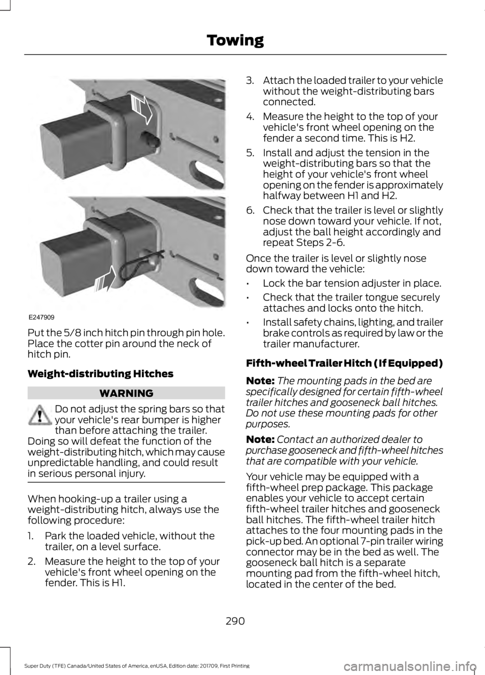
Put the 5/8 inch hitch pin through pin hole.
Place the cotter pin around the neck of
hitch pin.
Weight-distributing Hitches
WARNING
Do not adjust the spring bars so that
your vehicle's rear bumper is higher
than before attaching the trailer.
Doing so will defeat the function of the
weight-distributing hitch, which may cause
unpredictable handling, and could result
in serious personal injury. When hooking-up a trailer using a
weight-distributing hitch, always use the
following procedure:
1. Park the loaded vehicle, without the
trailer, on a level surface.
2. Measure the height to the top of your vehicle's front wheel opening on the
fender. This is H1. 3.
Attach the loaded trailer to your vehicle
without the weight-distributing bars
connected.
4. Measure the height to the top of your vehicle's front wheel opening on the
fender a second time. This is H2.
5. Install and adjust the tension in the weight-distributing bars so that the
height of your vehicle's front wheel
opening on the fender is approximately
halfway between H1 and H2.
6. Check that the trailer is level or slightly
nose down toward your vehicle. If not,
adjust the ball height accordingly and
repeat Steps 2-6.
Once the trailer is level or slightly nose
down toward the vehicle:
• Lock the bar tension adjuster in place.
• Check that the trailer tongue securely
attaches and locks onto the hitch.
• Install safety chains, lighting, and trailer
brake controls as required by law or the
trailer manufacturer.
Fifth-wheel Trailer Hitch (If Equipped)
Note: The mounting pads in the bed are
specifically designed for certain fifth-wheel
trailer hitches and gooseneck ball hitches.
Do not use these mounting pads for other
purposes.
Note: Contact an authorized dealer to
purchase gooseneck and fifth-wheel hitches
that are compatible with your vehicle.
Your vehicle may be equipped with a
fifth-wheel prep package. This package
enables your vehicle to accept certain
fifth-wheel trailer hitches and gooseneck
ball hitches. The fifth-wheel trailer hitch
attaches to the four mounting pads in the
pick-up bed. An optional 7-pin trailer wiring
connector may be in the bed as well. The
gooseneck ball hitch is a separate
mounting pad from the fifth-wheel hitch,
located in the center of the bed.
290
Super Duty (TFE) Canada/United States of America, enUSA, Edition date: 201709, First Printing TowingE247909
Page 360 of 656

Headlamp Aiming Target
8 feet (2.4 meters)
A
Center height of lamp to ground
B
25 feet (7.6 meters)
C
Horizontal reference line
D
Vertical Aim Adjustment Procedure
1. Park the vehicle directly in front of a wall or screen on a level surface,
approximately 25 feet (7.6 meters)
away.
2. Measure the height of the headlamp bulb center from the ground and mark
an 8 foot (2.4 meter) horizontal
reference line on the vertical wall or
screen at this height.
Note: To see a clearer light pattern for
adjusting, you may want to block the light
from one headlamp while adjusting the
other.
3. Turn on the low beam headlamps to illuminate the wall or screen and open
the hood. 4. On the wall or screen you will observe
a flat zone of high intensity light
located at the top of the right hand
portion of the beam pattern. If the top
edge of the high intensity light zone is
not at the horizontal reference line, the
headlamp will need to be adjusted. 5. Locate the vertical adjuster on each
headlamp. Using a Phillips #2
screwdriver, turn the adjuster either
clockwise or counterclockwise in order
to adjust the vertical aim of the
headlamp.
Note: A. LED headlamp.
B. Halogen headlamp.
357
Super Duty (TFE) Canada/United States of America, enUSA, Edition date: 201709, First Printing MaintenanceE142592 E142465 A
B
E223774
Page 389 of 656
B.
215: Indicates the nominal
width of the tire in millimeters
from sidewall edge to sidewall
edge. In general, the larger the
number, the wider the tire.
C. 65:
Indicates the aspect ratio
which gives the tire's ratio of
height to width.
D. R:
Indicates a radial type tire.
E. 15:
Indicates the wheel or rim
diameter in inches. If you change
your wheel size, you will have to
purchase new tires to match the
new wheel diameter.
F. 95:
Indicates the tire's load
index. It is an index that relates to
how much weight a tire can carry.
You may find this information in
your owner ’s manual. If not,
contact a local tire dealer.
Note: You may not find this
information on all tires because it
is not required by federal law.
G. H:
Indicates the tire's speed
rating. The speed rating denotes
the speed at which a tire is
designed to be driven for extended
periods of time under a standard
condition of load and inflation
pressure. The tires on your vehicle
may operate at different
conditions for load and inflation
pressure. These speed ratings may
need to be adjusted for the
difference in conditions. The
ratings range from 81 mph (130
km/h) to 186 mph (299 km/h).
These ratings are listed in the
following chart. Note:
You may not find this
information on all tires because it
is not required by federal law. mph ( km/h)
Letter
rating
81 (130)
M
87 (140)
N
99 (159)
Q
106 (171)
R
112 (180)
S
118 (190)
T
124 (200)
U
130 (210)
H
149 (240)
V
168 (270)
W
186 (299)
Y
Note: For tires with a maximum
speed capability over 149 mph
(240 km/h), tire manufacturers
sometimes use the letters ZR. For
those with a maximum speed
capability over 186 mph (299
km/h), tire manufacturers always
use the letters ZR.
H. U.S. DOT Tire Identification
Number:
This begins with the
letters DOT and indicates that the
tire meets all federal standards.
The next two numbers or letters
are the plant code designating
where it was manufactured, the
next two are the tire size code and
386
Super Duty (TFE) Canada/United States of America, enUSA, Edition date: 201709, First Printing Wheels and Tires
Page 392 of 656
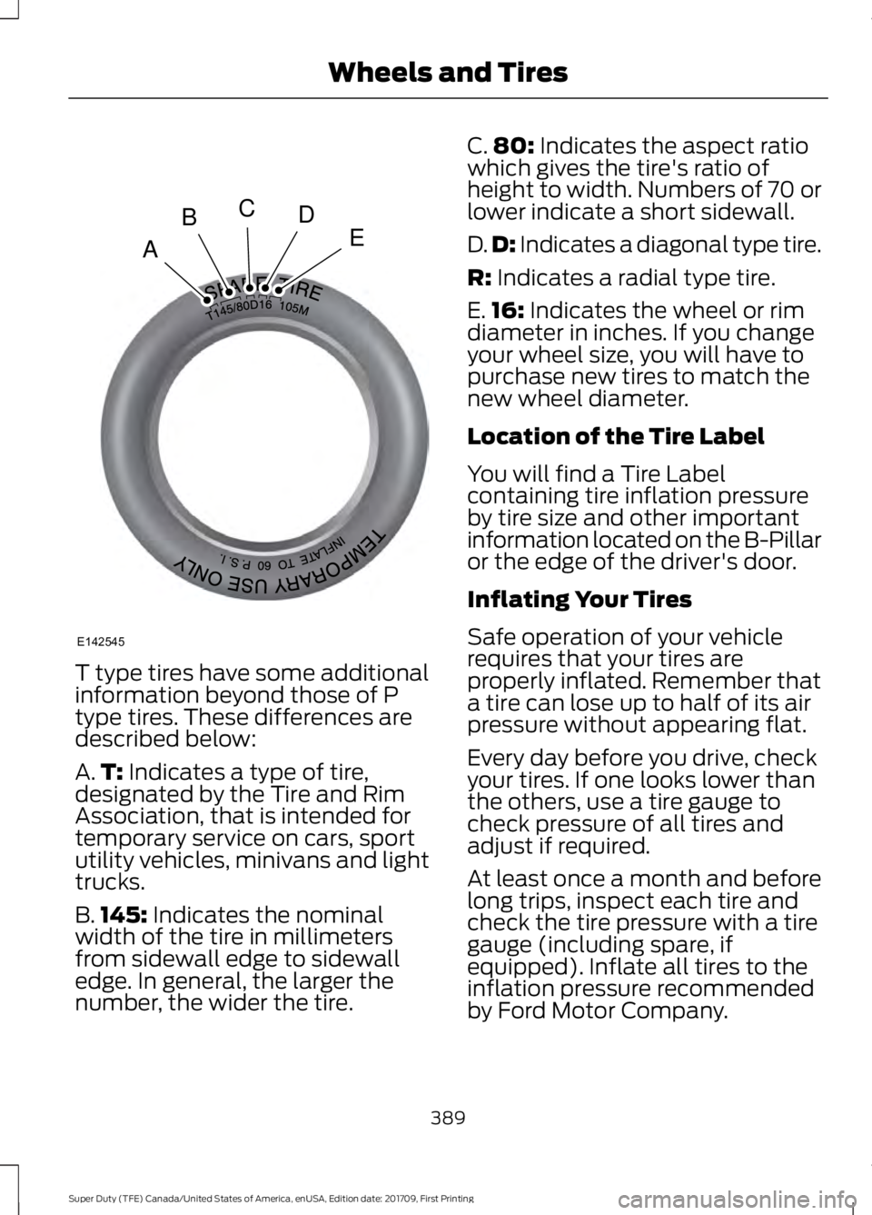
T type tires have some additional
information beyond those of P
type tires. These differences are
described below:
A.
T: Indicates a type of tire,
designated by the Tire and Rim
Association, that is intended for
temporary service on cars, sport
utility vehicles, minivans and light
trucks.
B. 145:
Indicates the nominal
width of the tire in millimeters
from sidewall edge to sidewall
edge. In general, the larger the
number, the wider the tire. C.
80:
Indicates the aspect ratio
which gives the tire's ratio of
height to width. Numbers of 70 or
lower indicate a short sidewall.
D. D:
Indicates a diagonal type tire.
R:
Indicates a radial type tire.
E. 16:
Indicates the wheel or rim
diameter in inches. If you change
your wheel size, you will have to
purchase new tires to match the
new wheel diameter.
Location of the Tire Label
You will find a Tire Label
containing tire inflation pressure
by tire size and other important
information located on the B-Pillar
or the edge of the driver's door.
Inflating Your Tires
Safe operation of your vehicle
requires that your tires are
properly inflated. Remember that
a tire can lose up to half of its air
pressure without appearing flat.
Every day before you drive, check
your tires. If one looks lower than
the others, use a tire gauge to
check pressure of all tires and
adjust if required.
At least once a month and before
long trips, inspect each tire and
check the tire pressure with a tire
gauge (including spare, if
equipped). Inflate all tires to the
inflation pressure recommended
by Ford Motor Company.
389
Super Duty (TFE) Canada/United States of America, enUSA, Edition date: 201709, First Printing Wheels and TiresA
BCDE
E142545
Page 397 of 656
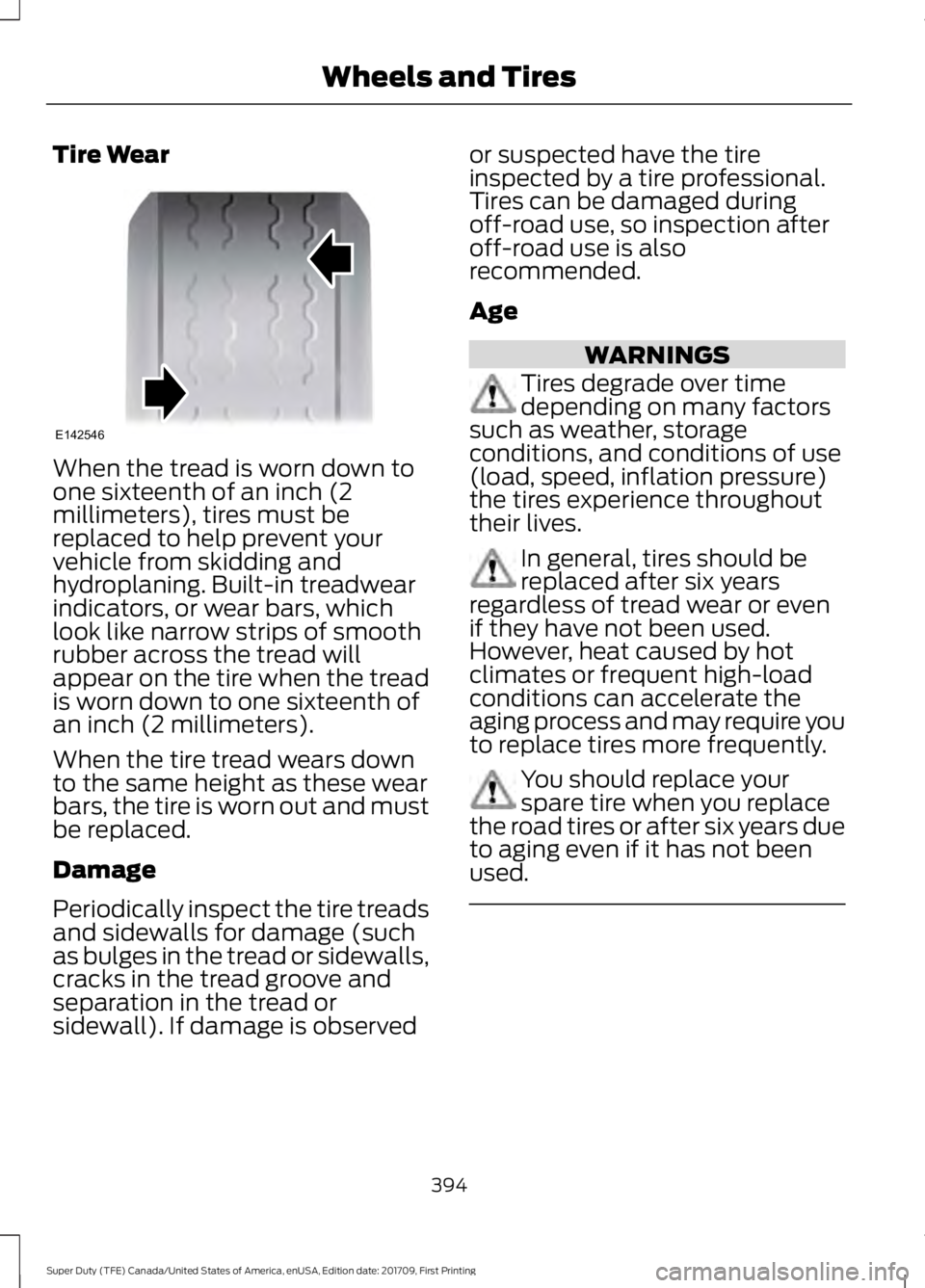
Tire Wear
When the tread is worn down to
one sixteenth of an inch (2
millimeters), tires must be
replaced to help prevent your
vehicle from skidding and
hydroplaning. Built-in treadwear
indicators, or wear bars, which
look like narrow strips of smooth
rubber across the tread will
appear on the tire when the tread
is worn down to one sixteenth of
an inch (2 millimeters).
When the tire tread wears down
to the same height as these wear
bars, the tire is worn out and must
be replaced.
Damage
Periodically inspect the tire treads
and sidewalls for damage (such
as bulges in the tread or sidewalls,
cracks in the tread groove and
separation in the tread or
sidewall). If damage is observed or suspected have the tire
inspected by a tire professional.
Tires can be damaged during
off-road use, so inspection after
off-road use is also
recommended.
Age WARNINGS
Tires degrade over time
depending on many factors
such as weather, storage
conditions, and conditions of use
(load, speed, inflation pressure)
the tires experience throughout
their lives. In general, tires should be
replaced after six years
regardless of tread wear or even
if they have not been used.
However, heat caused by hot
climates or frequent high-load
conditions can accelerate the
aging process and may require you
to replace tires more frequently. You should replace your
spare tire when you replace
the road tires or after six years due
to aging even if it has not been
used. 394
Super Duty (TFE) Canada/United States of America, enUSA, Edition date: 201709, First Printing Wheels and TiresE142546