2018 FORD F450 SUPER DUTY display
[x] Cancel search: displayPage 300 of 656

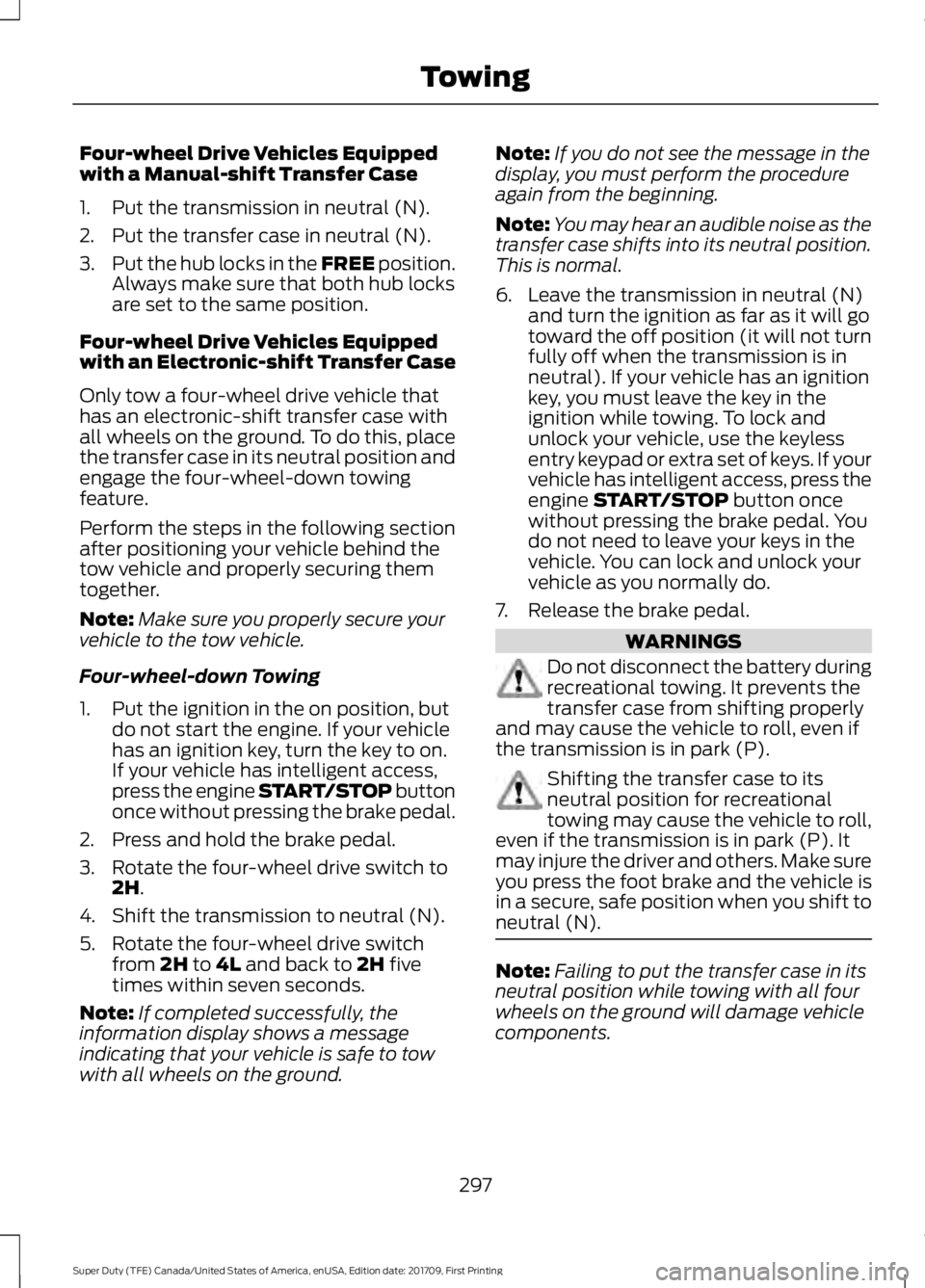
Four-wheel Drive Vehicles Equipped
with a Manual-shift Transfer Case
1. Put the transmission in neutral (N).
2. Put the transfer case in neutral (N).
3.
Put the hub locks in the FREE position.
Always make sure that both hub locks
are set to the same position.
Four-wheel Drive Vehicles Equipped
with an Electronic-shift Transfer Case
Only tow a four-wheel drive vehicle that
has an electronic-shift transfer case with
all wheels on the ground. To do this, place
the transfer case in its neutral position and
engage the four-wheel-down towing
feature.
Perform the steps in the following section
after positioning your vehicle behind the
tow vehicle and properly securing them
together.
Note: Make sure you properly secure your
vehicle to the tow vehicle.
Four-wheel-down Towing
1. Put the ignition in the on position, but do not start the engine. If your vehicle
has an ignition key, turn the key to on.
If your vehicle has intelligent access,
press the engine START/STOP button
once without pressing the brake pedal.
2. Press and hold the brake pedal.
3. Rotate the four-wheel drive switch to 2H.
4. Shift the transmission to neutral (N).
5. Rotate the four-wheel drive switch from
2H to 4L and back to 2H five
times within seven seconds.
Note: If completed successfully, the
information display shows a message
indicating that your vehicle is safe to tow
with all wheels on the ground. Note:
If you do not see the message in the
display, you must perform the procedure
again from the beginning.
Note: You may hear an audible noise as the
transfer case shifts into its neutral position.
This is normal.
6. Leave the transmission in neutral (N) and turn the ignition as far as it will go
toward the off position (it will not turn
fully off when the transmission is in
neutral). If your vehicle has an ignition
key, you must leave the key in the
ignition while towing. To lock and
unlock your vehicle, use the keyless
entry keypad or extra set of keys. If your
vehicle has intelligent access, press the
engine
START/STOP button once
without pressing the brake pedal. You
do not need to leave your keys in the
vehicle. You can lock and unlock your
vehicle as you normally do.
7. Release the brake pedal. WARNINGS
Do not disconnect the battery during
recreational towing. It prevents the
transfer case from shifting properly
and may cause the vehicle to roll, even if
the transmission is in park (P). Shifting the transfer case to its
neutral position for recreational
towing may cause the vehicle to roll,
even if the transmission is in park (P). It
may injure the driver and others. Make sure
you press the foot brake and the vehicle is
in a secure, safe position when you shift to
neutral (N). Note:
Failing to put the transfer case in its
neutral position while towing with all four
wheels on the ground will damage vehicle
components.
297
Super Duty (TFE) Canada/United States of America, enUSA, Edition date: 201709, First Printing Towing
Page 301 of 656

Note:
You can check four-wheel-down
towing status at any time by opening the
driver's door or turning the ignition to the
accessory or on position and verifying a
message displays in the cluster.
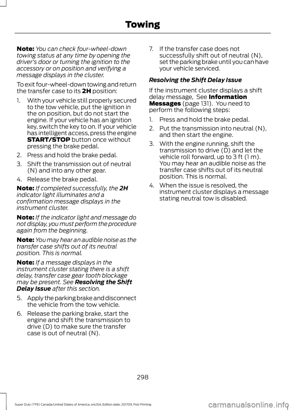
To exit four-wheel-down towing and return
the transfer case to its 2H position:
1. With your vehicle still properly secured
to the tow vehicle, put the ignition in
the on position, but do not start the
engine. If your vehicle has an ignition
key, switch the key to on. If your vehicle
has intelligent access, press the engine
START/STOP
button once without
pressing the brake pedal.
2. Press and hold the brake pedal.
3. Shift the transmission out of neutral (N) and into any other gear.
4. Release the brake pedal.
Note: If completed successfully, the
2H
indicator light illuminates and a
confirmation message displays in the
instrument cluster.
Note: If the indicator light and message do
not display, you must perform the procedure
again from the beginning.
Note: You may hear an audible noise as the
transfer case shifts out of its neutral
position. This is normal.
Note: If a message displays in the
instrument cluster stating there is a shift
delay, transfer case gear tooth blockage
may be present. See
Resolving the Shift
Delay Issue after this section.
5. Apply the parking brake and disconnect
the vehicle from the tow vehicle.
6. Release the parking brake, start the engine and shift the transmission to
drive (D) to make sure the transfer
case is out of neutral (N). 7. If the transfer case does not
successfully shift out of neutral (N),
set the parking brake until you can have
your vehicle serviced.
Resolving the Shift Delay Issue
If the instrument cluster displays a shift
delay message, See
Information
Messages (page 131). You need to
perform the following steps:
1. Press and hold the brake pedal.
2. Put the transmission into neutral (N), and then start the engine.
3. With the engine running, shift the transmission to drive (D) and let the
vehicle roll forward, up to
3 ft (1 m).
You may hear an audible noise as the
transfer case shifts out of its neutral
position. This is normal.
4. When the issue is resolved, the instrument cluster displays a message
stating neutral tow is disabled.
298
Super Duty (TFE) Canada/United States of America, enUSA, Edition date: 201709, First Printing Towing
Page 328 of 656

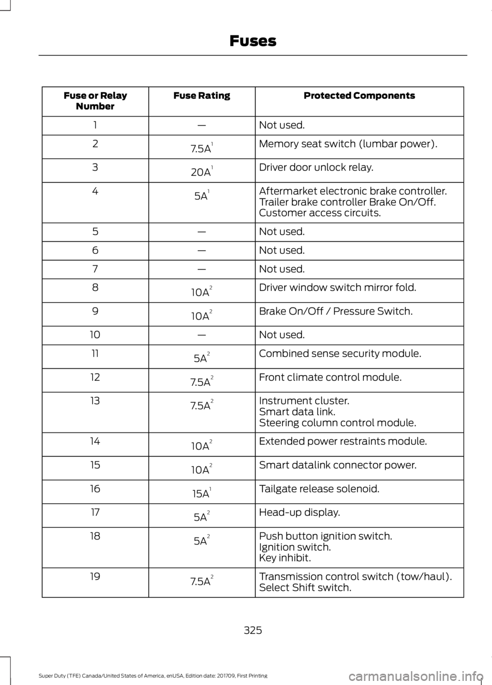
Protected Components
Fuse Rating
Fuse or Relay
Number
Not used.
—
1
Memory seat switch (lumbar power).
7.5A 1
2
Driver door unlock relay.
20A 1
3
Aftermarket electronic brake controller.
5A 1
4
Trailer brake controller Brake On/Off.
Customer access circuits.
Not used.
—
5
Not used.
—
6
Not used.
—
7
Driver window switch mirror fold.
10A 2
8
Brake On/Off / Pressure Switch.
10A 2
9
Not used.
—
10
Combined sense security module.
5A 2
11
Front climate control module.
7.5A 2
12
Instrument cluster.
7.5A 2
13
Smart data link.
Steering column control module.
Extended power restraints module.
10A 2
14
Smart datalink connector power.
10A 2
15
Tailgate release solenoid.
15A 1
16
Head-up display.
5A 2
17
Push button ignition switch.
5A 2
18
Ignition switch.
Key inhibit.
Transmission control switch (tow/haul).
7.5A 2
19
Select Shift switch.
325
Super Duty (TFE) Canada/United States of America, enUSA, Edition date: 201709, First Printing Fuses
Page 329 of 656

Protected Components
Fuse Rating
Fuse or Relay
Number
Active front steering module.
7.5A 2
20
Head-up display.
5A 2
21
Humidity sensor.
Upfitter switch.
5A 2
22
Run/Start.
PTO relays.
Accessory delay.
10A 1
23
Power windows.
Moonroof.
Power folding mirrors relay.
Inverter.
Window/moonroof switch illumination.
Central locking system relay.
20A 1
24
Left-hand front smart window motor.
30A 1
25
Door zone module.
Right-hand front smart window motor.
30A 1
26
Door zone module.
Moonroof.
30A 1
27
Sony amplifier - 10 channel.
20A 1
28
Not used.
—
29
Not used.
—
30
Adjustable pedals switch.
15A 1
31
SYNC.
10A 1
32
GPS module.
Display.
Radio frequency receiver.
Radio.
20A 1
33
Run-start relay.
30A 1
34
Extended power restraints module.
5A 1
35
326
Super Duty (TFE) Canada/United States of America, enUSA, Edition date: 201709, First Printing Fuses
Page 339 of 656

Note:
If the oil level is between the
maximum and minimum marks, the oil level
is acceptable. Do not add oil.
Note: The oil consumption of new engines
reaches its normal level after approximately
3,000 mi (5,000 km).
Adding Engine Oil WARNING
Do not remove the filler cap when
the engine is running.
Do not use supplemental engine oil
additives because they are unnecessary
and could lead to engine damage that may
not be covered by the vehicle Warranty.
To top up the engine oil level do the
following:
1. Clean the area surrounding the engine
oil filler cap before you remove it.
2. Remove the engine oil filler cap. See Under Hood Overview
(page 331).
Turn it counterclockwise and remove
it.
3. Add engine oil of the proper viscosity and grade that meets Ford
specifications. See
Capacities and
Specifications (page 433). You may
have to use a funnel to pour the engine
oil into the opening.
4. Recheck the oil level.
5. If the oil level is correct, replace the dipstick and make sure it is fully seated.
6. Replace the engine oil filler cap. Turn it clockwise until you feel a strong
resistance.
Note: Do not add oil further than the
maximum mark. Oil levels above the
maximum mark may cause engine damage.
Note: Make sure you install the oil filler cap
correctly. Note:
Soak up any spillage with an
absorbent cloth immediately.
Engine lubrication for severe
service operation
The following conditions define severe
operation for which engine operation with
SAE 5W-40 oil which meets Ford
specification, WSS-M2C171-F1, is
recommended. Oil and oil filter change
intervals will be determined by the
Intelligent Oil Life Monitor™ as noted
previously.
CHANGING THE ENGINE OIL
AND OIL FILTER WARNINGS
Do not handle a hot oil filter with
bare hands.
Continuous contact with used motor
oil has caused cancer in laboratory
mice. Protect your skin by washing
with soap and water. If your vehicle is equipped with a diesel
engine, an Intelligent Oil Life Monitor™
calculates the proper oil change service
interval. When the information display
indicates: OIL CHANGE REQUIRED, change
the engine oil and oil filter. See
Information Displays
(page 114).
The engine oil filter protects your engine
by filtering harmful, abrasive or sludge
particles and particles significantly smaller
than most available will-fit filters. See
Motorcraft Parts
(page 423).
1. Unscrew the oil filter and oil pan drain plug and wait for the oil to drain.
2. Replace the filter.
3. Reinstall the oil pan drain plug.
336
Super Duty (TFE) Canada/United States of America, enUSA, Edition date: 201709, First Printing Maintenance
Page 340 of 656

4. Refill the engine with new oil. See
Capacities and Specifications (page
433).
5. For diesel engines, you need to reset the Intelligent Oil Life Monitor™. See
Information Displays
(page 114).
Engine lubrication for severe
service operation
The following conditions define severe
operation for which engine operation with
SAE 5W-40 API CJ-4 is recommended. Oil
and oil filter change intervals will be
determined by the Intelligent Oil Life
Monitor™ as noted previously.
• Frequent or extended idling (over 10
minutes per hour of normal driving).
• Low-speed operation/stationary use.
• If vehicle is operated in sustained
ambient temperatures below
-9°F
(-23°C) or above 100°F (38°C).
• Frequent low-speed operation,
consistent heavy traffic less than
25 mph (40 km/h)
.
• Operating in severe dust conditions.
• Operating the vehicle off road.
• Towing a trailer over
1,000 mi
(1,600 km).
• Sustained, high-speed driving at Gross
Vehicle Weight Rating (maximum
loaded weight for vehicle operation).
• Use of fuels with sulfur content other
than ultra-low sulfur diesel (ULSD).
• Use of high-sulfur diesel fuel. CHANGING THE CRANKCASE
VENT FILTER ELEMENT
(If
Equipped) WARNING
Do not dispose of engine oil or oil
filters in the household refuse or the
public sewage system. Use an
authorized waste disposal facility. Do not clean or recondition the filter
element.
We recommend that you demand the use
of genuine Ford and Motorcraft® parts
whenever your vehicle requires scheduled
maintenance or repair. Use the correct
specification filter element. See
Capacities and Specifications
(page
433).
Note: Operating your vehicle without a filter
element or with an unapproved filter
element may result in damage to the turbo
charger or exchanger and could lead to
engine damage that may not be covered by
the vehicle Warranty.
337
Super Duty (TFE) Canada/United States of America, enUSA, Edition date: 201709, First Printing Maintenance
Page 341 of 656

Filter cover.
A
Filter element.
B
Filter housing.
C
1. Clean the filter cover and remove the bolts.
2. Carefully remove the filter cover.
3. Remove used filter element from the filter housing and carefully dispose of
it.
4. Make sure that the sealing surfaces on
the filter housing and cover are clean
and free of debris.
5. Install the new filter element.
6. Install the filter cover.
7. Install the bolts finger-tight. 8.
Fully tighten all of the bolts to between
3–4 lb.ft (4.5–6 Nm) in the sequence
shown.
9. Record the engine mileage and update
the service log accordingly.
OIL CHANGE INDICATOR
RESET
Use the information display controls on
the steering wheel to reset the oil change
indicator.
From the main menu scroll to: Action and description
Message
Press the right arrow button,
then from this menu scroll
to the following message.
Settings
Press the right arrow button,
then from this menu scroll
to the following message.
Conveni-
ence
Press the right arrow button,
then from this menu scroll
to the following message.
Oil Life
Reset
338
Super Duty (TFE) Canada/United States of America, enUSA, Edition date: 201709, First Printing MaintenanceE211403
A
B
C E211404
165
4
32
7
Page 342 of 656

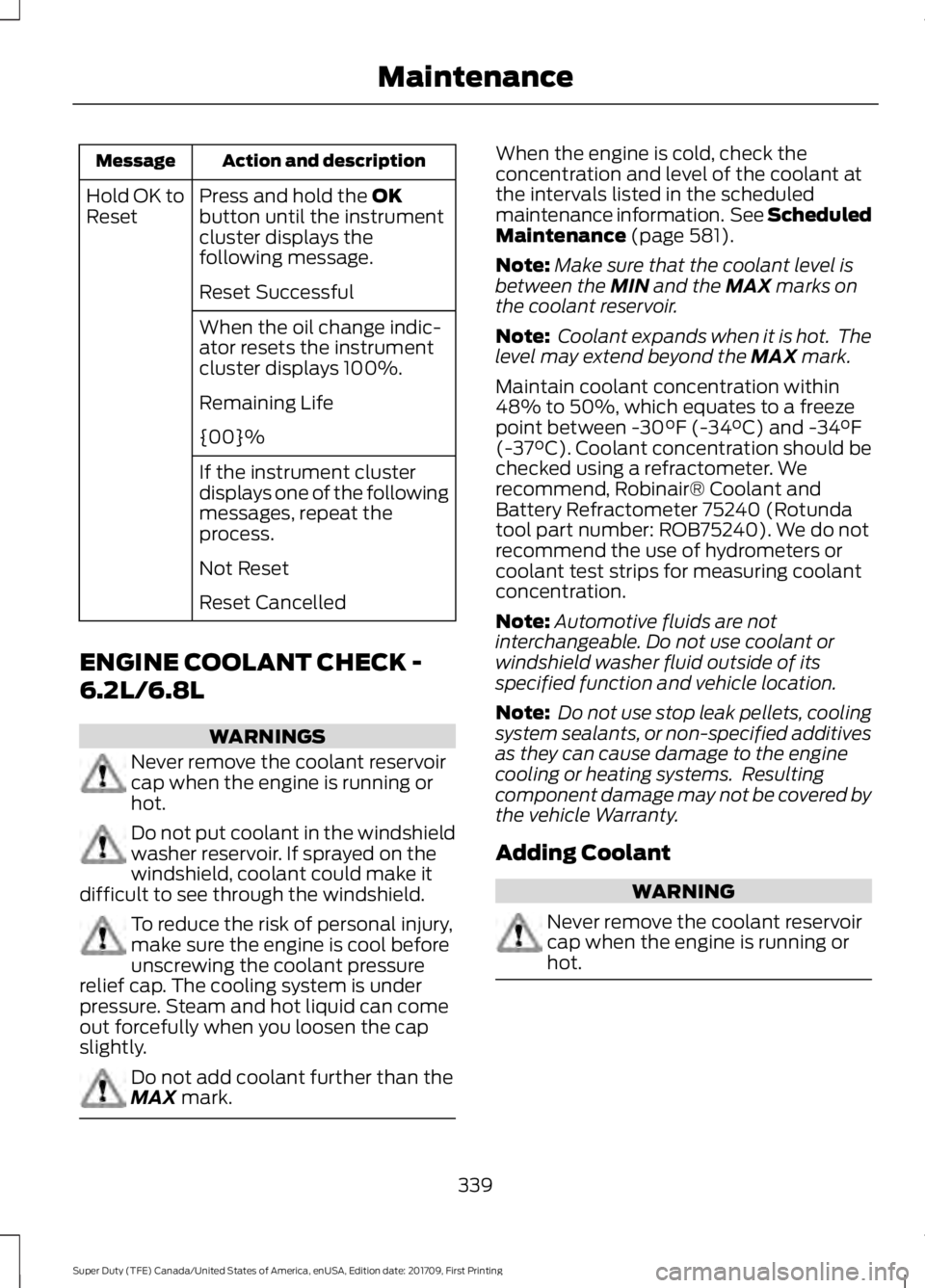
Action and description
Message
Press and hold the OK
button until the instrument
cluster displays the
following message.
Hold OK to
Reset
Reset Successful
When the oil change indic-
ator resets the instrument
cluster displays 100%.
Remaining Life
{00}%
If the instrument cluster
displays one of the following
messages, repeat the
process.
Not Reset
Reset Cancelled
ENGINE COOLANT CHECK -
6.2L/6.8L WARNINGS
Never remove the coolant reservoir
cap when the engine is running or
hot.
Do not put coolant in the windshield
washer reservoir. If sprayed on the
windshield, coolant could make it
difficult to see through the windshield. To reduce the risk of personal injury,
make sure the engine is cool before
unscrewing the coolant pressure
relief cap. The cooling system is under
pressure. Steam and hot liquid can come
out forcefully when you loosen the cap
slightly. Do not add coolant further than the
MAX
mark. When the engine is cold, check the
concentration and level of the coolant at
the intervals listed in the scheduled
maintenance information. See Scheduled
Maintenance
(page 581).
Note: Make sure that the coolant level is
between the
MIN and the MAX marks on
the coolant reservoir.
Note: Coolant expands when it is hot. The
level may extend beyond the
MAX mark.
Maintain coolant concentration within
48% to 50%, which equates to a freeze
point between -30°F (-34°C) and -34°F
(-37°C). Coolant concentration should be
checked using a refractometer. We
recommend, Robinair® Coolant and
Battery Refractometer 75240 (Rotunda
tool part number: ROB75240). We do not
recommend the use of hydrometers or
coolant test strips for measuring coolant
concentration.
Note: Automotive fluids are not
interchangeable. Do not use coolant or
windshield washer fluid outside of its
specified function and vehicle location.
Note: Do not use stop leak pellets, cooling
system sealants, or non-specified additives
as they can cause damage to the engine
cooling or heating systems. Resulting
component damage may not be covered by
the vehicle Warranty.
Adding Coolant WARNING
Never remove the coolant reservoir
cap when the engine is running or
hot.
339
Super Duty (TFE) Canada/United States of America, enUSA, Edition date: 201709, First Printing Maintenance