2018 FORD F-550 display
[x] Cancel search: displayPage 280 of 660
Step 5: Enter Measurements Using the
Information Display
Using the measurements you recorded,
enter the required data into the system.
Follow the on screen prompts to enter
each of the measurements taken in step
4. Use the up and down arrows to increase
or decrease the numbers as necessary.
Press OK to confirm each measurement.
Once you add the last measurement, the
information display shows all of the
entered measurements. You can choose
to confirm or change the measurements.
Step 6: Confirming the Sticker Location
Check the rear view camera display to see
if the system identifies the sticker. The
system marks the sticker with a red circle.
Confirm that the red circle shows over the
sticker image in the rear view camera
display.
Note:
If the system cannot locate the
sticker, try cleaning the camera lens. Make
sure the sticker is within the zone as
indicated in step 3.
The information display shows a
confirmation message when you
successfully confirm the target.
Calibrating the System
To complete setup, drive your vehicle
straight forward between 4– 24 mph
(6– 39 km/h), as directed by the
information display.
Note: Keep the steering wheel straight
during the calibration process. If the steering
wheel is in a turned position, the calibration
pauses. The information display prompts
you to drive straight forward to complete
the calibration.
The information display shows a message
during calibration and after calibration is
complete Note:
For best results, do not calibrate the
system at night.
Using Trailer Reverse Guidance
1. Shift into reverse (R). Press the rear camera button to expand the menu.
2. Press the trailer icon.
3. Select the applicable trailer in the information display.
4. When in trailer reverse guidance mode,
you can see the camera view on the
side your trailer is moving, or both sides
when the trailer is straight behind you.
When the views change with the trailer
direction, it is called auto mode. For
example, if you turn the trailer to the
right, you see the right side of your
vehicle and trailer. You can switch this
view manually at any time by using the
arrow keys. To return to auto mode,
press the auto button.
Note: Auto mode is the default setting.
Use the view that helps you the most when
reversing your vehicle and trailer. Normal rear view camera view.
Use this feature when you want
to see your trailer hitch or what
is directly behind your vehicle. Straight back-up mode. Use this
feature when you want to keep
your trailer completely in line
with your truck. In this mode, a steering
wheel graphic shows you which way to turn
your steering wheel to keep your trailer
straight.
Note: It may be helpful to shift your vehicle
into drive (D), pull forward and straighten
out the vehicle and trailer before engaging
straight back-up mode.
Left and right arrows let you see other
views regardless of your trailer angle. Use
them to switch views manually.
277
Super Duty (TFE) Canada/United States of America, enUSA, Edition date: 201709, Second Printing TowingE263194 E224484
Page 281 of 660
Note:
If you're using a fifth wheel or goose
neck trailer, or if you have not set up the
trailer reverse guidance system, auto view
is not available.
To change your view, use the arrows. You
can see the following views:
• Full driver.
• Partial driver.
• 50/50.
• Partial passenger.
• Full passenger. Zoom. Use this feature to zoom
in the camera view.
Return. Ths feature takes you
back to the 360-degree camera
system and out of the trailer
reverse guidance feature. Auto. Ths feature returns you to
auto view.
In addition to multiple view options, your
touchscreen adds some features to give
you more information. For example, after
setting up a conventional trailer, the
display shows a small top-view
representation of your truck and trailer.
This representation shows two,
different-colored lines: A black line shows
you where your trailer is in relation to your
vehicle. A white line gives you a projection
of where your trailer may go based on your
current steering wheel position
Note: When you move the steering wheel,
the white line indicates where the trailer
may go based on your steering wheel input.
When you turn your steering wheel to the
left, the trailer moves to the right. When you
turn your steering wheel to the right, the
trailer moves to the left. When you turn the steering wheel, a small
representation shows you two zones to
warn you of a possible jackknife condition.
The view shows your truck and trailer
position and provides visual feedback to
help avoid a jackknife condition entirely.
The yellow zone warns you of a potential
jackknife position. When you enter into this
zone, it is recommended to put your vehicle
back into drive (D) and pull forward.
Moving forward helps put the truck and
trailer back into an in-line position.
The red zone indicates that you need to
put the truck into drive (D) and pull
forward immediately.
Troubleshooting
Note:
The system requires a clear view of
the sticker placed on the trailer. You must
keep the camera lens and sticker clean for
the system to operate correctly.
Setup
The system is designed to be used with a
wide variety of trailers. However, there are
some trailers that do not have a proper
surface and location to mount the sticker.
These trailers are not supported. Attempts
to place the sticker on a surface that does
not meet the sticker placement
requirement listed in Step 3 of the setup
instruction, or entering inaccurate
measurements to proceed through setup
can result in improper system function.
Accurate measurements are critical to
correct system function. If you need to
check measurements or change them, you
can access them through the trailer menus
in the information display. Choose the
option to change the sticker from the
change trailer settings menu. It is not
necessary to remove the sticker if you are
just reviewing or changing measurements.
278
Super Duty (TFE) Canada/United States of America, enUSA, Edition date: 201709, Second Printing TowingE224485 E224486 E224487
Page 282 of 660
The following menu warnings or difficulties
may occur during setup. Tips to resolve
them are listed below.
Measurement A has reached maximum or
minimum value:
•
The system is designed to work with
drawbars that have a license plate to
hitch ball center measurement of
9–16 in (229–406 mm) when installed.
Do not attempt to use drawbars that
have a length outside this range as
system performance degrades and
could cause improper system function.
• Make sure that the measurement being
made is the horizontal distance only
from license plate and the hitch ball
center. A straight line distance that
includes any vertical rise or drop
increases the measurement and makes
it inaccurate. Inaccurate
measurements degrade system
performance and could cause improper
system function. See step 4 of the
setup instruction to review the
measurement instructions.
Measurement B has reached maximum or
minimum value:
• Make sure you follow the sticker
placement instruction in step 3 of the
setup. Stickers placed outside the
allowed zone adversely affect the
system performance and could cause
improper feature function.
• Make sure that the measurement being
made is the horizontal distance only
from center of sticker to the hitch ball
center. A straight line distance that
includes any vertical rise or drop
increases the measurement and
causes an inaccurate value to be
entered into the system. See step 4 of
the setup for additional measurement
instructions. Measurement C has reached maximum or
minimum value:
•
Make sure you follow the sticker
placement instructions in step 3 of the
setup. Stickers placed outside the
allowed zone adversely affect the
system performance and could cause
improper feature function. If you have
met all the criteria for sticker
placement and you see this message,
the sticker is either too far below or too
close to the camera to properly
recognize the sticker. In order for the
system to correctly operate, the sticker
height must be lowered if you receive
the minimum warning or the sticker
height must be raised if you receive the
maximum warning.
•Only one sticker can be placed on
the trailer for correct system
function. The previous sticker must
be removed or covered so only one
sticker is visible to the camera.
• Measurement B and C must be
measured again if a new sticker is
placed on the trailer.
Measurement D has reached maximum or
minimum value:
• Make sure that the measurement being
made is the horizontal distance only
from tailgate to the center of the single
axle or the center of all the axles on the
trailer. See step 4 of the setup for
additional measurement instructions.
The system does not support trailer
lengths outside the range allowed by
the information display.
279
Super Duty (TFE) Canada/United States of America, enUSA, Edition date: 201709, Second Printing Towing
Page 283 of 660
System is circling something beside the
sticker or system cannot find the sticker:
•
Make sure the rear camera is clean and
the sticker is clearly visible in the
camera image. Clean the camera and
sticker if necessary.
• The camera system uses the entered
measurements to help locate the
sticker. Inaccurate sticker
measurements degrade the system's
ability to locate the sticker. Verify the
measurements entered into the system
are accurate.
• Remove the incorrectly circled label or
decal if possible.
• If you cannot resolve the issue, a new
sticker location should be tried. The
new sticker location must meet the
requirements noted in step 3 of the
setup instructions. Only one sticker can
be placed on the trailer for correct
system function. The previous sticker
must be removed or covered so only
one sticker is visible to the camera.
Calibration
The system monitors various vehicle
parameters to ensure your vehicle is being
driven straight and the trailer straight
behind your vehicle. Any steering input or
trailer movement pauses the calibration.
For best results:
• Use a long, straight and smooth road
when attempting to calibrate.
• Drive straight forward.
• Drive between 4–24 mph
(6– 39 km/h).
System Operation
The following warnings or difficulties may
occur during feature operation. Tips to
resolve them are listed below. The system is not available:
•
The system relies on many
sub-systems in your vehicle to correctly
operate. If those sub-systems are not
correctly operating, the system may
not be available.
•Low battery voltage is one
condition which prevents the
system from operating. Please
make sure the battery is correctly
charged if the system is not
available.
• You may need to drive your vehicle
straight forward above
25 mph
(40 km/h) before the system is
available again.
• If the message still displays, take your
vehicle to an authorized dealer for
service.
Sticker lost:
• Check for the following if you receive
the lost sticker message when using
the system.
•Stop your vehicle as soon as the
message displays.
• Make sure the sticker is visible in
the rear view camera image.
• Clean the sticker and camera to
make sure they are unobstructed.
• Remove any items that may be
blocking the view of the sticker.
Depending on your trailer
configuration and any equipment
mounted to your trailer, it is
possible for the sticker to be
blocked from the view of the
camera as it rotates on the hitch
ball, but not be blocked during
setup. Remove the obstruction if
possible. It may be necessary to
280
Super Duty (TFE) Canada/United States of America, enUSA, Edition date: 201709, Second Printing Towing
Page 285 of 660
Note:
In some cases, if vehicle speed is too
high, the system may activate multiple
times, gradually reducing vehicle speed.
This feature applies your vehicle brakes at
individual wheels and, if necessary, reduces
engine power. If the trailer begins to sway,
the stability control light flashes and the
message TRAILER SWAY REDUCE
SPEED appears in the information display.
The first thing to do is slow your vehicle
down, then pull safely to the side of the
road and check for proper tongue load and
trailer load distribution. See
Load
Carrying (page 264).
RECOMMENDED TOWING
WEIGHTS WARNING
You must use the heavy-duty
drawbar pin supplied with
your vehicle when using the
heavy-duty hitch. Failure to follow
this instruction could result in the
loss of control of your vehicle,
personal injury or death. Note:
Vehicles with a heavy-duty
hitch must use the drawbar pin
stamped 21,000 LBS. You can
obtain a replacement drawbar pin
at your authorized dealer. Note:
Make sure to take into
consideration trailer frontal area.
Do not exceed 60 ft 2
(5.6 m 2
) trailer
frontal area for conventional
trailers. Do not exceed 75 ft 2
(6.9
m 2
) trailer frontal area for fifth
wheel and gooseneck trailers.
Note: Exceeding this limitation
may significantly reduce the
performance of your towing
vehicle. Selecting a trailer with a
low aerodynamic drag and rounded
front design helps optimize
performance and fuel economy.
Note: For high altitude operation,
reduce the gross combined weight
by 2% per
1,000 ft (300 m)
starting at the 1,000 ft (300 m)
elevation point.
Note: Certain states require
electric trailer brakes for trailers
over a specified weight. Be sure to
check state regulations for this
specified weight. The maximum
trailer weights listed may be limited
to this specified weight, as your
vehicle's electrical system may not
include the wiring connector
needed to use electric trailer
brakes.
Your vehicle may tow a trailer
provided the maximum trailer
weight is less than or equal to the
maximum trailer weight
calculated using the formula
following the chart.
282
Super Duty (TFE) Canada/United States of America, enUSA, Edition date: 201709, Second Printing Towing
Page 290 of 660
Note:
If your vehicle is equipped with a
factory brake controller, the Battery (+)
Orange wire is powered when you start the
engine and you apply the brakes at least
once when a trailer with brake lamps is
connected. If your vehicle is not equipped
with a factory brake controller, relays control
the system and it becomes active when you
power on your vehicle.
Dynamic Hitching Using the Rear
View Camera System
Note: Active guidelines and fixed guidelines
are only available when the transmission is
in reverse (R).
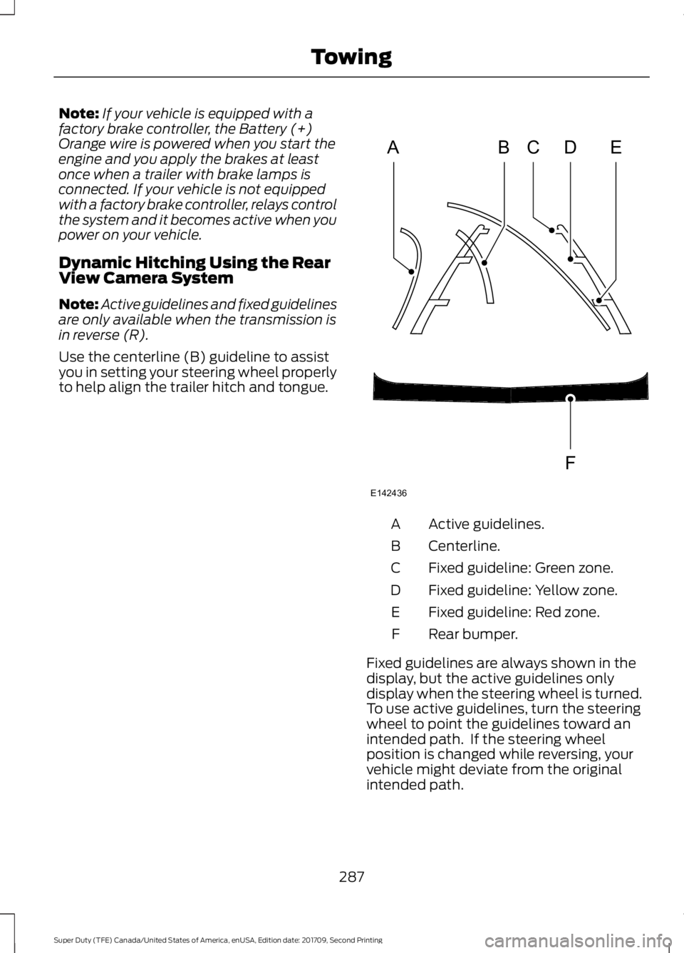
Use the centerline (B) guideline to assist
you in setting your steering wheel properly
to help align the trailer hitch and tongue. Active guidelines.
A
Centerline.
B
Fixed guideline: Green zone.
C
Fixed guideline: Yellow zone.
D
Fixed guideline: Red zone.
E
Rear bumper.
F
Fixed guidelines are always shown in the
display, but the active guidelines only
display when the steering wheel is turned.
To use active guidelines, turn the steering
wheel to point the guidelines toward an
intended path. If the steering wheel
position is changed while reversing, your
vehicle might deviate from the original
intended path.
287
Super Duty (TFE) Canada/United States of America, enUSA, Edition date: 201709, Second Printing TowingABCD
F
E
E142436
Page 294 of 660
Note:
The integrated Ford brake controller
is compatible with trailers equipped with
electric-actuated drum brakes and
electric-over hydraulic brake systems.
Note: The integrated Ford brake controller
does not control hydraulic surge-style
brakes. When used properly, the trailer brake
controller assists in smooth and effective
trailer braking by powering the trailer
’s
electric or electric-over-hydraulic brakes
with a proportional output based on the
towing vehicle ’s brake pressure.
You can adjust the amount of initial trailer
brake output by selecting one of three
settings through the message center.
Ford has tested the trailer brake controller
to be compatible with several major
brands of electric-over-hydraulic trailer
brakes. Contact an authorized dealer for
information on which brands you can use.
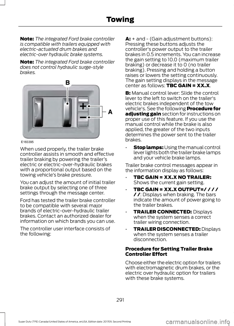
The controller user interface consists of
the following: A: + and - (Gain adjustment buttons):
Pressing these buttons adjusts the
controller's power output to the trailer
brakes in 0.5 increments. You can increase
the gain setting to 10.0 (maximum trailer
braking) or decrease it to 0 (no trailer
braking). Pressing and holding a button
raises or lowers the setting continuously.
The gain setting displays in the message
center as follows:
TBC GAIN = XX.X.
B:
Manual control lever: Slide the control
lever to the left to switch on the trailer's
electric brakes independent of the tow
vehicle's. See the following Procedure for
adjusting gain section for instructions on
proper use of this feature. If you use the
manual control while the brake is also
applied, the greater of the two inputs
determines the power sent to the trailer
brakes.
• Stop lamps: Using the manual control
lever lights both the trailer brake lamps
and your vehicle brake lamps.
Trailer brake control messages appear in
the information display as follows:
• TBC GAIN = XX.X NO TRAILER:
Shows the current gain setting.
• TBC GAIN = XX.X OUTPUT=/ / / /
/ /
: Displays when braking. The bars
indicate the amount of power going to
the trailer brakes.
• TRAILER CONNECTED:
Displays
when the system senses a correct
trailer wiring connection.
• TRAILER DISCONNECTED: Displays
when the system senses a trailer
disconnection.
Procedure for Setting Trailer Brake
Controller Effort
Choose either the electric option for trailers
with electromagnetic drum brakes, or the
electric over hydraulic option for trailers
with these brake systems.
291
Super Duty (TFE) Canada/United States of America, enUSA, Edition date: 201709, Second Printing TowingE183395
Page 295 of 660
Trailer Brake Effort Setting
The trailer brake controller allows the user
to customize how aggressively the trailer
brakes engage. The default value is the low
setting and is the recommended setting
for most trailers. If your trailer's brakes
require more initial voltage, or if you prefer
more aggressive trailer braking, then select
either the medium or the high setting.
Procedure for Setting Trailer Brake
Controller Mode
Choose the low, medium or high setting
for the required initial trailer brake output.
Procedure for Adjusting Gain
Note:
Only perform this procedure in a
traffic-free environment at speeds of
approximately 20– 25 mph (30–40 km/h).
The gain setting adjusts the trailer brake
controller for the specific towing condition.
You should change the setting as towing
conditions change. Changes to towing
conditions include trailer load, vehicle load,
road conditions and weather.
The gain should be set to provide the
maximum trailer braking assistance while
making sure the trailer wheels do not lock
when using the brakes. Locked trailer
wheels may lead to trailer instability.
1. Make sure the trailer brakes are in good
working condition, functioning normally
and properly adjusted. See your trailer
dealer if necessary.
2. Hook up the trailer and make the electrical connections according to the
trailer manufacturer's instructions.
3. When you plug in a trailer with electric or electric-over-hydraulic brakes, a
confirmation message appears in the
information display. 4. Use the gain adjustment (+ and -)
buttons to increase or decrease the
gain setting to the desired starting
point. A gain setting of 6.0 is a good
starting point for heavier loads.
5. In a traffic-free environment, tow the trailer on a dry, level surface at a speed
of
20– 25 mph (30–40 km/h) and
squeeze the manual control lever
completely.
6. If the trailer wheels lock up, indicated by squealing tires, reduce the gain
setting. If the trailer wheels turn freely,
increase the gain setting. Repeat Steps
5 and 6 until the gain setting is at a
point just below trailer wheel lock-up.
If towing a heavier trailer, trailer wheel
lock-up may not be attainable even
with the maximum gain setting of 10.
Information Display Warning Messages
Note: An authorized dealer can diagnose
the trailer brake controller to determine
exactly which trailer fault has occurred.
However, your Ford warranty does not cover
this diagnosis if the fault is with the trailer.
TRAILER BRAKE MODULE FAULT
Displays in response to faults sensed by
the trailer brake controller, accompanied
by a single tone. If this message appears,
contact an authorized dealer as soon as
possible for diagnosis and repair. The
controller may still function, but with
degraded performance.
WIRING FAULT ON TRAILER
Displays when there is a short circuit on
the electric brake output wire.
If this message displays, with no trailer
connected, the problem is with your vehicle
wiring or trailer brake controller. Contact
an authorized dealer.
292
Super Duty (TFE) Canada/United States of America, enUSA, Edition date: 201709, Second Printing Towing