2018 FORD F-550 trailer
[x] Cancel search: trailerPage 327 of 660
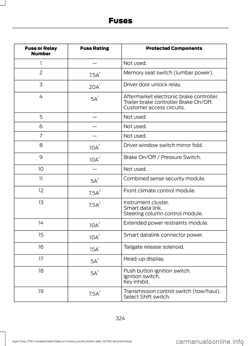
Protected Components
Fuse Rating
Fuse or Relay
Number
Not used.
—
1
Memory seat switch (lumbar power).
7.5A 1
2
Driver door unlock relay.
20A 1
3
Aftermarket electronic brake controller.
5A 1
4
Trailer brake controller Brake On/Off.
Customer access circuits.
Not used.
—
5
Not used.
—
6
Not used.
—
7
Driver window switch mirror fold.
10A 2
8
Brake On/Off / Pressure Switch.
10A 2
9
Not used.
—
10
Combined sense security module.
5A 2
11
Front climate control module.
7.5A 2
12
Instrument cluster.
7.5A 2
13
Smart data link.
Steering column control module.
Extended power restraints module.
10A 2
14
Smart datalink connector power.
10A 2
15
Tailgate release solenoid.
15A 1
16
Head-up display.
5A 2
17
Push button ignition switch.
5A 2
18
Ignition switch.
Key inhibit.
Transmission control switch (tow/haul).
7.5A 2
19
Select Shift switch.
324
Super Duty (TFE) Canada/United States of America, enUSA, Edition date: 201709, Second Printing Fuses
Page 339 of 660
4. Refill the engine with new oil. See
Capacities and Specifications (page
432).
5. For diesel engines, you need to reset the Intelligent Oil Life Monitor™. See
Information Displays
(page 113).
Engine lubrication for severe
service operation
The following conditions define severe
operation for which engine operation with
SAE 5W-40 API CJ-4 is recommended. Oil
and oil filter change intervals will be
determined by the Intelligent Oil Life
Monitor™ as noted previously.
• Frequent or extended idling (over 10
minutes per hour of normal driving).
• Low-speed operation/stationary use.
• If vehicle is operated in sustained
ambient temperatures below
-9°F
(-23°C) or above 100°F (38°C).
• Frequent low-speed operation,
consistent heavy traffic less than
25 mph (40 km/h)
.
• Operating in severe dust conditions.
• Operating the vehicle off road.
• Towing a trailer over
1,000 mi
(1,600 km).
• Sustained, high-speed driving at Gross
Vehicle Weight Rating (maximum
loaded weight for vehicle operation).
• Use of fuels with sulfur content other
than ultra-low sulfur diesel (ULSD).
• Use of high-sulfur diesel fuel. CHANGING THE CRANKCASE
VENT FILTER ELEMENT
(If
Equipped) WARNING
Do not dispose of engine oil or oil
filters in the household refuse or the
public sewage system. Use an
authorized waste disposal facility. Do not clean or recondition the filter
element.
We recommend that you demand the use
of genuine Ford and Motorcraft® parts
whenever your vehicle requires scheduled
maintenance or repair. Use the correct
specification filter element. See
Capacities and Specifications
(page
432).
Note: Operating your vehicle without a filter
element or with an unapproved filter
element may result in damage to the turbo
charger or exchanger and could lead to
engine damage that may not be covered by
the vehicle Warranty.
336
Super Duty (TFE) Canada/United States of America, enUSA, Edition date: 201709, Second Printing Maintenance
Page 344 of 660
Remember that the engine is capable of
automatically shutting down to prevent
engine damage. In this situation:
1. Pull off the road as soon as safely
possible and switch the engine off.
2. If you are a member of a roadside assistance program, we recommend
that you contact your roadside
assistance service provider.
3. If this is not possible, wait a short period for the engine to cool.
4. Check the coolant level. If the coolant level is at or below the minimum mark,
add prediluted coolant immediately.
5. When the engine temperature cools, you can re-start the engine. Have your
vehicle checked as soon as possible to
minimize engine damage.
Note: Driving your vehicle without repair
increases the chance of engine damage.
Engine Coolant Temperature
Management (If Equipped) WARNING
To reduce the risk of crash and injury,
be prepared that the vehicle speed
may reduce and the vehicle may not
be able to accelerate with full power until
the coolant temperature reduces. If you tow a trailer with your vehicle, the
engine may temporarily reach higher a
temperature during severe operating
conditions, for example ascending a long
or steep grade in high ambient
temperatures.
At this time, you may notice the coolant
temperature gauge moves toward the red
zone and a message may appear in the
information display. You may notice a reduction in vehicle
speed caused by reduced engine power in
order to manage the engine coolant
temperature. Your vehicle may enter this
mode if certain high-temperature and
high-load conditions take place. The
amount of speed reduction depends on
vehicle loading, grade and ambient
temperature. If this occurs, there is no
need to pull off the road. You can continue
to drive your vehicle.
The air conditioning may automatically
turn on and off during severe operating
conditions to protect the engine from
overheating. When the coolant
temperature decreases to the normal
operating temperature, the air conditioning
turns on.
If the coolant temperature gauge moves
fully into the red zone, or if the coolant
temperature warning or service engine
soon messages appear in your information
display, do the following:
1. Pull off the road as soon as safely
possible and shift the transmission into
park
(P).
2. Leave the engine running until the coolant temperature gauge needle
returns to the normal position. After
several minutes, if the temperature
does not drop, follow the remaining
steps.
3. Switch the engine off and wait for it to
cool. Check the coolant level.
4. If the coolant level is at or below the minimum mark, add prediluted coolant
immediately.
5. If the coolant level is normal, restart the engine and continue.
341
Super Duty (TFE) Canada/United States of America, enUSA, Edition date: 201709, Second Printing Maintenance
Page 349 of 660

Coolant Change
At specific mileage intervals, as listed in
the scheduled maintenance information,
the coolant should be changed. The
information display may display a message
to change coolant at this time. Add
prediluted coolant approved to the correct
specification. See Capacities and
Specifications (page 420).
Engine-driven Cooling Fan (Fan
Clutch)
Your vehicle may have an engine driven
cooling fan drive (also called a fan clutch).
This fan drive changes the fan speed to
match the vehicle ’s changing cooling air
flow requirements. Fan speed, fan noise
level and fuel consumption all will increase
based on the driving conditions that
include trailer towing, hill climbing, heavy
loads, high speed and high ambient
temperature, individually or in combination.
The fan drive is designed to provide the
minimum fan speed (and resulting
minimum fan noise and fuel consumption)
required to meet the ever changing vehicle
cooling air flow requirements. You will hear
the amount of fan noise increasing and
decreasing as the engine power
requirements and vehicle driving conditions
change as you drive. This is to be expected
as being normal to the operation of your
vehicle. High levels of fan noise might also
be heard when your engine is first started,
and should normally decrease after driving
for a short time.
AUTOMATIC TRANSMISSION
FLUID CHECK
Have an authorized dealer check and
change the transmission fluid and filter at
the correct service interval. See
Scheduled Maintenance
(page 581). Do not use supplemental transmission
fluid additives, treatments or cleaning
agents. The use of these materials may
affect transmission operation and result
in damage to internal transmission
components.
Checking Automatic Transmission
Fluid
For scheduled intervals of the fluid checks
and changes, See
Scheduled
Maintenance (page 581). Your
transmission does not consume fluid.
However, the fluid level should be checked
if the transmission is not working properly,
i.e., if the transmission slips or shifts slowly
or if you notice some sign of fluid leakage.
Automatic transmission fluid expands
when warmed. To obtain an accurate fluid
check, drive the vehicle until it is at normal
operating temperature (approximately
19 mi (30 km)
). Verify that the
transmission fluid temperature gauge,
located on the instrument cluster, is within
normal range.
1. Drive the vehicle
19 mi (30 km)until it
reaches normal operating temperature.
2. Park the vehicle on a level surface and
engage the parking brake.
3. With the engine running, parking brake
engaged and your foot on the brake
pedal, move the gearshift lever through
all of the gear ranges. Allow sufficient
time for each gear to engage.
4. Latch the gearshift lever in P and leave
the engine running.
5. Remove the dipstick, wiping it clean with a clean, dry lint free rag. If
necessary, refer to the Under Hood
Overview in this chapter for the
location of the dipstick.
346
Super Duty (TFE) Canada/United States of America, enUSA, Edition date: 201709, Second Printing Maintenance
Page 410 of 660

12.
Turn the ignition off. If two short horn
beeps are heard, the reset procedure
was unsuccessful and you must
repeat it. If after repeating the
procedure and two short beeps are
heard when the ignition is turned to
off, seek assistance from your
authorized dealer.
13. Set all six tires to the recommended air pressure as indicated on the
Safety Compliance Certification
Label (affixed to either the door hinge
pillar, door-latch post, or the door
edge that meets the door-latch post,
next to the driver's seating position)
or Tire Label located on the B-Pillar
or the edge of the driver's door.
Trailer Tire Pressure Monitoring
System (If Equipped)
Note: Additional equipment may be
required for your vehicle to support trailer
tire pressure monitoring. See your authorized
dealer for more information.
Note: The trailer tire pressure monitoring
system is not a substitute for proper tire
maintenance. It is your responsibility to
maintain correct tire pressures at all times.
Note: If a trailer tire is repaired, replaced or
broken down for service, the screw and valve
on the trailer tire pressure sensor should be
replaced. See your authorized dealer for
details. The trailer tire pressure monitoring system
is an added safety feature that allows you
to view your trailer tire pressures through
the information display. See
General
Information (page 113). Tire pressure
sensors are mounted into each tire on your
trailer. The sensors send a message to your
vehicle indicating the current trailer tire
pressure.
If the trailer tire pressure monitoring
system detects that a tire is low, a warning
message appears in the information
display. The trailer tire pressure status
screen in the information display highlights
the tire with a low pressure.
The main function of the trailer tire
pressure monitoring system is to warn you
when your trailer tires need air. It can also
warn you in the event the system is no
longer capable of functioning as intended.
See
Information Messages (page 129).
When a Temporary Spare or New Tire
is Installed
If you have replaced a trailer tire with a new
or spare tire, a warning message appears
and pressure readings are no longer
displayed for that tire.
To restore the full function of the trailer
tire pressure monitoring system:
• Have the damaged wheel and tire
assembly repaired and remounted to
your trailer.
• Install the trailer tire pressure
monitoring sensor into the new wheel
and tire assembly.
• Perform the trailer tire pressure
monitoring system reset procedure.
Trailer Tire Pressure Monitoring
System Reset Procedure
Note: You need to perform the tire pressure
monitoring system reset procedure after
each tire rotation, or when a new trailer tire
pressure sensor is installed into a trailer tire.
407
Super Duty (TFE) Canada/United States of America, enUSA, Edition date: 201709, Second Printing Wheels and TiresE235807
Page 411 of 660

The trailer tire pressure monitoring system
can be reset through the menu in the
information display. See General
Information (page 113). Performing the
trailer setup process also resets the trailer
tire pressure monitoring system.
CHANGING A ROAD WHEEL WARNING
If the tire pressure monitor sensor
becomes damaged it may not
function.
Note:
If your vehicle is equipped with the
tire pressure monitoring system, the
indicator light illuminates when the spare
tire is in use. To restore the full function of
the monitoring system, all road wheels
equipped with tire pressure monitoring
sensors must be mounted on the vehicle.
Note: You should only use tire sealants in
roadside emergencies as they may cause
damage to the tire pressure monitoring
system sensor.
If you get a flat tire when driving, do not
apply the brake heavily. Instead, gradually
decrease your speed. Hold the steering
wheel firmly and slowly move to a safe
place on the side of the road.
If your vehicle is equipped with the tire
pressure monitoring system, have a flat
serviced by an authorized dealer in order
to prevent damage to the system sensors.
See
Tire Pressure Monitoring System
(page 400). Replace the spare tire with a
road tire as soon as possible. During
repairing or replacing of the flat tire, have
the authorized dealer inspect the system
sensor for damage. Dissimilar Spare Wheel and Tire
Assembly Information WARNING
Failure to follow these guidelines
could result in an increased risk of
loss of vehicle control, injury or death.
If you have a dissimilar spare wheel and
tire, then it is intended for temporary use
only. This means that if you need to use it,
you should replace it as soon as possible
with a road wheel and tire assembly that
is the same size and type as the road tires
and wheels that were originally provided
by Ford. If the dissimilar spare tire or wheel
is damaged, it should be replaced rather
than repaired.
A dissimilar spare wheel and tire assembly
is defined as a spare wheel and tire
assembly that is different in brand, size or
appearance from the road tires and
wheels.
Full-size dissimilar spare
When driving with the full-size dissimilar
spare wheel and tire assembly, do not:
•
Exceed
70 mph (113 km/h).
• Use more than one dissimilar spare
wheel and tire assembly at a time.
• Use snow chains on the end of the
vehicle with the dissimilar spare wheel
and tire assembly.
When driving with the full-size dissimilar
spare wheel and tire assembly, it is
recommended that you do not:
• Exceed
50 mph (80 km/h) in 4WD.
• Engage 4WD unless the vehicle is
stationary.
• Use 4WD on dry pavement.
408
Super Duty (TFE) Canada/United States of America, enUSA, Edition date: 201709, Second Printing Wheels and Tires
Page 412 of 660
The usage of a full-size dissimilar spare
wheel and tire assembly can lead to
impairment of the following:
•
Handling, stability and braking
performance.
• Comfort and noise.
• Ground clearance and parking at curbs.
• Winter weather driving capability.
• Wet weather driving capability.
• Four-wheel drive capability. When driving with the full-size dissimilar
spare wheel and tire assembly additional
caution should be given to:
•
Towing a trailer.
• Driving vehicles equipped with a
camper body.
• Driving vehicles with a load on the
cargo rack.
Drive cautiously when using a full-size
dissimilar spare wheel and tire assembly
and seek service as soon as possible.
Location of the Spare Tire and
Tools
If your vehicle is equipped with a spare tire,
jack and associated tools, see the
following table for their locations: Location
Tool
Under the vehicle, just forward of the rearbumper.
Spare tire - pick-up trucks only
Fastened to the floor pan behind the rear-most seat on the passenger side.
Jack
Regular Cab: Fastened to floor behind thedriver seat.
Jack handle, lug wrench, lug wrench exten-
sion - only available on dual rear wheel
vehicles and wheel chock - only available
on single rear wheel vehicles equipped with a diesel engine. Super Cab and Crew Cab: Fastened to the
floor under the rear seat on the driver's side.
Removing the Spare Tire (With
Spare Tire Carrier Only)
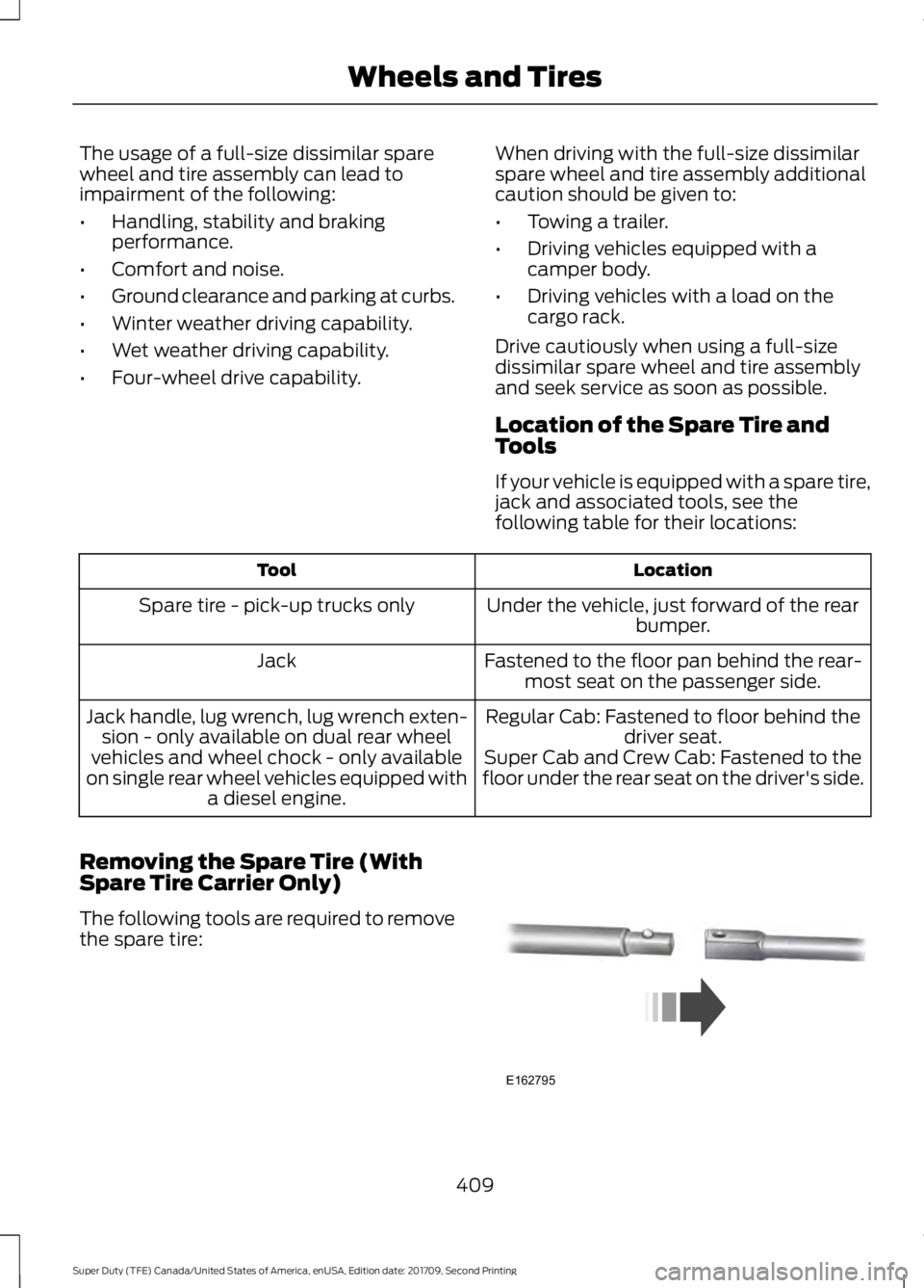
The following tools are required to remove
the spare tire: 409
Super Duty (TFE) Canada/United States of America, enUSA, Edition date: 201709, Second Printing Wheels and TiresE162795
Page 577 of 660
For a complete listing of the accessories
that are available for your vehicle, please
contact your authorized dealer or visit the
online store web site:
Web Address (United States)
www.Accessories.Ford.com Web Address (Canada)
www.Accessories.Ford.ca
Ford Custom Accessories are available for
your vehicle through an authorized dealer.
Ford Motor Company will repair or replace
any properly authorized dealer-installed
Ford Original Accessory found to be
defective in factory-supplied materials or
workmanship during the warranty period,
as well as any component damaged by the
defective accessories.
Ford Motor Company will warrant your
vehicle through the warranty that provides
the greatest benefit:
• 24 months, unlimited mileage.
• The remainder of your new vehicle
limited warranty.
Contact an authorized dealer for details
and a copy of the warranty.
Exterior style
• Commercial graphics*.
• Commercial LED warning strobe
lights*.
• Hood deflectors.
• Exhaust tip.
• Running boards.
• Side window deflectors*.
• Splash guards.
• Stainless-steel wheel covers*. •
Step bars.
• Wheel well liners.
Interior style
• Ambient lighting.
• Cargo organizers.
• Custom seat covers*.
• Floor liners.
• Floor mats.
Lifestyle
• Ash cup/smoker's package.
• Bed cargo net, tie down plates and
cleats.
• Bed extender.
• Bedliners and bedmats.
• Bed ramps.
• Hitches.
• Racks and carriers*.
• Sportliner cargo liner*.
• Tonneau/bed cover*.
• Tow hooks.
• Towing accessories.
• Trailer back-up camera.
• Trailer brake control.
• Truck bed camping tent*.
• Trailer TPMS.
Peace of mind
• Back-up alarm*.
• Bed hooks*.
• Bumper and hitch-mounted parking
sensors*.
• Ford Telematics.
• Keyless entry keypad.
• Protective seat covers*.
• Remote start and alarms.
• Roadside assistance kits*.
574
Super Duty (TFE) Canada/United States of America, enUSA, Edition date: 201709, Second Printing Accessories