2018 FORD F-450 tow
[x] Cancel search: towPage 414 of 660

WARNINGS
To help prevent your vehicle from
moving when changing a wheel, shift
the transmission into park (P), set
the parking brake and use an appropriate
block or wheel chock to secure the wheel
diagonally opposite to the wheel being
changed. For example, when changing the
front left wheel, place an appropriate block
or wheel chock on the right rear wheel. Do not get under a vehicle that is only
supported by a vehicle jack.
Do not attempt to change a tire on
the side of the vehicle close to
moving traffic. Pull far enough off the
road to avoid the danger of being hit when
operating the jack or changing the wheel. Always use the jack provided as
original equipment with your vehicle.
If using a jack other than the one
provided, make sure the jack capacity is
adequate for the vehicle weight, including
any vehicle cargo or modifications. If you
are unsure if the jack capacity is adequate,
contact the authorized dealer. Only use the spare wheel carrier to
stow the wheel provided with your
vehicle. Other wheel sizes could
cause the spare wheel carrier to fail if it
does not fit securely or is too heavy. Note:
Do not use impact tools or power
tools operating at over 200 RPM on the
spare wheel carrier winch, which may cause
it to malfunction and prevent a secure fit.
Override the winch at least three times
(there is an audible click each time) to make
sure the wheel and tire fit securely.
Note: Passengers should not remain in the
vehicle when the vehicle is being jacked.
Park on a level surface, set the parking
brake and activate the hazard flashers. 1.
Turn the engine off and block the wheel
that is diagonally opposite of the flat
tire using the wheel chock.
Note: Lock the manual hub on the wheel
if the vehicle is a 4x4.
2. Remove the jack, jack handle, lug wrench and spare tire from the
stowage locations.
3. Use the tip of the lug wrench to remove
any wheel trim.
4. Loosen each wheel lug nut ½ turn counterclockwise, but do not remove
them until the wheel is raised off the
ground.
Note: For vehicles with dual rear wheels,
insert the lug wrench extension into the lug
wrench to reach the lug nuts.
411
Super Duty (TFE) Canada/United States of America, enUSA, Edition date: 201709, Second Printing Wheels and TiresE142551
Page 416 of 660

Rear
Note:
Jack at the specified locations to
avoid damage to the vehicle.
Jacking the Vehicle 1. Turn the jack handle clockwise until
the wheel is completely off the ground
and high enough to install the spare
tire.
2. Remove the lug nuts with the lug wrench.
3. Replace the flat tire with the spare tire,
making sure the valve stem is facing
outward for all front wheels and single
rear wheel vehicles. If you are replacing
an inboard rear tire on dual rear wheel
vehicles, the valve stem must be facing
outward. If you are replacing the
outboard wheel, the valve stem must
be facing inward. Reinstall the lug nuts
until the wheel is snug against the hub.
Do not fully tighten the lug nuts until
the wheel has been lowered.
4. Lower the wheel by turning the jack handle counterclockwise.
5. Remove the jack and fully tighten the lug nuts in the order shown. See
Technical Specifications (page 418).
6. Stow the flat tire. See Stowing the flat or spare tire if the vehicle is equipped
with a spare tire carrier. 7. Stow the jack, jack handle and lug
wrench. Make sure the jack is securely
fastened so it does not rattle when
driving.
8. Unblock the wheels. 8-lug nut torque sequence
10-lug nut torque sequence
413
Super Duty (TFE) Canada/United States of America, enUSA, Edition date: 201709, Second Printing Wheels and TiresE162811 E161441
13
4
27
6
5
8 1
2
3
4
5
6
7 8
9
10
E169375 E162820
Page 417 of 660

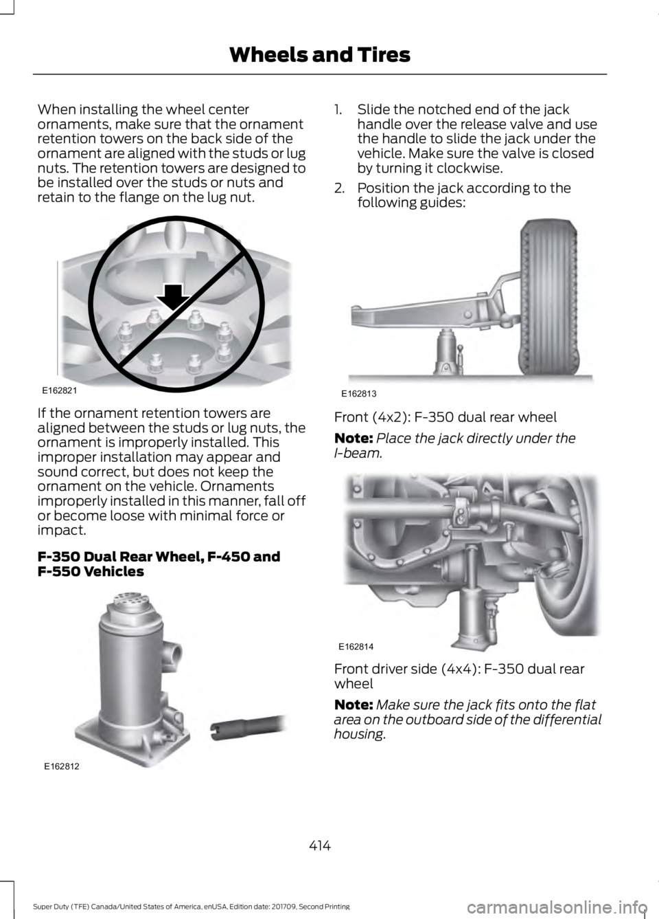
When installing the wheel center
ornaments, make sure that the ornament
retention towers on the back side of the
ornament are aligned with the studs or lug
nuts. The retention towers are designed to
be installed over the studs or nuts and
retain to the flange on the lug nut.
If the ornament retention towers are
aligned between the studs or lug nuts, the
ornament is improperly installed. This
improper installation may appear and
sound correct, but does not keep the
ornament on the vehicle. Ornaments
improperly installed in this manner, fall off
or become loose with minimal force or
impact.
F-350 Dual Rear Wheel, F-450 and
F-550 Vehicles 1. Slide the notched end of the jack
handle over the release valve and use
the handle to slide the jack under the
vehicle. Make sure the valve is closed
by turning it clockwise.
2. Position the jack according to the following guides: Front (4x2): F-350 dual rear wheel
Note:
Place the jack directly under the
I-beam. Front driver side (4x4): F-350 dual rear
wheel
Note:
Make sure the jack fits onto the flat
area on the outboard side of the differential
housing.
414
Super Duty (TFE) Canada/United States of America, enUSA, Edition date: 201709, Second Printing Wheels and TiresE162821 E162812 E162813 E162814
Page 419 of 660

2. Use an up-and-down motion with the
jack handle to raise the wheel
completely off the ground.
Note: Hydraulic jacks are equipped with a
pressure release valve that prevents lifting
loads which exceed the jack's rated
capacity.
3. Remove the lug nuts with the lug wrench.
4. Replace the flat tire with the spare tire,
making sure the valve stem is facing
outward on all front an inboard rear
wheels. If you are replacing the
outboard wheel, the valve stem must
be facing inward. Reinstall the lug nuts
until the wheel is snug against the hub.
Do not fully tighten the lug nuts until
the wheel has been lowered.
5. Lower the wheel by slowly turning the release valve counterclockwise.
Opening the release valve slowly
provides a more controlled rate of
descent.
6. Remove the jack and fully tighten the lug nuts in the order shown. See
Technical Specifications (page 418).
7. Stow the flat tire. See Stowing the flat or spare tire if the vehicle is equipped
with a spare tire carrier.
8. Stow the jack, jack handle and lug wrench. Make sure the jack is securely
fastened so it does not rattle when
driving.
9. Unblock the wheels. 8-lug nut torque sequence
10-lug nut torque sequence
Installing Dual Rear Wheel Ornaments
1. Align the ornament with the lug nuts.
A is the clip and B is the flange.
416
Super Duty (TFE) Canada/United States of America, enUSA, Edition date: 201709, Second Printing Wheels and TiresE161441
13
4
27
6
5
8 1
2
3
4
5
6
7 8
9
10
E169375 AB
E162822
Page 420 of 660

2. Hold the ornament so that all of the
retention clips are sitting on the flange
of the lug nuts. 3. Use your hand or rubber mallet to tap
the ornament in a star pattern. There
should be an even gap between the
ornament and the wheel.
4. Be sure to install all the clips on the nuts over the flanges so that there is
an even gap all around and the
retention clips are fully seated. Stowing the Flat or Spare Tire
Note:
Failure to follow spare tire stowage
instructions may result in failure of cable or
loss of spare tire.
1. Place the tire on end with the valve stem facing toward the front of the
vehicle. 417
Super Duty (TFE) Canada/United States of America, enUSA, Edition date: 201709, Second Printing Wheels and TiresE162823 A
C
B
D
E162824 E162825 E162826 E162800
Page 421 of 660

2. Lay the tire on the ground with the
valve stem facing up.
3. Slide the wheel partially under the vehicle and install the retainer through
the wheel center. Pull on the cable to
align the components at the end of the
cable.
4. Turn the jack handle clockwise until the tire is raised to its stowed position
underneath the vehicle. The effort to
turn the jack handle increases
significantly and the spare tire carrier
ratchets or slips when the tire is raised
to the maximum tightness. Tighten to
the best of your ability, to the point
where the ratchet/slip occurs, if
possible. The spare tire carrier does not
allow you to overtighten. If the spare
tire carrier ratchets or slips with little
effort, take the vehicle to your
authorized dealer for assistance at your
earliest convenience. 5. Check that the tire lies flat against the
frame and is properly tightened. Try to
push or pull, then turn the tire to be
sure it does not move. Loosen and
retighten, if necessary. Failure to
properly stow the spare tire may result
in failure of the winch cable and loss
of the tire.
6. Repeat this tightness check procedure
when servicing the spare tire pressure,
every six months, per scheduled
maintenance information, or at any
time that the spare tire is disturbed
through service of other components.
TECHNICAL SPECIFICATIONS
Wheel Lug Nut Torque Specifications WARNING
When a wheel is installed, always remove any corrosion, dirt or foreign materials
present on the mounting surfaces of the wheel or the surface of the wheel hub,
brake drum or brake disc that contacts the wheel. Make sure that any fasteners
that attach the rotor to the hub are secured so they do not interfere with the mounting
surfaces of the wheel. Installing wheels without correct metal-to-metal contact at the
wheel mounting surfaces can cause the wheel nuts to loosen and the wheel to come off
while the vehicle is in motion, resulting in loss of control. 418
Super Duty (TFE) Canada/United States of America, enUSA, Edition date: 201709, Second Printing Wheels and Tires
Page 444 of 660

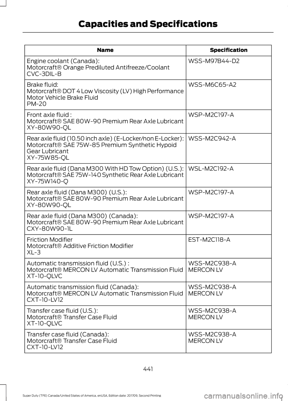
Specification
Name
WSS-M97B44-D2
Engine coolant (Canada):
Motorcraft® Orange Prediluted Antifreeze/Coolant
CVC-3DIL-B
WSS-M6C65-A2
Brake fluid:
Motorcraft® DOT 4 Low Viscosity (LV) High Performance
Motor Vehicle Brake Fluid
PM-20
WSP-M2C197-A
Front axle fluid :
Motorcraft® SAE 80W-90 Premium Rear Axle Lubricant
XY-80W90-QL
WSS-M2C942-A
Rear axle fluid (10.50 inch axle) (E-Locker/non E-Locker):
Motorcraft® SAE 75W-85 Premium Synthetic Hypoid
Gear Lubricant
XY-75W85-QL
WSL-M2C192-A
Rear axle fluid (Dana M300 With HD Tow Option) (U.S.):
Motorcraft® SAE 75W-140 Synthetic Rear Axle Lubricant
XY-75W140-Q
WSP-M2C197-A
Rear axle fluid (Dana M300) (U.S.):
Motorcraft® SAE 80W-90 Premium Rear Axle Lubricant
XY-80W90-QL
WSP-M2C197-A
Rear axle fluid (Dana M300) (Canada):
Motorcraft® SAE 80W-90 Premium Rear Axle Lubricant
CXY-80W90-1L
EST-M2C118-A
Friction Modifier
Motorcraft® Additive Friction Modifier
XL-3
WSS-M2C938-A
Automatic transmission fluid (U.S.) :
MERCON LV
Motorcraft® MERCON LV Automatic Transmission Fluid
XT-10-QLVC
WSS-M2C938-A
Automatic transmission fluid (Canada):
MERCON LV
Motorcraft® MERCON LV Automatic Transmission Fluid
CXT-10-LV12
WSS-M2C938-A
Transfer case fluid (U.S.):
MERCON LV
Motorcraft® Transfer Case Fluid
XT-10-QLVC
WSS-M2C938-A
Transfer case fluid (Canada):
MERCON LV
Motorcraft® Transfer Case Fluid
CXT-10-LV12
441
Super Duty (TFE) Canada/United States of America, enUSA, Edition date: 201709, Second Printing Capacities and Specifications
Page 448 of 660

GENERAL INFORMATION
Radio Frequencies and Reception
Factors
AM and FM frequencies are established by
the Federal Communications Commission
(FCC) and the Canadian Radio and
Telecommunications Commission (CRTC).
Those frequencies are:
•
AM: 530-1710 kHz
• FM: 87.9-107.9 MHz
Note: Listening to loud audio for long
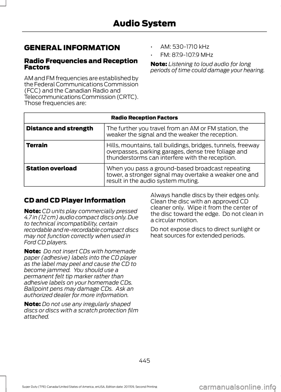
periods of time could damage your hearing. Radio Reception Factors
The further you travel from an AM or FM station, the
weaker the signal and the weaker the reception.
Distance and strength
Hills, mountains, tall buildings, bridges, tunnels, freeway
overpasses, parking garages, dense tree foliage and
thunderstorms can interfere with the reception.
Terrain
When you pass a ground-based broadcast repeating
tower, a stronger signal may overtake a weaker one and
result in the audio system muting.
Station overload
CD and CD Player Information
Note: CD units play commercially pressed
4.7 in (12 cm) audio compact discs only. Due
to technical incompatibility, certain
recordable and re-recordable compact discs
may not function correctly when used in
Ford CD players.
Note: Do not insert CDs with homemade
paper (adhesive) labels into the CD player
as the label may peel and cause the CD to
become jammed. You should use a
permanent felt tip marker rather than
adhesive labels on your homemade CDs.
Ballpoint pens may damage CDs. Ask an
authorized dealer for more information.
Note: Do not use any irregularly shaped
discs or discs with a scratch protection film
attached. Always handle discs by their edges only.
Clean the disc with an approved CD
cleaner only. Wipe it from the center of
the disc toward the edge. Do not clean in
a circular motion.
Do not expose discs to direct sunlight or
heat sources for extended periods.
445
Super Duty (TFE) Canada/United States of America, enUSA, Edition date: 201709, Second Printing Audio System