2018 FORD F-450 light
[x] Cancel search: lightPage 258 of 660

Setting up a Blind Spot Trailer
Trailer length
A
Trailer width
B
Trailer hitch ball
C
You can set-up any trailer to work with the
Blind Spot Information System with Trailer
Tow through the instrument cluster menu.
See General Information (page 113).
While setting up a trailer, a sequence of
screens appear asking for trailer
information. The Blind Spot Information
System with Trailer Tow specific screens
are described below:
• Select type of trailer screen -
Conventional, fifth wheel or gooseneck.
The Blind Spot Information System with
Trailer Tow only supports conventional
trailers. If fifth wheel or gooseneck is
selected, the system automatically turns
off.
• Do you want to set up BLIS with trailer
screen?
If no, the Blind Spot Information System
turns off.
If yes, the menu goes to the next screen.
• Is the width less than
9 ft (2.7 m) and
length less than 33 ft (10.1 m)?
If no, the Blind Spot Information System
turns off.
If yes, the menu goes to the next screen.
• Trailer width measurement: The width of the trailer is measured at the
front of the trailer. It is not measured at the
widest point of the trailer. The maximum
width at the front of the trailer that the
Blind Spot Information System with Trailer
Tow can support is
8.5 ft (2.6 m).
Note: You do not need to enter an exact
trailer width measurement; just measure
that it is
8.5 ft (2.6 m) or less.
• Trailer length measurement:
The trailer length is the distance between
the trailer hitch ball and the rear of the
trailer. The maximum length that the Blind
Spot Information System with Trailer Tow
can support is
33 ft (10.1 m).
• Enter length of trailer:
The default setting is
18 ft (5.5 m).
Toggling up or down using the menu
buttons will increase/decrease the
measurement by
3 ft (1 m). Select the
length so that the value is equal to or
within
3 ft (1 m) of the actual measured
length. For example, if the actual measured
length is
25 ft (7.6 m), then toggle the
length in the menu to 27 ft (8.2 m). When
the length has been entered, the Blind Spot
Information System with Trailer Tow setup
is saved.
If you do not set up a Blind Spot Trailer, a
warning appears in the instrument cluster
when a trailer is connected stating that the
system has been turned off due to a trailer
connect.
Note: If the trailer is actually a bike rack or
cargo rack with electrical lighting, then the
length will be
3 ft (1 m). Cross Traffic Alert
will remain on for trailers 3 ft (1 m) or less.
Note: Proper measurement and
measurement entry is required for Blind
Spot Information System with Trailer Tow
to function as designed.
255
Super Duty (TFE) Canada/United States of America, enUSA, Edition date: 201709, Second Printing Driving AidsE225008
Page 259 of 660

System Operation
If you select a trailer in the display screen
prior to connecting the trailer, the system
will load that configuration and the
information cluster displays a message
when the trailer is connected. A second
message appears stating Cross Traffic
Alert has been turned off; the Blind Spot
Information System with Trailer Tow still
functions normally when driving forward.
If no trailer has been set up and a trailer is
connected, the instrument cluster provides
a message indicating a trailer is connected
followed by a message asking to select a
trailer from the existing list of trailers or to
add a trailer. In order for the Blind Spot
Information System with Trailer Tow to
function, an existing trailer must be
selected or a new trailer must be added. If
the request is ignored or if you exit the
screen, a message appears prompting you
that the system has been turned off due
to a trailer connect. This message may not
appear until your vehicle speed reaches
22 mph (35 km/h).
The Blind Spot Information System with
Trailer Tow activates when driving forward
for that particular trailer set up. If the
ignition is cycled, the Blind Spot
Information System with Trailer Tow
continues to function using the last trailer
selected.
Trailer Considerations
The Blind Spot Information System with
Trailer Tow is designed to work with any
trailer whose front width is
8.5 ft (2.6 m)
or less and total length from the trailer
hitch ball to the rear of the trailer is
33 ft
(10.1 m) or less. Different trailers may
cause a slight change in performance as
outlined below. Large box trailers may cause false alerts
to trigger when driving next to buildings or
near parking cars. A false alert may also
occur while making a 90-degree turn.
Trailers that are
8.5 ft (2.6 m) wide at the
front and have a total length greater than
20 ft (6 m)
may have delayed alerts from
passing vehicles when the vehicle is
passing at high speed.
A box trailer whose front width is
8.5 ft
(2.6 m) may cause early alerts when you
are over taking a vehicle.
When towing a clam shell or V-Nose box
trailer with a front width of
8.5 ft (2.6 m),
delayed alerts on merging vehicles that are
traveling the same speed as your vehicle
may occur.
System Errors
If the system senses a problem with the
left or right sensor, the telltale illuminates
and a message appears in the display
screen. See
Information Messages
(page 129).
Switching the System Off and On
You can temporarily switch the Blind Spot
Information System off in the display
screen. See
General Information (page
113). When the Blind Spot Information
System switches off, you do not receive
alerts and the display screen shows a
system off message. The telltale in the
cluster also illuminates. When you switch
the Blind Spot Information System on or
off, the alert indicators flash twice.
Note: The Blind Spot Information System
remembers the last selected on or off
setting.
You can also have the Blind Spot
Information System switched off
permanently at an authorized dealer. Once
switched off permanently, the system can
only be switched back on at an authorized
dealer.
256
Super Duty (TFE) Canada/United States of America, enUSA, Edition date: 201709, Second Printing Driving Aids
Page 261 of 660

System Lights, Messages and
Audible Alerts
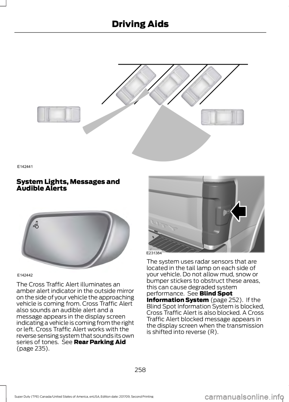
The Cross Traffic Alert illuminates an
amber alert indicator in the outside mirror
on the side of your vehicle the approaching
vehicle is coming from. Cross Traffic Alert
also sounds an audible alert and a
message appears in the display screen
indicating a vehicle is coming from the right
or left. Cross Traffic Alert works with the
reverse sensing system that sounds its own
series of tones. See Rear Parking Aid
(page 235). The system uses radar sensors that are
located in the tail lamp on each side of
your vehicle. Do not allow mud, snow or
bumper stickers to obstruct these areas,
this can cause degraded system
performance. See
Blind Spot
Information System (page 252). If the
Blind Spot Information System is blocked,
Cross Traffic Alert is also blocked. A Cross
Traffic Alert blocked message appears in
the display screen when the transmission
is shifted into reverse (R).
258
Super Duty (TFE) Canada/United States of America, enUSA, Edition date: 201709, Second Printing Driving AidsE142441 E142442 E231384
Page 264 of 660

COLLISION WARNING SYSTEM
(If Equipped)
Principle Of Operation (If Equipped)
WARNINGS
This system is an extra driving aid. It
does not replace your attention and
judgment, or the need to apply the
brakes. This system does NOT
automatically brake your vehicle. If you fail
to press the brake pedal when necessary,
you may collide with another vehicle. The collision warning system with
brake support cannot help prevent
all collisions. Do not rely on this
system to replace your judgment and the
need to maintain correct distance and
speed. Note:
The system does not detect, warn or
respond to potential collisions with vehicles
to the rear or sides of your vehicle.
Note: The collision warning system is active
at speeds above approximately
5 mph
(8 km/h).
Note: The collision warning system will be
unavailable if you disable the electronic
stability control. See
Using Stability
Control (page 231). The system alerts you of certain collision
risks. The system's sensor detects your
vehicle's rapid approach to other vehicles
traveling in the same direction as your
vehicle. When your vehicle rapidly approaches
another vehicle, a red warning light flashes
and a tone sounds.
The brake support system assists you in
reducing any collision speed by
pre-charging the brakes. If the risk of
collision continues to increases after the
audio-visual warning, the brake support
prepares the brake system for rapid
braking. The system does not
automatically activate the brakes, but if
the brake pedal is pressed even lightly, the
brakes apply full stopping power.
Using the Collision Warning System
WARNING
The collision warning system
’s brake
support reduces collision speed only
if you brake your vehicle before any
collision. As in any typical braking situation,
you must press your brake pedal. You can use your information display
control to adjust the collision warning
system's sensitivity or to turn the system
On or Off. Your vehicle will remember
these settings across key cycles. You may
change the collision warning system
sensitivity to any one of three possible
settings. See General Information (page
113
).
261
Super Duty (TFE) Canada/United States of America, enUSA, Edition date: 201709, Second Printing Driving AidsE156130 E156131
Page 276 of 660

Load Placement
To help minimize how trailer
movement affects your vehicle
when driving:
•
Load the heaviest items closest
to the trailer floor.
• Load the heaviest items
centered between the left and
right side trailer tires.
• Load the heaviest items above
the trailer axles or just slightly
forward toward the trailer
tongue. Do not allow the final
trailer tongue weight to go
above or below 10-15% of the
loaded trailer weight.
• Select a ball mount with the
correct rise or drop. When both
the loaded vehicle and trailer
are connected, the trailer frame
should be level, or slightly
angled down toward your
vehicle, when viewed from the
side. When driving with a trailer or
payload, a slight takeoff vibration
or shudder may be present due to
the increased payload weight.
Additional information regarding
proper trailer loading and setting
your vehicle up for towing is
located in another chapter of this
manual. See Load Limit (page
264).
You can also find information in
the
RV & Trailer Towing Guide
available at your authorized
dealer, or online. RV & Trailer Towing Guide Online
http://www.fleet.ford.com/towing-guides/
Website
273
Super Duty (TFE) Canada/United States of America, enUSA, Edition date: 201709, Second Printing Towing
Page 285 of 660

Note:
In some cases, if vehicle speed is too
high, the system may activate multiple
times, gradually reducing vehicle speed.
This feature applies your vehicle brakes at
individual wheels and, if necessary, reduces
engine power. If the trailer begins to sway,
the stability control light flashes and the
message TRAILER SWAY REDUCE
SPEED appears in the information display.
The first thing to do is slow your vehicle
down, then pull safely to the side of the
road and check for proper tongue load and
trailer load distribution. See
Load
Carrying (page 264).
RECOMMENDED TOWING
WEIGHTS WARNING
You must use the heavy-duty
drawbar pin supplied with
your vehicle when using the
heavy-duty hitch. Failure to follow
this instruction could result in the
loss of control of your vehicle,
personal injury or death. Note:
Vehicles with a heavy-duty
hitch must use the drawbar pin
stamped 21,000 LBS. You can
obtain a replacement drawbar pin
at your authorized dealer. Note:
Make sure to take into
consideration trailer frontal area.
Do not exceed 60 ft 2
(5.6 m 2
) trailer
frontal area for conventional
trailers. Do not exceed 75 ft 2
(6.9
m 2
) trailer frontal area for fifth
wheel and gooseneck trailers.
Note: Exceeding this limitation
may significantly reduce the
performance of your towing
vehicle. Selecting a trailer with a
low aerodynamic drag and rounded
front design helps optimize
performance and fuel economy.
Note: For high altitude operation,
reduce the gross combined weight
by 2% per
1,000 ft (300 m)
starting at the 1,000 ft (300 m)
elevation point.
Note: Certain states require
electric trailer brakes for trailers
over a specified weight. Be sure to
check state regulations for this
specified weight. The maximum
trailer weights listed may be limited
to this specified weight, as your
vehicle's electrical system may not
include the wiring connector
needed to use electric trailer
brakes.
Your vehicle may tow a trailer
provided the maximum trailer
weight is less than or equal to the
maximum trailer weight
calculated using the formula
following the chart.
282
Super Duty (TFE) Canada/United States of America, enUSA, Edition date: 201709, Second Printing Towing
Page 289 of 660

ESSENTIAL TOWING CHECKS
WARNING
Do not exceed the maximum vertical
load on the tow ball. Failure to follow
this instruction could result in the
loss of control of your vehicle, personal
injury or death. Follow these guidelines for safe towing:
•
Do not tow a trailer until you drive your
vehicle at least 1,000 mi (1,600 km).
• Consult your local motor vehicle laws
for towing a trailer.
• See the instructions included with
towing accessories for the proper
installation and adjustment
specifications.
• Service your vehicle more frequently if
you tow a trailer. See your scheduled
maintenance information.
See
Scheduled Maintenance (page 581).
• If you use a rental trailer, follow the
instructions the rental agency gives
you.
See
Load Limits in the Load Carrying
chapter for load specification terms found
on the tire label and Safety Compliance
label and instructions on calculating your
vehicle's load.
Vehicles with a diesel engine have an
engine braking feature.
See General
Information (page 225).
Remember to account for the trailer
tongue weight as part of your vehicle load
when calculating the total vehicle weight.
Some vehicles will have the ability to
modify trailer towing features. See
General Information
(page 113). Trailer Towing Connector
When attaching the trailer wiring connector
to your vehicle, only use a proper fitting
connector that works with the vehicle and
trailer functions. Some seven-position
connectors may have the SAE J2863 logo,
which confirms that it is the proper wiring
connector and works correctly with your
vehicle.
Function
Color
Left turn signal and stop lamp
Yellow
Ground (-)
White
Electric brakes
Blue
Right turn signal and stop
lamp
Green
Battery (+)
Orange
Running lights
Brown
Reverse lights
Grey
286
Super Duty (TFE) Canada/United States of America, enUSA, Edition date: 201709, Second Printing TowingE163167
Page 292 of 660

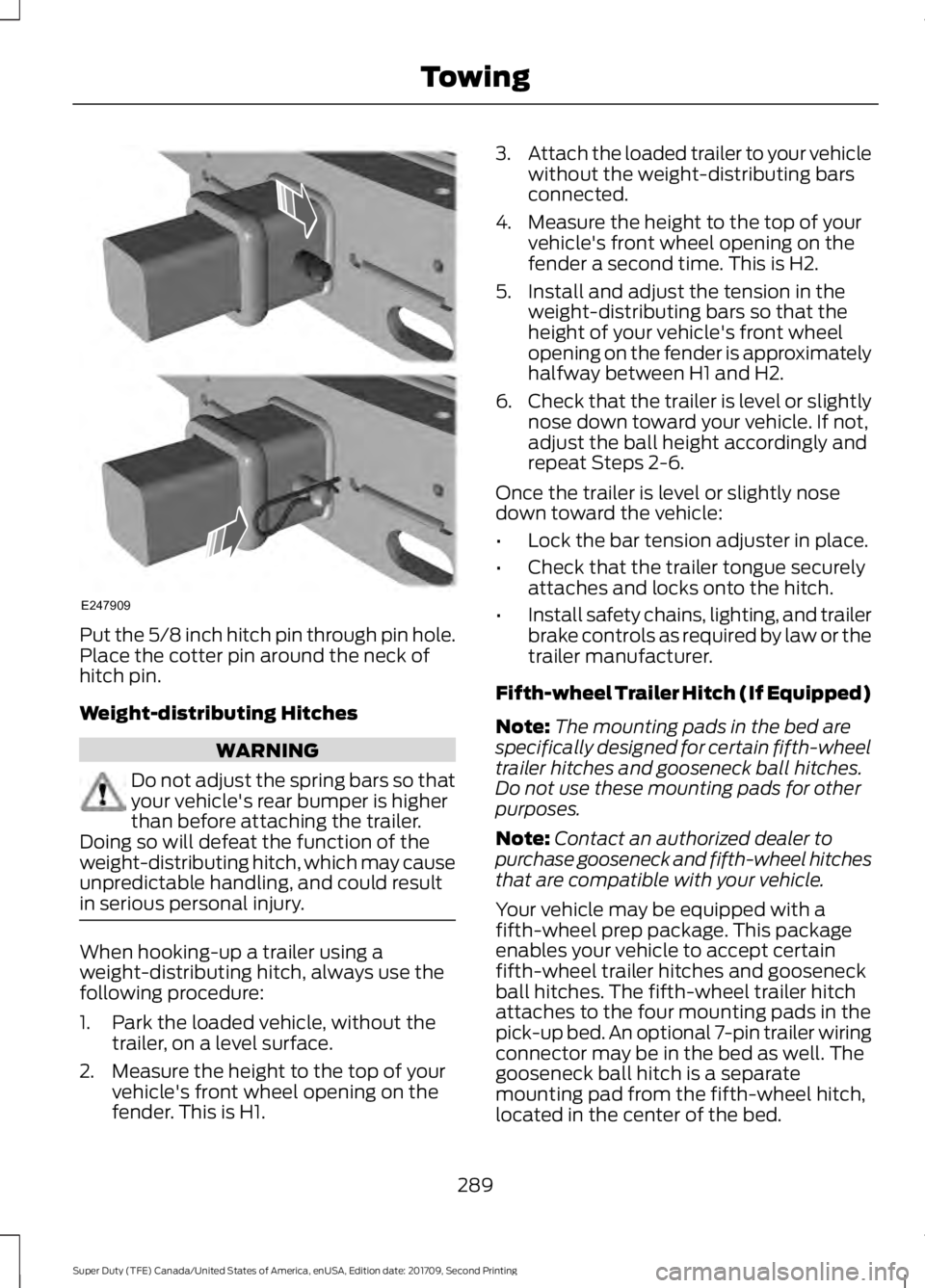
Put the 5/8 inch hitch pin through pin hole.
Place the cotter pin around the neck of
hitch pin.
Weight-distributing Hitches
WARNING
Do not adjust the spring bars so that
your vehicle's rear bumper is higher
than before attaching the trailer.
Doing so will defeat the function of the
weight-distributing hitch, which may cause
unpredictable handling, and could result
in serious personal injury. When hooking-up a trailer using a
weight-distributing hitch, always use the
following procedure:
1. Park the loaded vehicle, without the
trailer, on a level surface.
2. Measure the height to the top of your vehicle's front wheel opening on the
fender. This is H1. 3.
Attach the loaded trailer to your vehicle
without the weight-distributing bars
connected.
4. Measure the height to the top of your vehicle's front wheel opening on the
fender a second time. This is H2.
5. Install and adjust the tension in the weight-distributing bars so that the
height of your vehicle's front wheel
opening on the fender is approximately
halfway between H1 and H2.
6. Check that the trailer is level or slightly
nose down toward your vehicle. If not,
adjust the ball height accordingly and
repeat Steps 2-6.
Once the trailer is level or slightly nose
down toward the vehicle:
• Lock the bar tension adjuster in place.
• Check that the trailer tongue securely
attaches and locks onto the hitch.
• Install safety chains, lighting, and trailer
brake controls as required by law or the
trailer manufacturer.
Fifth-wheel Trailer Hitch (If Equipped)
Note: The mounting pads in the bed are
specifically designed for certain fifth-wheel
trailer hitches and gooseneck ball hitches.
Do not use these mounting pads for other
purposes.
Note: Contact an authorized dealer to
purchase gooseneck and fifth-wheel hitches
that are compatible with your vehicle.
Your vehicle may be equipped with a
fifth-wheel prep package. This package
enables your vehicle to accept certain
fifth-wheel trailer hitches and gooseneck
ball hitches. The fifth-wheel trailer hitch
attaches to the four mounting pads in the
pick-up bed. An optional 7-pin trailer wiring
connector may be in the bed as well. The
gooseneck ball hitch is a separate
mounting pad from the fifth-wheel hitch,
located in the center of the bed.
289
Super Duty (TFE) Canada/United States of America, enUSA, Edition date: 201709, Second Printing TowingE247909