2018 FORD F-250 four wheel drive
[x] Cancel search: four wheel drivePage 398 of 660

U.S. DOT Tire Identification
Number
Both United States and Canada
Federal regulations require tire
manufacturers to place
standardized information on the
sidewall of all tires. This
information identifies and
describes the fundamental
characteristics of the tire and also
provides a U.S. DOT Tire
Identification Number for safety
standard certification and in case
of a recall.
This begins with the letters DOT
and indicates that the tire meets
all federal standards. The next
two numbers or letters are the
plant code designating where it
was manufactured, the next two
are the tire size code and the last
four numbers represent the week
and year the tire was built. For
example, the numbers 317 mean
the 31st week of 1997. After 2000
the numbers go to four digits. For
example, 2501 means the 25th
week of 2001. The numbers in
between are identification codes
used for traceability. This
information is used to contact
customers if a tire defect requires
a recall.
Tire Replacement
Requirements
Your vehicle is equipped with tires
designed to provide a safe ride
and handling capability.
WARNINGS
Only use replacement tires
and wheels that are the same
size, load index, speed rating and
type (such as P-metric versus
LT-metric or all-season versus
all-terrain) as those originally
provided by Ford. The
recommended tire and wheel size
may be found on either the Safety
Compliance Certification Label
(affixed to either the door hinge
pillar, door-latch post, or the door
edge that meets the door-latch
post, next to the driver ’s seating
position), or the Tire Label which
is located on the B-Pillar or edge
of the driver ’s door. If this
information is not found on these
labels, then you should contact
your authorized dealer as soon as
possible. Use of any tire or wheel
not recommended by Ford can
affect the safety and performance
of your vehicle, which could result
in an increased risk of loss of
vehicle control, vehicle rollover,
personal injury and death. To reduce the risk of serious
injury, when mounting
replacement tires and wheels, you
should not exceed the maximum
pressure indicated on the sidewall
of the tire to set the beads without
additional precautions listed
below. If the beads do not seat at
the maximum pressure indicated,
re-lubricate and try again.
395
Super Duty (TFE) Canada/United States of America, enUSA, Edition date: 201709, Second Printing Wheels and Tires
Page 400 of 660

Safety Practices
WARNINGS
If your vehicle is stuck in
snow, mud or sand, do not
rapidly spin the tires; spinning the
tires can tear the tire and cause
an explosion. A tire can explode in
as little as three to five seconds. Do not spin the wheels at
over 34 mph (55 km/h). The
tires may fail and injure a
passenger or bystander. Driving habits have a great deal
to do with your tire mileage and
safety.
*Observe posted speed limits.
*Avoid fast starts, stops and turns.
*Avoid potholes and objects on
the road.
*Do not run over curbs or hit the
tire against a curb when parking.
Highway Hazards
No matter how carefully you drive
there
’s always the possibility that
you may eventually have a flat tire
on the highway. Drive slowly to the
closest safe area out of traffic.
This may further damage the flat
tire, but your safety is more
important. If you feel a sudden vibration or
ride disturbance while driving, or
you suspect your tire or vehicle
has been damaged, immediately
reduce your speed. Drive with
caution until you can safely pull
off the road. Stop and inspect the
tires for damage. If a tire is
under-inflated or damaged,
deflate it, remove wheel and
replace it with your spare tire and
wheel. If you cannot detect a
cause, have the vehicle towed to
the nearest repair facility or tire
dealer to have the vehicle
inspected.
Tire and Wheel Alignment
A bad jolt from hitting a curb or
pothole can cause the front end
of your vehicle to become
misaligned or cause damage to
your tires. If your vehicle seems to
pull to one side when you’re
driving, the wheels may be out of
alignment. Have an authorized
dealer check the wheel alignment
periodically.
Wheel misalignment in the front
or the rear can cause uneven and
rapid treadwear of your tires and
should be corrected by an
authorized dealer. Front-wheel
drive vehicles and those with an
independent rear suspension may
require alignment of all four
wheels.
The tires should also be balanced
periodically. An unbalanced tire
and wheel assembly may result in
irregular tire wear.
397
Super Duty (TFE) Canada/United States of America, enUSA, Edition date: 201709, Second Printing Wheels and Tires
Page 401 of 660

Tire Rotation
WARNING
If the tire label shows
different tire pressures for the
front and rear tires and the vehicle
has a tire pressure monitoring
system, then you need to update
the settings for the system
sensors. Always perform the
system reset procedure after tire
rotation. If you do not reset the
system, it may not provide a low
tire pressure warning when
necessary. Note:
If your tires show uneven
wear ask an authorized dealer to
check for and correct any wheel
misalignment, tire imbalance or
mechanical problem involved
before tire rotation.
Note: Your vehicle may be
equipped with a dissimilar spare
wheel and tire assembly. A
dissimilar spare wheel and tire
assembly is defined as a spare
wheel and tire assembly that is
different in brand, size or
appearance from the road tires and
wheels. If you have a dissimilar
spare wheel and tire assembly it is
intended for temporary use only
and should not be used in a tire
rotation.
Note: After having your tires
rotated, inflation pressure must be
checked and adjusted to the
vehicle requirements. Rotating your tires at the
recommended interval (as
indicated in the Scheduled
Maintenance chapter) will help
your tires wear more evenly,
providing better tire performance
and longer tire life. Sometime
irregular tire wear can be
corrected by rotating the tires.
Rear-wheel drive vehicles and
four-wheel drive vehicles (front
tires at left of diagram).
398
Super Duty (TFE) Canada/United States of America, enUSA, Edition date: 201709, Second Printing Wheels and TiresE142548
Page 408 of 660

•
To reduce the chances of interference
from another vehicle, perform the
system reset procedure at least three
feet (one meter) away from another
Ford Motor Company vehicle
undergoing the system reset procedure
at the same time.
• Do not wait more than two minutes
between resetting each tire sensor or
the system will time-out and the entire
procedure will have to be repeated on
all four wheels.
• A double horn will sound indicating the
need to repeat the procedure.
Performing the System Reset Procedure
(Single Rear Wheel)
Read the entire procedure before
attempting.
1. Drive the vehicle above 20 mph
(32 km/h) for at least two minutes,
then park in a safe location where you
can easily get to all four tires and have
access to an air pump.
2. Place the ignition in the off position and
keep the key in the ignition.
3. Cycle the ignition to the on position with the engine off.
4. Turn the hazard flashers on then off three times. You must accomplish this
within 10 seconds. If the reset mode
has been entered successfully, the horn
will sound once, the system indicator
will flash and a message is shown in
the information display. If this does not
occur, please try again starting at Step
2. If after repeated attempts to enter
the reset mode, the horn does not
sound, the system indicator does not
flash and no message is shown in the
information display, seek service from
your authorized dealer. 5. Train the tire pressure monitoring
system sensors in the tires using the
following system reset sequence
starting with the left front tire in the
following clockwise order: Left front
(driver's side front tire), Right front
(passenger's side front tire), Right rear
(passenger's side rear tire), Left rear
(driver's side rear tire).
6. Remove the valve cap from the valve stem on the left front tire. Decrease the
air pressure until the horn sounds.
Note: The single horn chirp confirms that
the sensor identification code has been
learned by the module for this position. If a
double horn is heard, the reset procedure
was unsuccessful, and you must repeat it.
7. Remove the valve cap from the valve stem on the right front tire. Decrease
the air pressure until the horn sounds.
8. Remove the valve cap from the valve stem on the right rear tire. Decrease the
air pressure until the horn sounds.
9. Remove the valve cap from the valve stem on the left rear tire. Decrease the
air pressure until the horn sounds.
Training is complete after the horn
sounds for the last tire trained (driver's
side rear tire), the system indicator
stops flashing, and a message is shown
in the information display.
10. Turn the ignition off. If two short horn
beeps are heard, the reset procedure
was unsuccessful and you must
repeat it. If after repeating the
procedure and two short beeps are
heard when the ignition is turned to
off, seek assistance from your
authorized dealer.
405
Super Duty (TFE) Canada/United States of America, enUSA, Edition date: 201709, Second Printing Wheels and Tires
Page 409 of 660

11.
Set all four tires to the recommended
air pressure as indicated on the
Safety Compliance Certification
Label (affixed to either the door hinge
pillar, door-latch post, or the door
edge that meets the door-latch post,
next to the driver's seating position)
or Tire Label located on the B-Pillar
or the edge of the driver's door.
Performing the System Reset Procedure
(Dual Rear Wheel)
For further information see
Understanding Your Tire Pressure
Monitoring System and refer to Dual
Rear Wheel, earlier in this section.
Read the entire procedure before
attempting.
1. Drive the vehicle above
20 mph
(32 km/h) for at least two minutes,
then park in a safe location where you
can easily get to all six tires and have
access to an air pump.
2. Place the ignition in the off position and
keep the key in the ignition.
3. Cycle the ignition to the on position with the engine off.
4. Turn the hazard flashers on then off three times. You must accomplish this
within 10 seconds. If the reset mode
has been entered successfully, the horn
will sound once, the system indicator
will flash and a message is shown in
the information display. If this does not
occur, please try again starting at Step
2. If after repeated attempts to enter
the reset mode, the horn does not
sound, the system indicator does not
flash and no message is shown in the
information display, seek service from
your authorized dealer. 5. Train the tire pressure monitoring
system sensors in the tires using the
following system reset sequence
starting with the left front tire in the
following order: Left front (driver's side
front tire), Right front (passenger's side
front tire), Right outer rear (passenger's
side rear outer tire), Right inner rear
(passenger's side rear inner tire), Left
outer rear (driver's side rear outer tire),
Left inner rear (driver's side rear inner
tire).
6. Remove the valve cap from the valve stem on the left front tire. Decrease the
air pressure until the horn sounds.
Note: The single horn chirp confirms that
the sensor identification code has been
learned by the module for this position. If a
double horn is heard, the reset procedure
was unsuccessful, and you must repeat it.
7. Remove the valve cap from the valve stem on the right front tire. Decrease
the air pressure until the horn sounds.
8. Remove the valve cap from the valve stem on the right outer rear tire.
Decrease the air pressure until the horn
sounds.
9. Remove the valve cap from the valve stem on the right inner rear tire.
Decrease the air pressure until the horn
sounds.
10. Remove the valve cap from the valve
stem on the left outer rear tire.
Decrease the air pressure until the
horn sounds.
11. Remove the valve cap from the valve
stem on the left inner rear tire.
Decrease the air pressure until the
horn sounds. Training is complete
after the horn sounds for the last tire
trained, the system indicator stops
flashing, and a message is shown in
the information display.
406
Super Duty (TFE) Canada/United States of America, enUSA, Edition date: 201709, Second Printing Wheels and Tires
Page 412 of 660

The usage of a full-size dissimilar spare
wheel and tire assembly can lead to
impairment of the following:
•
Handling, stability and braking
performance.
• Comfort and noise.
• Ground clearance and parking at curbs.
• Winter weather driving capability.
• Wet weather driving capability.
• Four-wheel drive capability. When driving with the full-size dissimilar
spare wheel and tire assembly additional
caution should be given to:
•
Towing a trailer.
• Driving vehicles equipped with a
camper body.
• Driving vehicles with a load on the
cargo rack.
Drive cautiously when using a full-size
dissimilar spare wheel and tire assembly
and seek service as soon as possible.
Location of the Spare Tire and
Tools
If your vehicle is equipped with a spare tire,
jack and associated tools, see the
following table for their locations: Location
Tool
Under the vehicle, just forward of the rearbumper.
Spare tire - pick-up trucks only
Fastened to the floor pan behind the rear-most seat on the passenger side.
Jack
Regular Cab: Fastened to floor behind thedriver seat.
Jack handle, lug wrench, lug wrench exten-
sion - only available on dual rear wheel
vehicles and wheel chock - only available
on single rear wheel vehicles equipped with a diesel engine. Super Cab and Crew Cab: Fastened to the
floor under the rear seat on the driver's side.
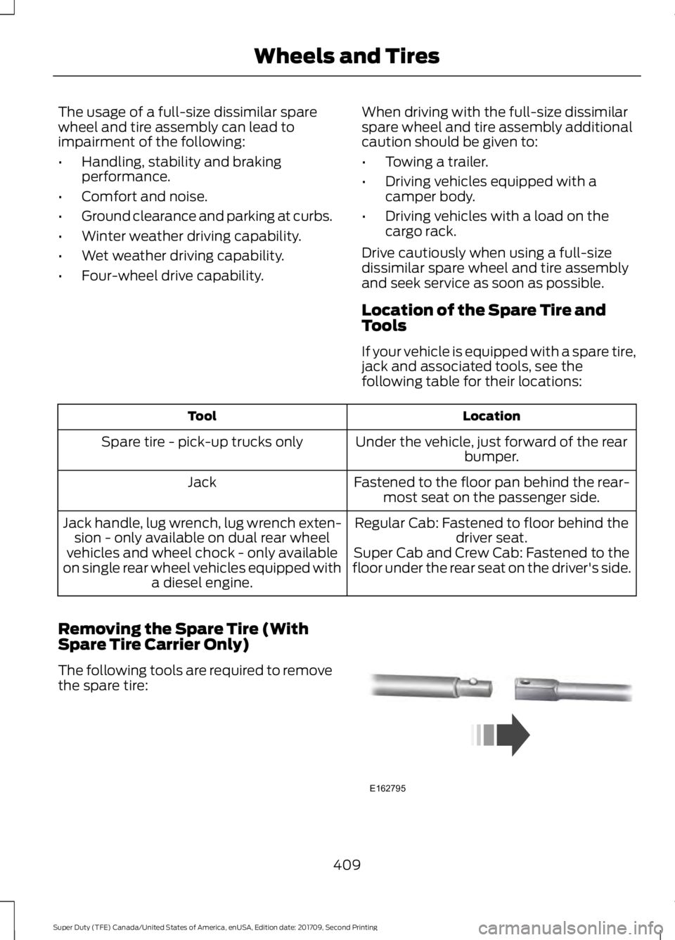
Removing the Spare Tire (With
Spare Tire Carrier Only)
The following tools are required to remove
the spare tire: 409
Super Duty (TFE) Canada/United States of America, enUSA, Edition date: 201709, Second Printing Wheels and TiresE162795
Page 588 of 660

Gasoline Engine
Normal Maintenance Intervals
7,500 mi (12,000 km) or Six Months Whichever Comes First
Change engine oil and filter.
Rotate tires 1
, inspect tire wear and measure tread depth.
Inspect wheels and related components for abnormal noise, wear, looseness or drag.
Perform multi-point inspection recommended.
1 Vehicles with dual rear wheels should rotate the front wheels when specified; rear wheels
only if unusual wear is noted. 15,000 mi (24,000 km) or 12 Months Whichever Comes First
Inspect automatic transmission fluid level. Consult dealer for requirements.
Inspect brake pads, shoes, rotors, drums, brake linings, hoses and parking brake.
Inspect engine coolant concentration, freeze-point protection, level and hoses.
Inspect exhaust system and heat shields.
Inspect front axle and U-joints. Lubricate if equipped with grease fittings. Four-wheel
drive vehicles.
Inspect steering linkage, ball joints, suspension, tie-rod ends, driveshaft and U-joints.
Lubricate if equipped with grease fittings. Other Maintenance Items
Replace cabin air filter.
Every 15,000 mi
(24,000 km)
Replace engine air filter.
Every
30,000 mi
(48,000 km)
Replace front wheel bearing grease and grease seal if non-
sealed bearings are used.
Every
60,000 mi
(96,000 km)
Replace spark plugs.
Every
97,000 mi
(156,000 km)
Change engine coolant.1
Every
105,000 mi
(168,000 km)
585
Super Duty (TFE) Canada/United States of America, enUSA, Edition date: 201709, Second Printing Scheduled Maintenance
Page 591 of 660

At Every Oil Change Interval as Indicated by the Information Display
1
Inspect the front axle and U-joints. Lubricate any grease fittings. Four-wheel drive
vehicles.
Inspect the steering linkage, ball joints, suspension, tie-rod ends, driveshaft and U-joints.
Lubricate any grease fittings.
1 Do not exceed one year or 10,000 mi (16,000 km) between service intervals.
2 Reset the Intelligent Oil-Life Monitor after engine oil and filter changes.
3 Vehicles with dual rear wheels should rotate the front wheels when specified; rear wheels
only if unusual wear is noted. Other maintenance items
1
Replace the cabin air filter.
Every
20,000 mi
(32,000 km)
Replace the engine-mounted and frame-mounted fuel
filters.
Every
30,000 mi
(48,000 km) Inspect the engine and secondary cooling system coolant
concentration freeze-point protection, additive corrosion
inhibitor strength, coolant level, and hoses. Add coolant
additive if necessary.
Replace the air inlet foam filter.
Every
45,000 mi
(72,000 km)
Replace the front wheel bearing grease and grease seal
if using non-sealed bearings. Two-wheel drive vehicles.
Every
60,000 mi
(96,000 km)
Inspect the accessory drive belt or belts. 2
At
90,000 mi (144,000 km)
Change the crankcase ventilation filter element if
equipped. Dual rear wheel and incomplete chassis
configurations only.
Every
100,000 mi
(160,000 km)
Change the engine and secondary cooling system coolant. 3
Change the automatic transmission fluid and filter. Consult
dealer for requirements.
Every
150,000 mi
(240,000 km) Replace the accessory drive belt or belts if not replaced
within the last 100,000 mi (160,000 km)
Replace the front wheel bearings and seals if using non-
sealed bearings. Two-wheel drive vehicles.
588
Super Duty (TFE) Canada/United States of America, enUSA, Edition date: 201709, Second Printing Scheduled Maintenance