2018 FORD EXPEDITION Center high mount
[x] Cancel search: Center high mountPage 265 of 571

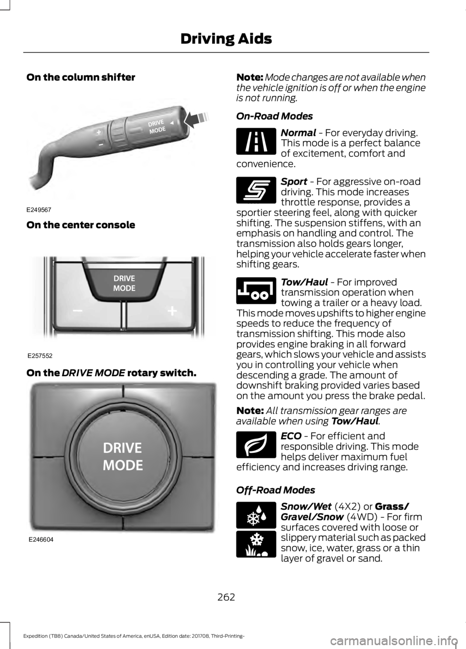
On the column shifter
On the center console
On the DRIVE MODE rotary switch. Note:
Mode changes are not available when
the vehicle ignition is off or when the engine
is not running.
On-Road Modes Normal
- For everyday driving.
This mode is a perfect balance
of excitement, comfort and
convenience. Sport
- For aggressive on-road
driving. This mode increases
throttle response, provides a
sportier steering feel, along with quicker
shifting. The suspension stiffens, with an
emphasis on handling and control. The
transmission also holds gears longer,
helping your vehicle accelerate faster when
shifting gears. Tow/Haul
- For improved
transmission operation when
towing a trailer or a heavy load.
This mode moves upshifts to higher engine
speeds to reduce the frequency of
transmission shifting. This mode also
provides engine braking in all forward
gears, which slows your vehicle and assists
you in controlling your vehicle when
descending a grade. The amount of
downshift braking provided varies based
on the amount you press the brake pedal.
Note: All transmission gear ranges are
available when using
Tow/Haul. ECO
- For efficient and
responsible driving. This mode
helps deliver maximum fuel
efficiency and increases driving range.
Off-Road Modes Snow/Wet
(4X2) or Grass/
Gravel/Snow (4WD) - For firm
surfaces covered with loose or
slippery material such as packed
snow, ice, water, grass or a thin
layer of gravel or sand.
262
Expedition (TB8) Canada/United States of America, enUSA, Edition date: 201708, Third-Printing- Driving AidsE249567 E257552 E246604 E225310 E246593 E246592 E246597 E225312 E246594
Page 270 of 571

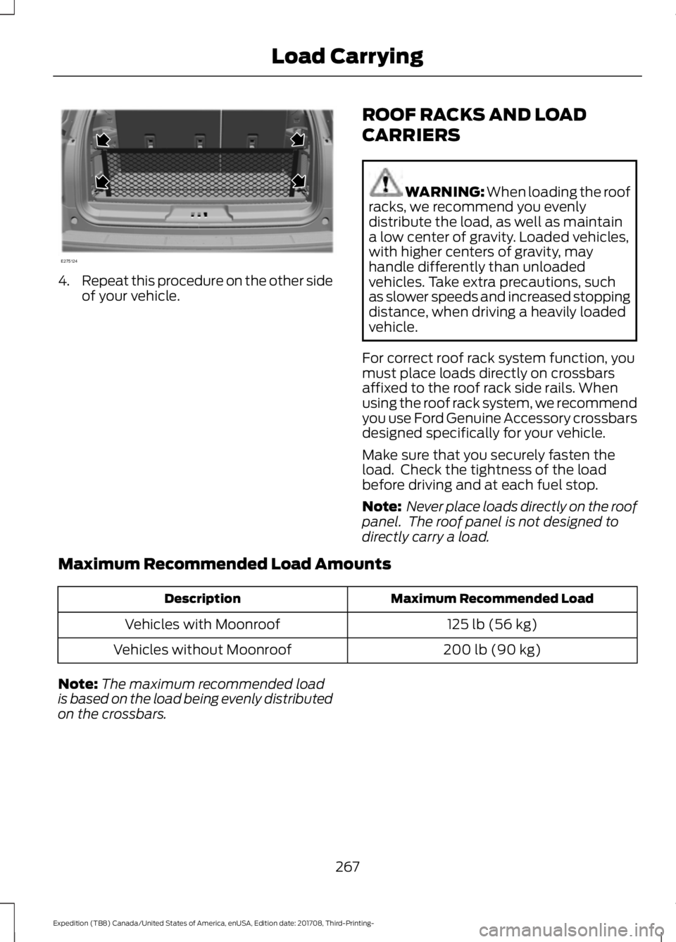
4.
Repeat this procedure on the other side
of your vehicle. ROOF RACKS AND LOAD
CARRIERS WARNING: When loading the roof
racks, we recommend you evenly
distribute the load, as well as maintain
a low center of gravity. Loaded vehicles,
with higher centers of gravity, may
handle differently than unloaded
vehicles. Take extra precautions, such
as slower speeds and increased stopping
distance, when driving a heavily loaded
vehicle.
For correct roof rack system function, you
must place loads directly on crossbars
affixed to the roof rack side rails. When
using the roof rack system, we recommend
you use Ford Genuine Accessory crossbars
designed specifically for your vehicle.
Make sure that you securely fasten the
load. Check the tightness of the load
before driving and at each fuel stop.
Note: Never place loads directly on the roof
panel. The roof panel is not designed to
directly carry a load.
Maximum Recommended Load Amounts Maximum Recommended Load
Description
125 lb (56 kg)
Vehicles with Moonroof
200 lb (90 kg)
Vehicles without Moonroof
Note: The maximum recommended load
is based on the load being evenly distributed
on the crossbars.
267
Expedition (TB8) Canada/United States of America, enUSA, Edition date: 201708, Third-Printing- Load CarryingE275124
Page 275 of 571

Helpful examples for calculating
the available amount of cargo
and luggage load capacity
Suppose your vehicle has a
1400-pound (635-kilogram) cargo
and luggage capacity. You decide
to go golfing. Is there enough load
capacity to carry you, four of your
friends and all the golf bags? You
and four friends average 220
pounds (99 kilograms) each and
the golf bags weigh approximately
30 pounds (13.5 kilograms) each.
The calculation would be: 1400 -
(5 x 220) - (5 x 30) = 1400 - 1100
- 150 = 150 pounds. Yes, you have
enough load capacity in your
vehicle to transport four friends
and your golf bags. In metric units,
the calculation would be: 635
kilograms - (5 x 99 kilograms) -
(5 x 13.5 kilograms) = 635 - 495 -
67.5 = 72.5 kilograms.
Suppose your vehicle has a
1400-pound (635-kilogram) cargo
and luggage capacity. You and
one of your friends decide to pick
up cement from the local home
improvement store to finish that
patio you have been planning for
the past two years. Measuring the
inside of the vehicle with the rear
seat folded down, you have room
for twelve 100-pound
(45-kilogram) bags of cement. Do
you have enough load capacity to
transport the cement to your
home? If you and your friend each
weigh 220 pounds (99 kilograms),
the calculation would be: 1400 -
(2 x 220) - (12 x 100) = 1400 - 440
- 1200 = - 240 pounds. No, you do
not have enough cargo capacity
to carry that much weight. In
metric units, the calculation would
be: 635 kilograms - (2 x 99
kilograms) - (12 x 45 kilograms) =
635 - 198 - 540 = -103 kilograms.
You will need to reduce the load
weight by at least 240 pounds
(104 kilograms). If you remove
three 100-pound (45-kilogram)
cement bags, then the load
calculation would be:1400 - (2 x
220) - (9 x 100) = 1400 - 440 -
900 = 60 pounds. Now you have
the load capacity to transport the
cement and your friend home. In
metric units, the calculation would
be: 635 kilograms - (2 x 99
kilograms) - (9 x 45 kilograms) =
635 - 198 - 405 = 32 kilograms.
The above calculations also
assume that the loads are
positioned in your vehicle in a
manner that does not overload
the front or the rear gross axle
weight rating specified for your
vehicle on the Safety Compliance
Certification label.
Special Loading Instructions
for Owners of Pick-up Trucks
and Utility-type Vehicles
WARNING: When loading
the roof racks, we recommend
you evenly distribute the load,
as well as maintain a low center
of gravity. Loaded vehicles, with
higher centers of gravity, may
272
Expedition (TB8) Canada/United States of America, enUSA, Edition date: 201708, Third-Printing- Load Carrying
Page 294 of 571

lever without a trailer connected. After
disconnecting the trailer connector,
press the brake pedal for
approximately five seconds to allow
the system to detect and update the
trailer status.
B: Manual control lever: Slide the control
lever to the left to turn on the trailer's
electric brakes independent of the tow
vehicle's. If you use the manual control
when the brake is also applied, the greater
of the two inputs determines the power
sent to the trailer brakes.
• Stop lamps: Using the manual control
lever illuminates both the trailer brake
lamps and your vehicle brake lamps
except the center high-mount stop
lamp, if you make the proper electrical
connection to the trailer. Pressing your
vehicle brake pedal also illuminates
both trailer and vehicle brake lamps.
Procedure for Adjusting Gain
Note: Only perform this procedure in a
traffic-free environment at speeds of
approximately
20– 25 mph (30–40 km/h).
The gain setting sets the trailer brake
controller for the specific towing condition.
You should change the setting as towing
conditions change. Changes to towing
conditions include trailer load, vehicle load,
road conditions and weather.
The gain should be set to provide the
maximum trailer braking assistance when
making sure the trailer wheels do not lock
when using the brakes. Locked trailer
wheels may lead to trailer instability.
1. Make sure the trailer brakes are in good
working condition, functioning normally
and properly adjusted. See your trailer
dealer if necessary.
2. Hook up the trailer and make the electrical connections according to the
trailer manufacturer's instructions. 3. When you plug in a trailer with electric
or electric-over-hydraulic brakes, a
message confirming connection
appears in the information display.
4. Use the gain adjustment (+ and -) buttons to increase or decrease the
gain setting to the desired starting
point. A gain setting of 6.0 is a good
starting point for heavier loads.
5. In a traffic-free environment, tow the trailer on a dry, level surface at a speed
of
20– 25 mph (30–40 km/h) and
squeeze the manual control lever
completely.
6. If the trailer wheels lock up, indicated by squealing tires, reduce the gain
setting. If the trailer wheels turn freely,
increase the gain setting. Repeat steps
5 and 6 until the gain setting is at a
point just below trailer wheel lock-up.
If towing a heavier trailer, trailer wheel
lock-up may not be attainable even
with the maximum gain setting of 10.
Explanation of Information Display
Warning Messages
Note: An authorized dealer can diagnose
the trailer brake controller to determine
exactly which trailer fault has occurred.
However, your Ford warranty does not cover
this diagnosis if the fault is with the trailer.
A message indicating a trailer brake
module fault may display in response to
faults sensed by the trailer brake controller,
accompanied by a single tone. If this
message appears, contact an authorized
dealer as soon as possible for diagnosis
and repair. The controller may still
function, but performance may be
degraded.
A message indicating a trailer wiring fault
may display when there is a short circuit
on the electric brake output wire. If this
message displays, accompanied by a
single tone, with no trailer connected, the
problem is with your vehicle wiring
291
Expedition (TB8) Canada/United States of America, enUSA, Edition date: 201708, Third-Printing- Towing
Page 366 of 571
![FORD EXPEDITION 2018 Owners Manual Note:
If you are checking tire
pressure when the tire is hot, (for
example, driven more than 1 mile
[1.6 kilometers]), never bleed or
reduce air pressure. The tires are
hot from driving and it is norm FORD EXPEDITION 2018 Owners Manual Note:
If you are checking tire
pressure when the tire is hot, (for
example, driven more than 1 mile
[1.6 kilometers]), never bleed or
reduce air pressure. The tires are
hot from driving and it is norm](/manual-img/11/40741/w960_40741-365.png)
Note:
If you are checking tire
pressure when the tire is hot, (for
example, driven more than 1 mile
[1.6 kilometers]), never bleed or
reduce air pressure. The tires are
hot from driving and it is normal for
pressures to increase above
recommended cold pressures. A
hot tire at or below recommended
cold inflation pressure could be
significantly under-inflated.
Note: If you have to drive a
distance to get air for your tire(s),
check and record the tire pressure
first and add the appropriate air
pressure when you get to the
pump. It is normal for tires to heat
up and the air pressure inside to go
up as you drive.
2. Remove the cap from the valve
on one tire, then firmly press the
tire gauge onto the valve and
measure the pressure.
3. Add enough air to reach the
recommended air pressure.
Note: If you overfill the tire, release
air by pressing on the metal stem
in the center of the valve. Then
recheck the pressure with your tire
gauge.
4. Replace the valve cap.
5. Repeat this procedure for each
tire, including the spare. Note:
Some spare tires operate at
a higher inflation pressure than the
other tires. For T type mini-spare
tires, see the Dissimilar spare wheel
and tire assembly information for
a description. Store and maintain
at 60 psi (4.15 bar). For full-size
and dissimilar spare tires, see the
Dissimilar spare wheel and tire
assembly information for a
description. Store and maintain at
the higher of the front and rear
inflation pressure as shown on the
Safety Compliance Certification
Label or Tire Label.
6. Visually inspect the tires to
make sure there are no nails or
other objects embedded that
could poke a hole in the tire and
cause an air leak.
7. Check the sidewalls to make
sure there are no gouges, cuts or
bulges.
Inspecting Your Tires and
Wheel Valve Stems
Periodically inspect the tire treads
for uneven or excessive wear and
remove objects such as stones,
nails or glass that may be wedged
in the tread grooves. Check the tire
and valve stems for holes, cracks,
or cuts that may permit air
leakage and repair or replace the
tire and replace the valve stem.
Inspect the tire sidewalls for
cracking, cuts, bruises and other
signs of damage or excessive
wear. If internal damage to the tire
is suspected, have the tire
demounted and inspected in case
363
Expedition (TB8) Canada/United States of America, enUSA, Edition date: 201708, Third-Printing- Wheels and Tires