2018 FORD E-350 brake light
[x] Cancel search: brake lightPage 110 of 323
•
Passenger(s) weight.
• Payload, cargo and luggage
weight.
• Aftermarket equipment weight.
The maximum loaded trailer
weight is this value or 10,000 lb
(4,536 kg), whichever is less.
Note: The trailer tongue load is
considered part of the payload for
your vehicle. Reduce the total
payload by the final trailer tongue
weight.
Note: Consult an authorized dealer
to determine the maximum trailer
weight allowed for your vehicle if
you are not sure.
ESSENTIAL TOWING CHECKS
Follow these guidelines for safe towing:
• Do not tow a trailer until you drive your
vehicle at least
1,000 mi (1,600 km).
• Consult your local motor vehicle laws
for towing a trailer.
• See the instructions included with
towing accessories for the proper
installation and adjustment
specifications.
• Service your vehicle more frequently if
you tow a trailer. See your scheduled
maintenance information.
• If you use a rental trailer, follow the
instructions the rental agency gives
you.
See
Load limits in the Load Carrying
chapter for load specification terms found
on the tire label and Safety Compliance
label and instructions on calculating your
vehicle's load. Remember to account for the trailer
tongue weight as part of your vehicle load
when calculating the total vehicle weight.
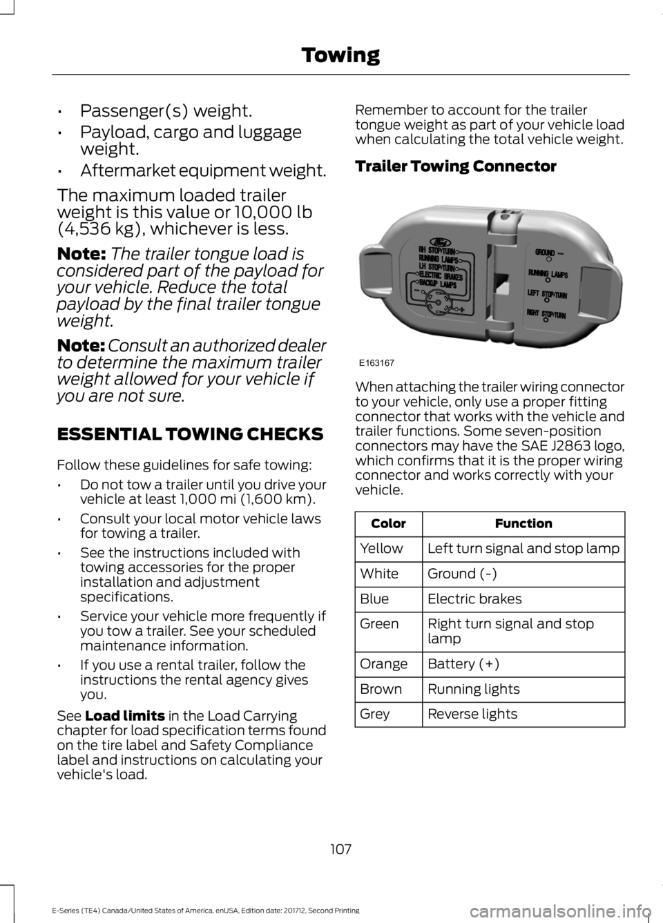
Trailer Towing Connector
When attaching the trailer wiring connector
to your vehicle, only use a proper fitting
connector that works with the vehicle and
trailer functions. Some seven-position
connectors may have the SAE J2863 logo,
which confirms that it is the proper wiring
connector and works correctly with your
vehicle.
Function
Color
Left turn signal and stop lamp
Yellow
Ground (-)
White
Electric brakes
Blue
Right turn signal and stop
lamp
Green
Battery (+)
Orange
Running lights
Brown
Reverse lights
Grey
107
E-Series (TE4) Canada/United States of America, enUSA, Edition date: 201712, Second Printing TowingE163167
Page 111 of 323
Hitches
Do not use a hitch that either clamps onto
the bumper or attaches to the axle. You
must distribute the load in your trailer so
that 10-15% of the total weight of the
trailer is on the tongue.
Weight-distributing Hitches
WARNING
Do not adjust a weight-distributing
hitch to any position where the rear
bumper of the vehicle is higher than
it was before attaching the trailer. Doing
so will defeat the function of the
weight-distributing hitch, which may cause
unpredictable handling, and could result
in serious personal injury. When hooking-up a trailer using a
weight-distributing hitch, always use the
following procedure:
1. Park the loaded vehicle, without the
trailer, on a level surface.
2. Measure the height to the top of your vehicle's front wheel opening on the
fender. This is H1.
3. Attach the loaded trailer to your vehicle
without the weight-distributing bars
connected.
4. Measure the height to the top of your vehicle's front wheel opening on the
fender a second time. This is H2.
5. Install and adjust the tension in the weight-distributing bars so that the
height of your vehicle's front wheel
opening on the fender is approximately
half the way down from H2, toward H1.
6. Check that the trailer is level or slightly
nose down toward your vehicle. If not,
adjust the ball height accordingly and
repeat Steps 2-6. When the trailer is level or slightly nose
down toward the vehicle:
•
Lock the bar tension adjuster in place.
• Check that the trailer tongue securely
attaches and locks onto the hitch.
• Install safety chains, lighting, and trailer
brake controls as required by law or the
trailer manufacturer.
Safety Chains
Note: Do not attach safety chains to the
bumper.
Always connect the safety chains to the
frame or hook retainers of your vehicle
hitch.
To connect the safety chains, cross the
chains under the trailer tongue and allow
enough slack for turning tight corners. Do
not allow the chains to drag on the ground.
Trailer Brakes WARNING
Do not connect a trailer's hydraulic
brake system directly to your
vehicle's brake system. Your vehicle
may not have enough braking power and
your chances of having a collision greatly
increase. Electric brakes and manual, automatic or
surge-type trailer brakes are safe if you
install them properly and adjust them to
the manufacturer's specifications. The
trailer brakes must meet local and federal
regulations.
The rating for the tow vehicle's braking
system operation is at the gross vehicle
weight rating, not the gross combined
weight rating.
108
E-Series (TE4) Canada/United States of America, enUSA, Edition date: 201712, Second Printing Towing
Page 114 of 323
wiring. Consult your trailer dealer for
assistance. This can be a short to ground
(such as a chaffed wire), short to voltage
(such as a pulled pin on trailer emergency
breakaway battery) or the trailer brakes
may be drawing too much current.
Points to Remember
Note:
Do not attempt removal of the trailer
brake controller without consulting the
Workshop Manual. Damage to the unit may
result.
• Adjust gain setting before using the
trailer brake controller for the first time.
• Adjust gain setting, using the procedure
above, whenever road, weather and
trailer or vehicle loading conditions
change from when the gain was initially
set.
• Only use the manual control lever for
proper adjustment of the gain during
trailer setup. Misuse, such as
application during trailer sway, could
cause instability of trailer or tow
vehicle.
• Avoid towing in adverse weather
conditions. The trailer brake controller
does not provide anti-lock control of
the trailer wheels. Trailer wheels can
lock up on slippery surfaces, resulting
in reduced stability of trailer and tow
vehicle.
• The trailer brake controller is equipped
with a feature that reduces output at
vehicle speeds below 11 mph (18 km/h)
so trailer and vehicle braking is not jerky
or harsh. This feature is only available
when applying the brakes using your
vehicle's brake pedal, not the
controller.
• The controller interacts with the brake
control system and powertrain control
system of your vehicle to provide the
best performance on different road
conditions. •
Your vehicle's brake system and the
trailer brake system work
independently of each other. Changing
the gain setting on the controller does
not affect the operation of your
vehicle's brakes whether you attach a
trailer or not.
• When you switch the engine off, the
controller output is disabled and the
display and module shut down. The
controller module and display turn on
when you switch the ignition on.
• The trailer brake controller is only a
factory-installed or dealer-installed
item. Ford is not responsible for
warranty or performance of the
controller due to misuse or customer
installation.
Trailer Lamps WARNING
Never connect any trailer lamp wiring
to the vehicle's tail lamp wiring; this
may damage the electrical system
resulting in fire. Contact your authorized
dealer as soon as possible for assistance
in proper trailer tow wiring installation.
Additional electrical equipment may be
required. Trailer lamps are required on most towed
vehicles. Make sure all running lights, brake
lights, direction indicators and hazard lights
are working.
Before Towing a Trailer
Practice turning, stopping and backing up
to get the feel of your vehicle-trailer
combination before starting on a trip.
When turning, make wider turns so the
trailer wheels clear curbs and other
obstacles.
111
E-Series (TE4) Canada/United States of America, enUSA, Edition date: 201712, Second Printing Towing
Page 118 of 323

•
Reduce the use of air conditioning and
heat.
• Avoid using speed control in hilly
terrain.
• Do not rest your foot on the brake
pedal while driving.
• Avoid carrying unnecessary weight.
• Avoid adding particular accessories to
your vehicle (e.g. bug deflectors,
rollbars/light bars, running boards, ski
racks).
• Avoid driving with the wheels out of
alignment.
DRIVING THROUGH WATER WARNING
Do not drive through flowing or deep
water as you may lose control of your
vehicle.
Note:
Driving through standing water can
cause vehicle damage.
Note: Engine damage can occur if water
enters the air filter.
Before driving through standing water,
check the depth. Never drive through water
that is higher than the bottom of the wheel
hubs. When driving through standing water, drive
very slowly and do not stop your vehicle.
Your brake performance and traction may
be limited. After driving through water and
as soon as it is safe to do so:
•
Lightly press the brake pedal to dry the
brakes and to check that they work.
• Check that the horn works.
• Check that the exterior lights work.
• Turn the steering wheel to check that
the steering power assist works.
FLOOR MATS WARNINGS
Use a floor mat designed to fit the
footwell of your vehicle that does not
obstruct the pedal area. Failure to
follow this instruction could result in the
loss of control of your vehicle, personal
injury or death. Pedals that cannot move freely can
cause loss of vehicle control and
increase the risk of serious personal
injury. Secure the floor mat to both
retention devices so that it cannot
slip out of position and interfere with
the pedals. Failure to follow this instruction
could result in the loss of control of your
vehicle, personal injury or death. Do not place additional floor mats
or any other covering on top of the
original floor mats. This could result
in the floor mat interfering with the
operation of the pedals. Failure to follow
this instruction could result in the loss of
control of your vehicle, personal injury or
death. Always make sure that objects
cannot fall into the driver foot well
while your vehicle is moving. Objects
that are loose can become trapped under
the pedals causing a loss of vehicle control. 115
E-Series (TE4) Canada/United States of America, enUSA, Edition date: 201712, Second Printing Driving HintsE176913
Page 139 of 323

Protected Components
Fuse Rating
Fuse or Relay
Number
Headlamp high beams.
15A
23
Horn (except stripped chassis).
20A
24
Demand lighting.
10A
25
Cluster (except stripped chassis).
10A
26
Ignition switch feed.
20A
27
Audio mute (start).
5A
28
Cluster (except stripped chassis).
5A
29
Not used (spare).
5A
30
Not used (spare).
10A
31
Restraints module.
10A
32
Trailer brake controller.
10A
33
Not used (spare).
5A
34
Cutaway run/start.
10A
35
Passive anti-theft system radio frequency
module.
5A
36
Climate control.
10A
37
Stripped chassis #1 run/start.
Not used (spare).
20A
38
Radio.
20A
39
Not used (spare).
20A
40
Radio.
15A
41
Switch illumination.
Automatic dimming rear view mirror.
Power inverter.
Auxiliary switch.
10A
42
Stripped chassis instrument panel
connector #1.
10A
43
Trailer tow battery charge relay.
10A
44
Wipers.
5A
45
136
E-Series (TE4) Canada/United States of America, enUSA, Edition date: 201712, Second Printing Fuses
Page 145 of 323

Only use oils certified for gasoline engines
by the American Petroleum Institute (API).
An oil with this trademark symbol
conforms to the current engine and
emission system protection standards and
fuel economy requirements of the
International Lubricants Specification
Advisory Committee (ILSAC).
To top up the engine oil level do the
following:
1. Clean the area surrounding the engine
oil filler cap before you remove it.
2. Remove the engine oil filler cap. See Under Hood Overview (page 139).
Turn it counterclockwise and remove
it.
3. Add engine oil that meets Ford specifications. See
Capacities and
Specifications (page 199). You may
have to use a funnel to pour the engine
oil into the opening.
4. Recheck the oil level.
5. If the oil level is correct, replace the dipstick and make sure it is fully seated.
6. Replace the engine oil filler cap. Turn it clockwise until you feel a strong
resistance.
Note: Do not add oil further than the
maximum mark. Oil levels above the
maximum mark may cause engine damage.
Note: Make sure you install the oil filler cap
correctly.
Note: Soak up any spillage with an
absorbent cloth immediately.
OIL CHANGE INDICATOR
RESET
(If Equipped)
Resetting the Oil Life Monitoring
System
Only reset the oil life monitoring system
after changing the engine oil and oil filter. To reset the oil life monitoring system do
the following:
1.
Switch the ignition on. Do not start the
engine.
2. Fully press the accelerator and brake pedals at the same time.
3. Keep the accelerator and brake pedals
fully pressed.
4. After three seconds, a message displays confirming the reset procedure
is in progress.
5. After 25 seconds, a message displays confirming the reset procedure is
complete.
6. Release the accelerator and brake pedals.
7. Switch the ignition off.
ENGINE COOLANT CHECK WARNINGS
Never remove the coolant reservoir
cap when the engine is running or
hot.
Do not put coolant in the windshield
washer reservoir. If sprayed on the
windshield, coolant could make it
difficult to see through the windshield. To reduce the risk of personal injury,
make sure the engine is cool before
unscrewing the coolant pressure
relief cap. The cooling system is under
pressure. Steam and hot liquid can come
out forcefully when you loosen the cap
slightly. Do not add coolant further than the
MAX mark.
When the engine is cold, check the
concentration and level of the coolant at
the intervals listed in the scheduled
maintenance information. See Scheduled
Maintenance
(page 270).
142
E-Series (TE4) Canada/United States of America, enUSA, Edition date: 201712, Second Printing Maintenance
Page 159 of 323
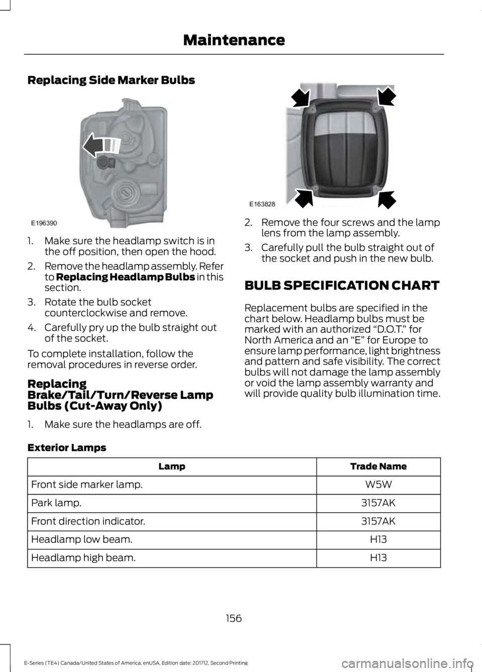
Replacing Side Marker Bulbs
1. Make sure the headlamp switch is in
the off position, then open the hood.
2. Remove the headlamp assembly. Refer
to Replacing Headlamp Bulbs in this
section.
3. Rotate the bulb socket counterclockwise and remove.
4. Carefully pry up the bulb straight out of the socket.
To complete installation, follow the
removal procedures in reverse order.
Replacing
Brake/Tail/Turn/Reverse Lamp
Bulbs (Cut-Away Only)
1. Make sure the headlamps are off. 2. Remove the four screws and the lamp
lens from the lamp assembly.
3. Carefully pull the bulb straight out of the socket and push in the new bulb.
BULB SPECIFICATION CHART
Replacement bulbs are specified in the
chart below. Headlamp bulbs must be
marked with an authorized “D.O.T.” for
North America and an “E” for Europe to
ensure lamp performance, light brightness
and pattern and safe visibility. The correct
bulbs will not damage the lamp assembly
or void the lamp assembly warranty and
will provide quality bulb illumination time.
Exterior Lamps Trade Name
Lamp
W5W
Front side marker lamp.
3157AK
Park lamp.
3157AK
Front direction indicator.
H13
Headlamp low beam.
H13
Headlamp high beam.
156
E-Series (TE4) Canada/United States of America, enUSA, Edition date: 201712, Second Printing MaintenanceE196390 E163828
Page 160 of 323
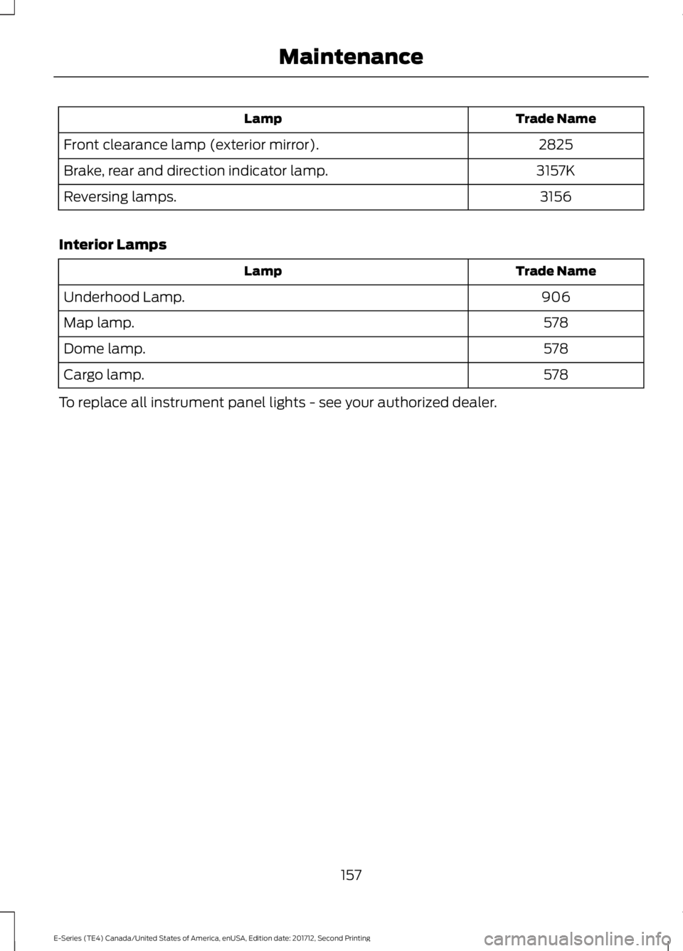
Trade Name
Lamp
2825
Front clearance lamp (exterior mirror).
3157K
Brake, rear and direction indicator lamp.
3156
Reversing lamps.
Interior Lamps Trade Name
Lamp
906
Underhood Lamp.
578
Map lamp.
578
Dome lamp.
578
Cargo lamp.
To replace all instrument panel lights - see your authorized dealer.
157
E-Series (TE4) Canada/United States of America, enUSA, Edition date: 201712, Second Printing Maintenance