2018 DODGE CHARGER USB port
[x] Cancel search: USB portPage 116 of 553
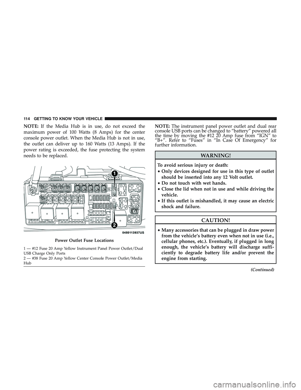
NOTE:If the Media Hub is in use, do not exceed the
maximum power of 100 Watts (8 Amps) for the center
console power outlet. When the Media Hub is not in use,
the outlet can deliver up to 160 Watts (13 Amps). If the
power rating is exceeded, the fuse protecting the system
needs to be replaced. NOTE:
The instrument panel power outlet and dual rear
console USB ports can be changed to “battery” powered all
the time by moving the #12 20 Amp fuse from “IGN” to
“B+”. Refer to “Fuses” in “In Case Of Emergency” for
further information.
WARNING!
To avoid serious injury or death:
• Only devices designed for use in this type of outlet
should be inserted into any 12 Volt outlet.
• Do not touch with wet hands.
• Close the lid when not in use and while driving the
vehicle.
• If this outlet is mishandled, it may cause an electric
shock and failure.
CAUTION!
•Many accessories that can be plugged in draw power
from the vehicle’s battery even when not in use (i.e.,
cellular phones, etc.). Eventually, if plugged in long
enough, the vehicle’s battery will discharge suffi-
ciently to degrade battery life and/or prevent the
engine from starting.
(Continued)
Power Outlet Fuse Locations
1 — #12 Fuse 20 Amp Yellow Instrument Panel Power Outlet/Dual
USB Charge Only Ports
2 — #38 Fuse 20 Amp Yellow Center Console Power Outlet/Media
Hub 114 GETTING TO KNOW YOUR VEHICLE
Page 132 of 553
The electrical loads that may be switched off (if equipped),
and vehicle functions which can be affected by load
reduction:
•Heated Seat/Vented Seats/Heated Wheel
• Heated/Cooled Cup Holders — If Equipped
• Rear Defroster And Heated Mirrors
• HVAC System
• 115V AC Power Inverter System
• Audio and Telematics System
Loss of the battery charge may indicate one or more of the
following conditions:
• The charging system cannot deliver enough electrical
power to the vehicle system because the electrical loads
are larger than the capability of charging system. The
charging system is still functioning properly.
• Turning on all possible vehicle electrical loads (e.g.
HVAC to max settings, exterior and interior lights,
overloaded power outlets +12V, 115V AC, USB ports)
during certain driving conditions (city driving, towing,
frequent stopping). •
Installing options like additional lights, upfitter electri-
cal accessories, audio systems, alarms and similar de-
vices.
• Unusual driving cycles (short trips separated by long
parking periods).
• The vehicle was parked for an extended period of time
(weeks, months).
• The battery was recently replaced and was not charged
completely.
• The battery was discharged by an electrical load left on
when the vehicle was parked.
• The battery was used for an extended period with the
engine not running to supply radio, lights, chargers,
+12V portable appliances like vacuum cleaners, game
consoles and similar devices.
130 GETTING TO KNOW YOUR INSTRUMENT PANEL
Page 133 of 553

What to do when an electrical load reduction action
message is present (“Battery Saver On” or “Battery Saver
Mode”)
During a trip:
•Reduce power to unnecessary loads if possible:
– Turn off redundant lights (interior or exterior)
– Check what may be plugged in to power outlets +12V, 115V AC, USB ports
– Check HVAC settings (blower, temperature)
– Check the audio settings (volume)
After a trip:
• Check if any aftermarket equipment was installed (ad-
ditional lights, upfitter electrical accessories, audio sys-
tems, alarms) and review specifications if any (load and
Ignition Off Draw currents).
• Evaluate the latest driving cycles (distance, driving time
and parking time).
• The vehicle should have service performed if the mes-
sage is still present during consecutive trips and the
evaluation of the vehicle and driving pattern did not
help to identify the cause.WARNING LIGHTS AND MESSAGES
The warning/indicator lights will illuminate in the instru-
ment panel together with a dedicated message and/or
acoustic signal when applicable. These indications are
indicative and precautionary and as such must not be
considered as exhaustive and/or alternative to the infor-
mation contained in the Owner ’s Manual, which you are
advised to read carefully in all cases. Always refer to the
information in this chapter in the event of a failure indica-
tion. All active telltales will display first if applicable. The
system check menu may appear different based upon
equipment options and current vehicle status. Some tell-
tales are optional and may not appear.
Red Warning Lights
— Air Bag Warning Light
This warning light will illuminate to indicate a fault with
the air bag, and will turn on for four to eight seconds as a
bulb check when the ignition is placed in the ON/RUN or
ACC/ON/RUN position. This light will illuminate with a
single chime when a fault with the air bag has been
detected, it will stay on until the fault is cleared. If the light
is either not on during startup, stays on, or turns on while
driving, have the system inspected at an authorized dealer
as soon as possible.
4
GETTING TO KNOW YOUR INSTRUMENT PANEL 131
Page 321 of 553
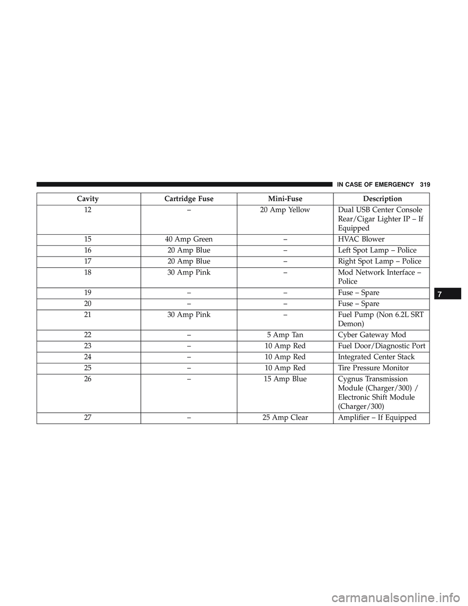
CavityCartridge Fuse Mini-FuseDescription
12 –20 Amp Yellow Dual USB Center Console
Rear/Cigar Lighter IP – If
Equipped
15 40 Amp Green –HVAC Blower
16 20 Amp Blue –Left Spot Lamp – Police
17 20 Amp Blue –Right Spot Lamp – Police
18 30 Amp Pink –Mod Network Interface –
Police
19 ––Fuse – Spare
20 ––Fuse – Spare
21 30 Amp Pink –Fuel Pump (Non 6.2L SRT
Demon)
22 –5 Amp Tan Cyber Gateway Mod
23 –10 Amp Red Fuel Door/Diagnostic Port
24 –10 Amp Red Integrated Center Stack
25 –10 Amp Red Tire Pressure Monitor
26 –15 Amp Blue Cygnus Transmission
Module (Charger/300) /
Electronic Shift Module
(Charger/300)
27 –25 Amp Clear Amplifier – If Equipped
7
IN CASE OF EMERGENCY 319
Page 441 of 553
NOTE:
•FCA US LLC or your dealer may contact you directly
regarding software updates.
• To help further improve vehicle security and minimize
the potential risk of a security breach, vehicle owners
should:
• Routinely check www.driveuconnect.com/support/
software-update.html (U.S. Residents) or www.driveu-
connect.ca (Canadian Residents) to learn about avail-
able Uconnect software updates.
• Only connect and use trusted media devices (e.g.
personal mobile phones, USBs, CDs).
Privacy of any wireless and wired communications cannot
be assured. Third parties may unlawfully intercept infor-
mation and private communications without your consent.
For further information, refer to “Data Collection & Pri-
vacy” in your Uconnect Owner ’s Manual Supplement or
“Onboard Diagnostic System (OBD II) Cybersecurity” in
“Getting To Know Your Instrument Panel”.UCONNECT SETTINGS
The Uconnect system uses a combination of buttons on the
touchscreen and buttons on the faceplate located on the
center of the instrument panel that allows you to access
and change the customer programmable features.
CAUTION!
Do NOT attach any object to the touchscreen, doing so
can result in damage to the touchscreen.
10
MULTIMEDIA 439
Page 507 of 553
The left-hand control is a rocker-type switch with a push-
button in the center. The function of the left-hand control is
different depending on which mode you are in.
The following describes the left-hand control operation in
each mode.
Radio Operation
Pushing the top of the switch will “Seek” up for the next
listenable station and pushing the bottom of the switch will
“Seek” down for the next listenable station.
The button located in the center of the left-hand control
will tune to the next preset station that you have pro-
grammed in the radio preset button.
Media Mode
Pushing the top of the switch once goes to the next track on
the selected media (AUX/USB/Bluetooth). Pushing the
bottom of the switch once goes to the beginning of the
current track, or to the beginning of the previous track if it
is within eight seconds after the current track begins to
play.
AUX/USB/MP3 CONTROL
This feature allows an external USB device to be plugged
into the USB port.
For further information, refer to the Uconnect Owner ’s
Manual Supplement.
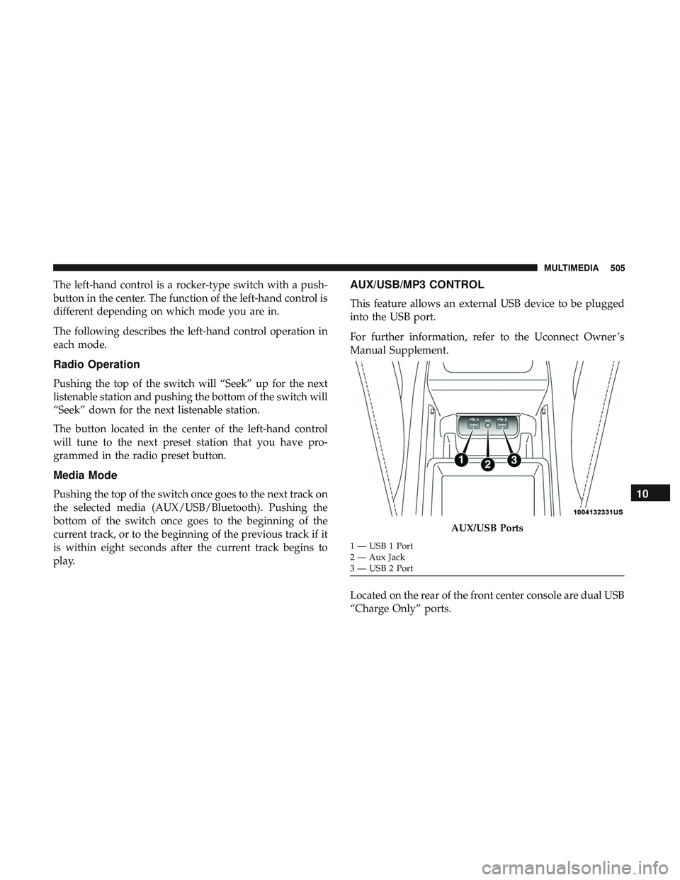
Located on the rear of the front center console are dual USB
“Charge Only” ports.
AUX/USB Ports
1 — USB 1 Port
2 — Aux Jack
3 — USB 2 Port
10
MULTIMEDIA 505
Page 508 of 553
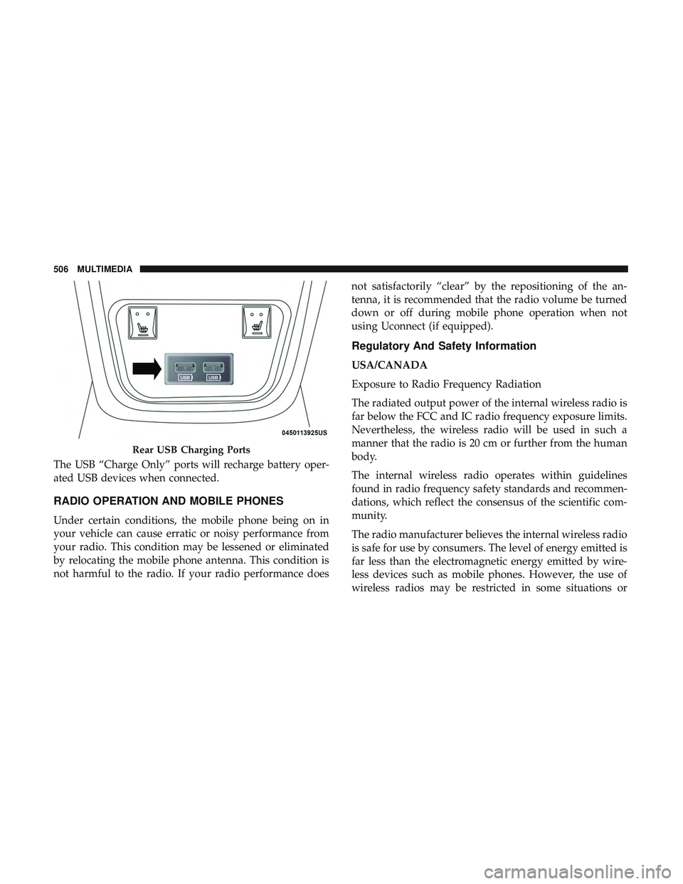
The USB “Charge Only” ports will recharge battery oper-
ated USB devices when connected.
RADIO OPERATION AND MOBILE PHONES
Under certain conditions, the mobile phone being on in
your vehicle can cause erratic or noisy performance from
your radio. This condition may be lessened or eliminated
by relocating the mobile phone antenna. This condition is
not harmful to the radio. If your radio performance doesnot satisfactorily “clear” by the repositioning of the an-
tenna, it is recommended that the radio volume be turned
down or off during mobile phone operation when not
using Uconnect (if equipped).
Regulatory And Safety Information
USA/CANADA
Exposure to Radio Frequency Radiation
The radiated output power of the internal wireless radio is
far below the FCC and IC radio frequency exposure limits.
Nevertheless, the wireless radio will be used in such a
manner that the radio is 20 cm or further from the human
body.
The internal wireless radio operates within guidelines
found in radio frequency safety standards and recommen-
dations, which reflect the consensus of the scientific com-
munity.
The radio manufacturer believes the internal wireless radio
is safe for use by consumers. The level of energy emitted is
far less than the electromagnetic energy emitted by wire-
less devices such as mobile phones. However, the use of
wireless radios may be restricted in some situations or
Rear USB Charging Ports
506 MULTIMEDIA
Page 514 of 553
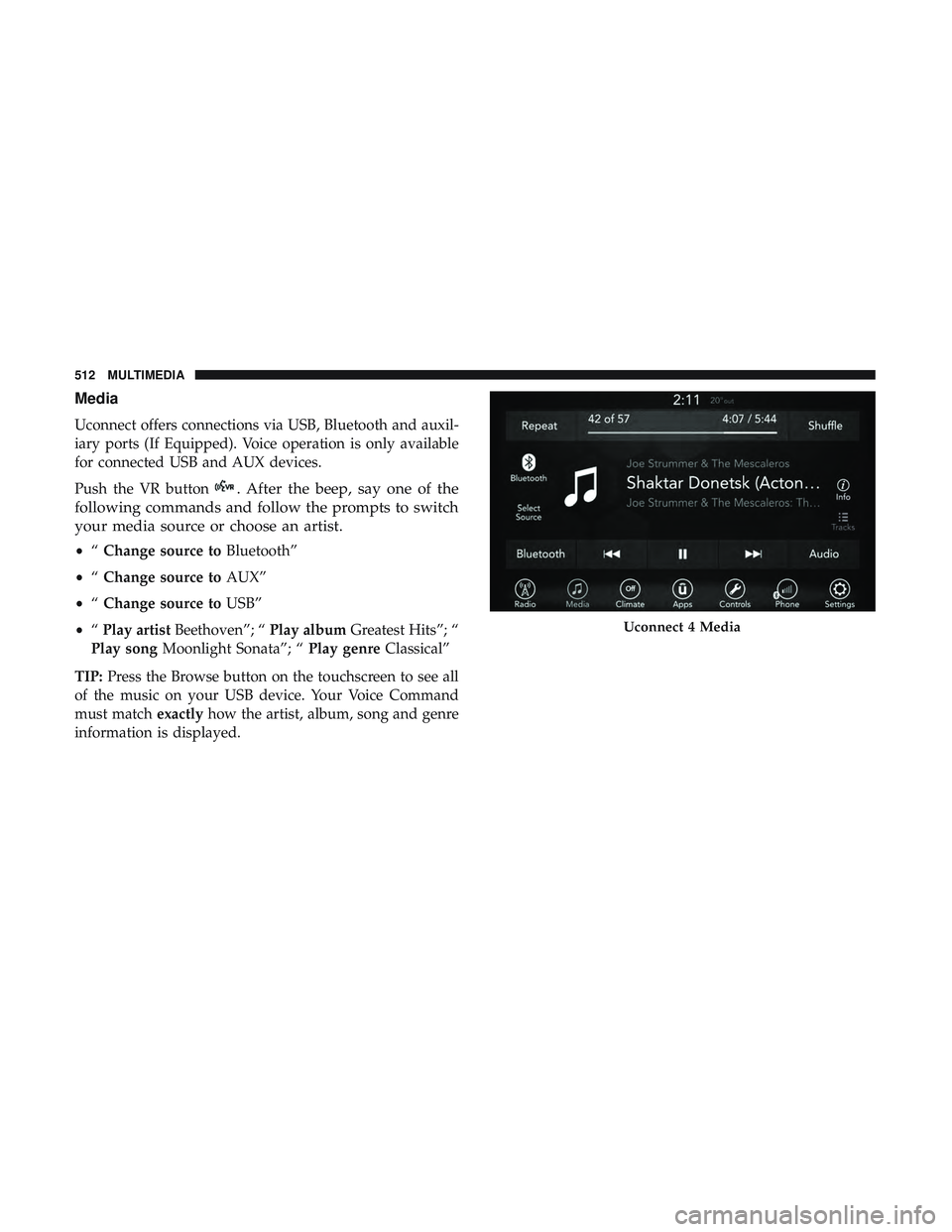
Media
Uconnect offers connections via USB, Bluetooth and auxil-
iary ports (If Equipped). Voice operation is only available
for connected USB and AUX devices.
Push the VR button
. After the beep, say one of the
following commands and follow the prompts to switch
your media source or choose an artist.
• “Change source to Bluetooth”
• “Change source to AUX”
• “Change source to USB”
• “Play artist Beethoven”; “ Play albumGreatest Hits”; “
Play song Moonlight Sonata”; “ Play genreClassical”
TIP: Press the Browse button on the touchscreen to see all
of the music on your USB device. Your Voice Command
must match exactlyhow the artist, album, song and genre
information is displayed.
Uconnect 4 Media
512 MULTIMEDIA