Page 62 of 553

The heated steering wheel control button is located within
the Uconnect system. You can gain access to the control
button through the climate screen or the controls screen.
•Press the heated steering wheel button
once to turn
the heating element on.
• Press the heated steering wheel buttona second time
to turn the heating element off.
NOTE: The engine must be running for the heated steering
wheel to operate.
Vehicles Equipped With Remote Start
On models that are equipped with remote start, the heated
steering wheel can be programmed to come on during a
remote start through the Uconnect system. Refer to
“Uconnect Settings” in “Multimedia” for further informa-
tion.
WARNING!
• Persons who are unable to feel pain to the skin
because of advanced age, chronic illness, diabetes,
spinal cord injury, medication, alcohol use, exhaus-
tion, or other physical conditions must exercise care
when using the steering wheel heater. It may cause
burns even at low temperatures, especially if used
for long periods.
• Do not place anything on the steering wheel that
insulates against heat, such as a blanket or steering
wheel covers of any type and material. This may
cause the steering wheel heater to overheat.
MIRRORS
Inside Day/Night Mirror — If Equipped
A single ball joint mirror is provided in the vehicle. It is a
twist on mirror that has a fixed position at the windshield.
The mirror installs on the windshield button with a coun-
terclockwise rotation and requires no tools for mounting.
The mirror head can be adjusted up, down, left, and right
for various drivers. The mirror should be adjusted to center
on the view through the rear window.
60 GETTING TO KNOW YOUR VEHICLE
Page 67 of 553
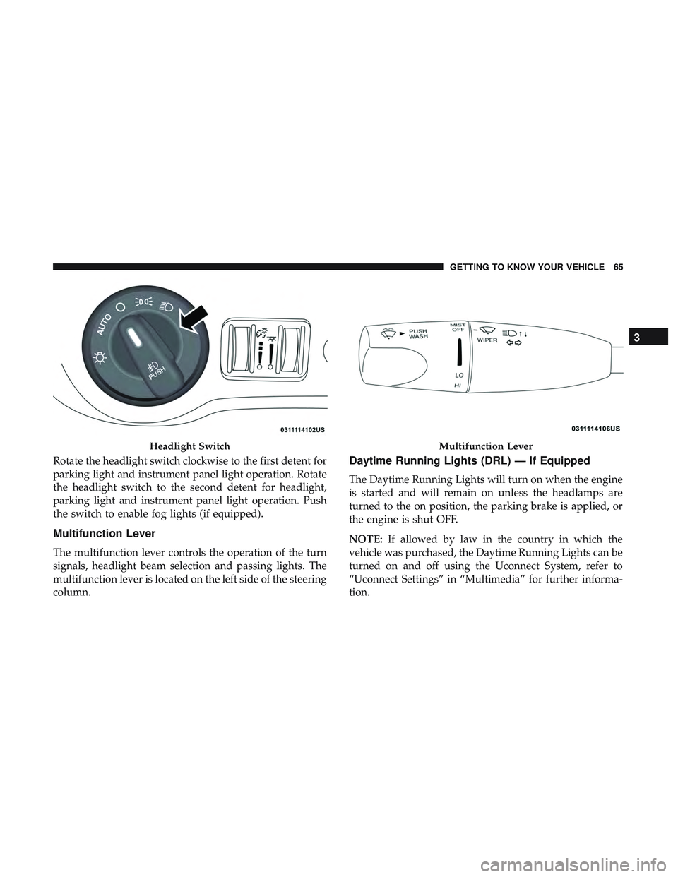
Rotate the headlight switch clockwise to the first detent for
parking light and instrument panel light operation. Rotate
the headlight switch to the second detent for headlight,
parking light and instrument panel light operation. Push
the switch to enable fog lights (if equipped).
Multifunction Lever
The multifunction lever controls the operation of the turn
signals, headlight beam selection and passing lights. The
multifunction lever is located on the left side of the steering
column.
Daytime Running Lights (DRL) — If Equipped
The Daytime Running Lights will turn on when the engine
is started and will remain on unless the headlamps are
turned to the on position, the parking brake is applied, or
the engine is shut OFF.
NOTE:If allowed by law in the country in which the
vehicle was purchased, the Daytime Running Lights can be
turned on and off using the Uconnect System, refer to
“Uconnect Settings” in “Multimedia” for further informa-
tion.
Headlight SwitchMultifunction Lever
3
GETTING TO KNOW YOUR VEHICLE 65
Page 69 of 553
To Deactivate
1. Pull the multifunction lever toward you (or rearward invehicle) to manually deactivate the system (normal
operation of low beams).
2. Push back on the multifunction lever to reactivate the system.
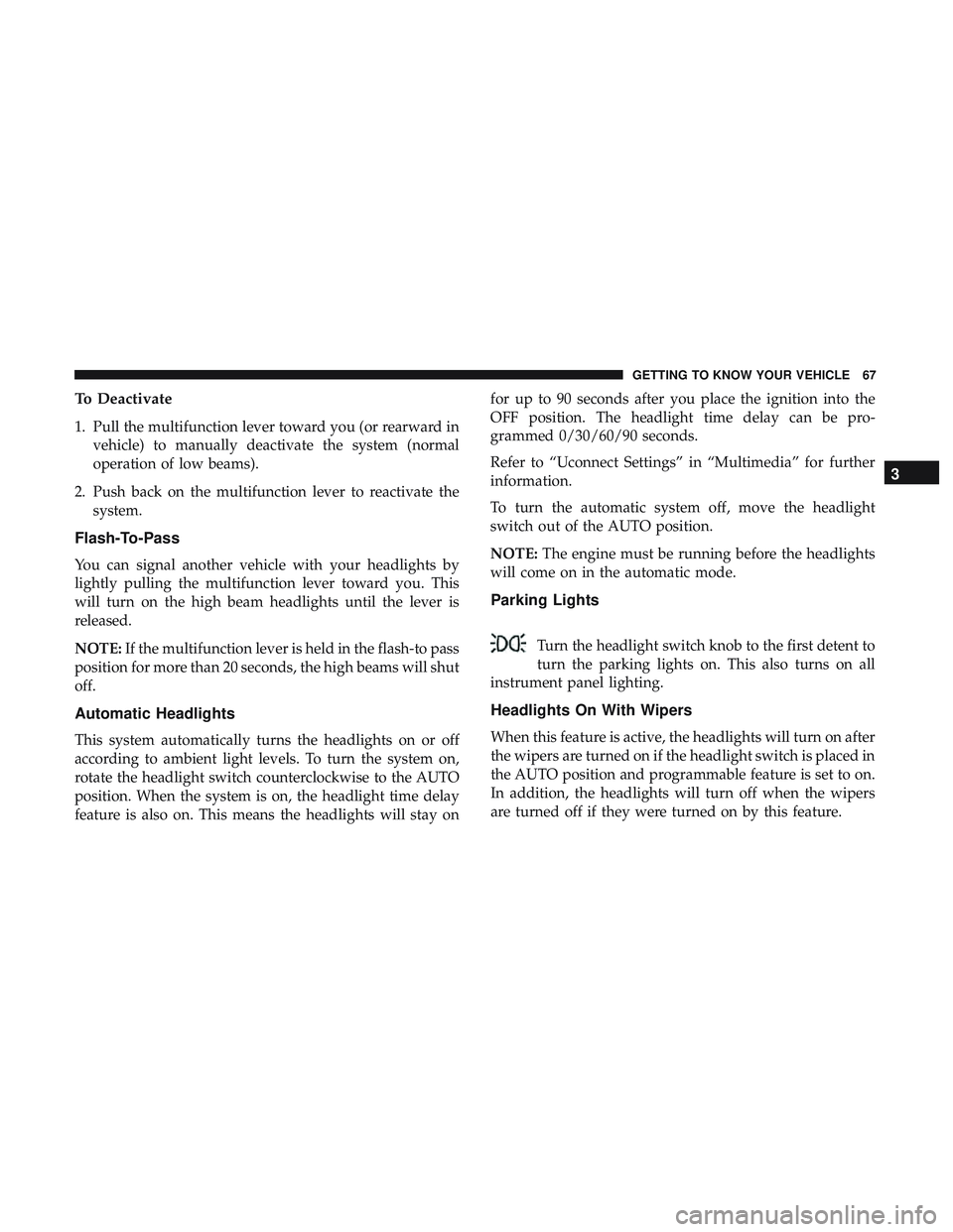
Flash-To-Pass
You can signal another vehicle with your headlights by
lightly pulling the multifunction lever toward you. This
will turn on the high beam headlights until the lever is
released.
NOTE: If the multifunction lever is held in the flash-to pass
position for more than 20 seconds, the high beams will shut
off.
Automatic Headlights
This system automatically turns the headlights on or off
according to ambient light levels. To turn the system on,
rotate the headlight switch counterclockwise to the AUTO
position. When the system is on, the headlight time delay
feature is also on. This means the headlights will stay on for up to 90 seconds after you place the ignition into the
OFF position. The headlight time delay can be pro-
grammed 0/30/60/90 seconds.
Refer to “Uconnect Settings” in “Multimedia” for further
information.
To turn the automatic system off, move the headlight
switch out of the AUTO position.
NOTE:
The engine must be running before the headlights
will come on in the automatic mode.
Parking Lights
Turn the headlight switch knob to the first detent to
turn the parking lights on. This also turns on all
instrument panel lighting.
Headlights On With Wipers
When this feature is active, the headlights will turn on after
the wipers are turned on if the headlight switch is placed in
the AUTO position and programmable feature is set to on.
In addition, the headlights will turn off when the wipers
are turned off if they were turned on by this feature.
3
GETTING TO KNOW YOUR VEHICLE 67
Page 75 of 553
Parade Mode (Daytime Brightness Feature)
Rotate the instrument panel dimmer control upward to the
first detent. This feature brightens all text displays such as
the odometer, instrument cluster display, and radio when
the position lights or headlights are on.
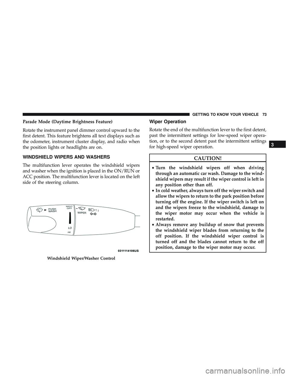
WINDSHIELD WIPERS AND WASHERS
The multifunction lever operates the windshield wipers
and washer when the ignition is placed in the ON/RUN or
ACC position. The multifunction lever is located on the left
side of the steering column.
Wiper Operation
Rotate the end of the multifunction lever to the first detent,
past the intermittent settings for low-speed wiper opera-
tion, or to the second detent past the intermittent settings
for high-speed wiper operation.
CAUTION!
•Turn the windshield wipers off when driving
through an automatic car wash. Damage to the wind-
shield wipers may result if the wiper control is left in
any position other than off.
• In cold weather, always turn off the wiper switch and
allow the wipers to return to the park position before
turning off the engine. If the wiper switch is left on
and the wipers freeze to the windshield, damage to
the wiper motor may occur when the vehicle is
restarted.
• Always remove any buildup of snow that prevents
the windshield wiper blades from returning to the
off position. If the windshield wiper control is
turned off and the blades cannot return to the off
position, damage to the wiper motor may occur.
Windshield Wiper/Washer Control
3
GETTING TO KNOW YOUR VEHICLE 73
Page 91 of 553
NOTE:
•It is not necessary to move the temperature settings for
cold or hot vehicles. The system automatically adjusts
the temperature, mode, and blower speed to provide
comfort as quickly as possible.
• The temperature can be displayed in U.S. or Metric units
by selecting the US/Metric customer-programmable fea-
ture. Refer to the “Uconnect Settings” in “Multimedia”
for further information.
To provide you with maximum comfort in the Automatic
mode during cold start-ups, the blower fan will remain on
low until the engine warms up. The blower will increase in
speed and transition into Auto mode.
Manual Operation Override
This system offers a full complement of manual override
features. The AUTO symbol in the front ATC display will
be turned off when the system is being used in the manual
mode.
Operating Tips
NOTE: Refer to the chart at the end of this section for
suggested control settings for various weather conditions.
Summer Operation
The engine cooling system must be protected with a
high-quality antifreeze coolant to provide proper corrosion
protection and to protect against engine overheating. OAT
coolant (conforming to MS.90032) is recommended.
Winter Operation
To ensure the best possible heater and defroster perfor-
mance, make sure the engine cooling system is functioning
properly and the proper amount, type, and concentration
of coolant is used. Use of the Air Recirculation mode
during Winter months is not recommended, because it may
cause window fogging.
Vacation/Storage
Before you store your vehicle, or keep it out of service (i.e.,
vacation) for two weeks or more, run the air conditioning
system at idle for about five minutes, in fresh air with the
blower setting on high. This will ensure adequate system
lubrication to minimize the possibility of compressor dam-
age when the system is started again.
3
GETTING TO KNOW YOUR VEHICLE 89
Page 116 of 553
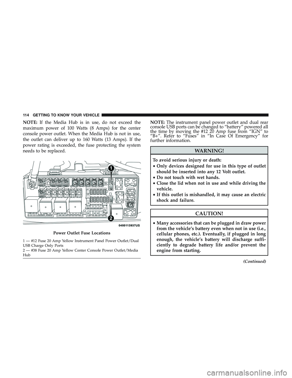
NOTE:If the Media Hub is in use, do not exceed the
maximum power of 100 Watts (8 Amps) for the center
console power outlet. When the Media Hub is not in use,
the outlet can deliver up to 160 Watts (13 Amps). If the
power rating is exceeded, the fuse protecting the system
needs to be replaced. NOTE:
The instrument panel power outlet and dual rear
console USB ports can be changed to “battery” powered all
the time by moving the #12 20 Amp fuse from “IGN” to
“B+”. Refer to “Fuses” in “In Case Of Emergency” for
further information.
WARNING!
To avoid serious injury or death:
• Only devices designed for use in this type of outlet
should be inserted into any 12 Volt outlet.
• Do not touch with wet hands.
• Close the lid when not in use and while driving the
vehicle.
• If this outlet is mishandled, it may cause an electric
shock and failure.
CAUTION!
•Many accessories that can be plugged in draw power
from the vehicle’s battery even when not in use (i.e.,
cellular phones, etc.). Eventually, if plugged in long
enough, the vehicle’s battery will discharge suffi-
ciently to degrade battery life and/or prevent the
engine from starting.
(Continued)
Power Outlet Fuse Locations
1 — #12 Fuse 20 Amp Yellow Instrument Panel Power Outlet/Dual
USB Charge Only Ports
2 — #38 Fuse 20 Amp Yellow Center Console Power Outlet/Media
Hub 114 GETTING TO KNOW YOUR VEHICLE
Page 119 of 553
GETTING TO KNOW YOUR INSTRUMENT PANEL
CONTENTS
�INSTRUMENT CLUSTER ..................118
▫ Instrument Cluster Descriptions ............121
� INSTRUMENT CLUSTER DISPLAY ...........122
▫ Location And Controls ...................122
▫ Engine Oil Life Reset ....................124
▫ Instrument Cluster Display Selectable
Menu Items ..........................125
▫ Battery Saver On/Battery Saver Mode Message —
Electrical Load Reduction Actions — If
Equipped ............................129
� WARNING LIGHTS AND MESSAGES .........131
▫ Red Warning Lights .....................131 ▫
Yellow Warning Lights ...................135
▫ Yellow Indicator Lights ...................140
▫ Green Indicator Lights ...................140
▫ White Indicator Lights ...................141
▫ Blue Indicator Lights ....................142
� ONBOARD DIAGNOSTIC SYSTEM — OBD II . . .142
▫ Onboard Diagnostic System (OBD II)
Cybersecurity ........................ .142
� EMISSIONS INSPECTION AND
MAINTENANCE PROGRAMS ..............1434
Page 120 of 553
INSTRUMENT CLUSTER
Instrument Cluster For 3.6L Engine
118 GETTING TO KNOW YOUR INSTRUMENT PANEL