2018 DODGE CHALLENGER brake light
[x] Cancel search: brake lightPage 192 of 516

WARNING!(Continued)
mat for the specific make, model, and year of your
vehicle.
• ONLY use the driver ’s side floor mat on the driver ’s
side floor area. To check for interference, with the
vehicle properly parked with the engine off, fully
depress the accelerator, the brake, and the clutch
pedal (if present) to check for interference. If your
floor mat interferes with the operation of any pedal,
or is not secure to the floor, remove the floor mat
from the vehicle and place the floor mat in your
trunk.
• ONLY use the passenger ’s side floor mat on the
passenger ’s side floor area.
• ALWAYS make sure objects cannot fall or slide into
the driver ’s side floor area when the vehicle is
moving. Objects can become trapped under accelera-
tor, brake, or clutch pedals and could cause a loss of
vehicle control.
• NEVER place any objects under the floor mat (e.g.,
towels, keys, etc.). These objects could change the
position of the floor mat and may cause interference
with the accelerator, brake, or clutch pedals.
(Continued)
WARNING! (Continued)
•If the vehicle carpet has been removed and re-
installed, always properly attach carpet to the floor
and check the floor mat fasteners are secure to the
vehicle carpet. Fully depress each pedal to check for
interference with the accelerator, brake, or clutch
pedals then re-install the floor mats.
• It is recommended to only use mild soap and water
to clean your floor mats. After cleaning, always check
your floor mat has been properly installed and is
secured to your vehicle using the floor mat fasteners
by lightly pulling mat.
Periodic Safety Checks You Should Make Outside
The Vehicle
Tires
Examine tires for excessive tread wear and uneven wear
patterns. Check for stones, nails, glass, or other objects
lodged in the tread or sidewall. Inspect the tread for cuts
and cracks. Inspect sidewalls for cuts, cracks, and bulges.
Check the wheel nuts for tightness. Check the tires (includ-
ing spare) for proper cold inflation pressure.
190 SAFETY
Page 193 of 516

Lights
Have someone observe the operation of brake lights and
exterior lights while you work the controls. Check turn
signal and high beam indicator lights on the instrument
panel.
Door Latches
Check for proper closing, latching, and locking.
Fluid Leaks
Check area under the vehicle after overnight parking for
fuel, coolant, oil, or other fluid leaks. Also, if gasoline
fumes are detected or if fuel, or brake fluid leaks are
suspected. The cause should be located and corrected
immediately.
5
SAFETY 191
Page 204 of 516

PARKING BRAKE
Before leaving the vehicle, make sure that the parking
brake is fully applied and place the gear selector in the
PARK or REVERSE (manual transmission only) position.
When the parking brake is applied and the ignition switch
is in the ON/RUN position, the “Brake Warning Light” in
the instrument cluster will illuminate.
NOTE:
•When the parking brake is applied and the transmission
is placed in gear, the “Brake Warning Light” will flash. If
vehicle speed is detected, a chime will sound to alert the
driver. Fully release the parking brake before attempting
to move the vehicle.
• This light only shows that the parking brake is applied.
It does not show the degree of brake application.
When parking on a hill, it is important to turn the front
wheels toward the curb on a downhill grade and away
from the curb on an uphill grade. For vehicles equipped
with an automatic transmission, apply the parking brake
before placing the gear selector in PARK, otherwise the
load on the transmission locking mechanism may make it difficult to move the gear selector out of PARK. The
parking brake should always be applied whenever the
driver is not in the vehicle.
Manual Transmission — If Equipped
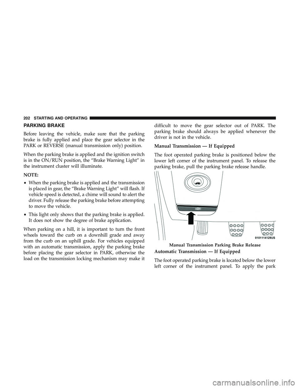
The foot operated parking brake is positioned below the
lower left corner of the instrument panel. To release the
parking brake, pull the parking brake release handle.
Automatic Transmission — If Equipped
The foot operated parking brake is located below the lower
left corner of the instrument panel. To apply the park
Manual Transmission Parking Brake Release
202 STARTING AND OPERATING
Page 206 of 516

WARNING!(Continued)
•Always fully apply the parking brake when leaving
your vehicle, or it may roll and cause damage or
injury. Also be certain to leave the transmission in
PARK. Failure to do so may allow the vehicle to roll
and cause damage or injury.
CAUTION!
If the Brake Warning Light remains on with the park-
ing brake released, a brake system malfunction is
indicated. Have the brake system serviced by an au-
thorized dealer immediately.
MANUAL TRANSMISSION — IF EQUIPPED
Six-Speed Manual Transmission
WARNING!
You or others could be injured if you leave the vehicle
unattended without having the park brake fully ap-
plied. The park brake should always be applied when
the driver is not in the vehicle, especially on an incline.
CAUTION!
• Never drive with your foot resting on the clutch
pedal, or try to hold the vehicle on a hill with the
clutch pedal partially engaged, as this will cause
abnormal wear on the clutch. Refer to “Electronic
Brake Control System/Hill Start Assist” in “Safety”
for further information.
• Failure to press the clutch pedal fully to the floor
may cause increased shift efforts, and may result in
damage to the clutch and transmission.
• Do not rest your hand on the shift lever while
driving, as this may result in transmission synchro-
nizer damage.
• Do not attempt to shift the transmission if the rear
wheels are spinning due to loss of traction. Damage
to the transmission may occur.
NOTE: During cold weather, you may experience in-
creased effort in shifting until the transmission fluid warms
up. This is normal.
204 STARTING AND OPERATING
Page 224 of 516

WARNING!
Speed Control can be dangerous where the system
cannot maintain a constant speed. Your vehicle could
go too fast for the conditions, and you could lose
control and have an accident. Do not use Speed Control
in heavy traffic or on roads that are winding, icy,
snow-covered or slippery.
To Resume Speed
To resume a previously set speed, push the RES button and
release. Resume can be used at any speed above 20 mph
(32 km/h).
To Deactivate
A soft tap on the brake pedal, pushing the CANC button,
or normal brake pressure while slowing the vehicle will
deactivate the Speed Control without erasing the set speed
from memory.
Pushing the on/off button or turning the ignition switch
OFF erases the set speed from memory.
ADAPTIVE CRUISE CONTROL (ACC) — IF
EQUIPPED
Adaptive Cruise Control (ACC) increases the driving con-
venience provided by cruise control while traveling on
highways and major roadways. However, it is not a safety
system and not designed to prevent collisions.Speed
Control function performs differently. Please refer to the
proper section within this chapter.
ACC will allow you to keep cruise control engaged in light
to moderate traffic conditions without the constant need to
reset your cruise control. ACC utilizes a radar sensor
designed to detect a vehicle directly ahead of you.
NOTE:
• If the sensor does not detect a vehicle ahead of you, ACC
will maintain a fixed set speed.
• If the ACC sensor detects a vehicle ahead, ACC will
apply limited braking or acceleration (not to exceed the
original set speed) automatically to maintain a preset
following distance, while matching the speed of the
vehicle ahead.
222 STARTING AND OPERATING
Page 231 of 516

Metric Speed (km/h)
•Pushing the SET (-)button once will result in a 1 km/h
decrease in set speed. Each subsequent tap of the button
results in a decrease of 1 km/h.
• If the button is continually pushed, the set speed will
continue to decrease in 10 km/h increments until the
button is released. The decrease in set speed is reflected
in the instrument cluster display.
NOTE:
• When you override and push the SET (+)button or SET
(-) buttons, the new Set Speed will be the current speed
of the vehicle.
• When you use the SET (-)button to decelerate, if the
engine’s braking power does not slow the vehicle suffi-
ciently to reach the set speed, the brake system will
automatically slow the vehicle.
• The ACC system applies the brake down to 15 mph
(24 km/h) when following a target vehicle.
• The ACC system maintains set speed when driving up
hill and down hill. However, a slight speed change on
moderate hills is normal. In addition, downshifting may
occur while climbing uphill or descending downhill.
This is normal operation and necessary to maintain set speed. When driving up hill and down hill, the ACC
system will cancel if the braking temperature exceeds
normal range (overheated).
Setting The Following Distance In ACC
The specified following distance for ACC can be set by
varying the distance setting between four bars (longest),
three bars (long), two bars (medium) and one bar (short).
Using this distance setting and the vehicle speed, ACC
calculates and sets the distance to the vehicle ahead. This
distance setting will show in the instrument cluster display.
Distance Setting 4 Bars (Longest)
6
STARTING AND OPERATING 229
Page 233 of 516

To increase the distance setting, push the Distance Setting —
Increase button and release. Each time the button is pushed,
the distance setting increases by one bar (longer).
To decrease the distance setting, push the Distance Setting —
Decrease button and release. Each time the button is pushed,
the distance setting decreases by one bar (shorter).
If there is no vehicle ahead, the vehicle will maintain the set
speed. If a slower moving vehicle is detected in the same
lane, the instrument cluster display will show the “SensedVehicle Indicator” icon, and the system adjusts vehicle
speed automatically to maintain the distance setting, re-
gardless of the set speed.
The vehicle will then maintain the set distance until:
•
The vehicle ahead accelerates to a speed above the set
speed.
• The vehicle ahead moves out of your lane or view of the
sensor.
• The distance setting is changed.
• The system disengages. (Refer to the information on
ACC Activation).
The maximum braking applied by ACC is limited; how-
ever, the driver can always apply the brakes manually, if
necessary.
NOTE: The brake lights will illuminate whenever the ACC
system applies the brakes.
A Proximity Warning will alert the driver if ACC predicts
that its maximum braking level is not sufficient to maintain
the set distance. If this occurs, a visual alert “BRAKE” will
flash in the instrument cluster display and a chime will
sound while ACC continues to apply its maximum braking
capacity.
Distance Setting 1 Bar (Short)
6
STARTING AND OPERATING 231
Page 262 of 516

CAUTION!(Continued)
be of adequate capacity. Failure to do this could lead to
accelerated brake lining wear, higher brake pedal
effort, and longer stopping distances.
Towing Requirements — Trailer Lights And Wiring
Whenever you pull a trailer, regardless of the trailer size,
stoplights and turn signals on the trailer are required for
motoring safety.
The Trailer Tow Package may include a four- and seven-pin
wiring harness. Use a factory approved trailer harness and
connector.
NOTE:Do not cut or splice wiring into the vehicle’s wiring
harness.
The electrical connections are all complete to the vehicle
but you must mate the harness to a trailer connector. Refer
to the following illustrations. NOTE:
•
Disconnect trailer wiring connector from the vehicle
before launching a boat (or any other device plugged
into vehicle’s electrical connect) into water.
• Be sure to reconnect after clear from water area.
Four-Pin Connector
1 — Female Pins 4 — Park
2 — Male Pin 5 — Left Stop/Turn
3 — Ground 6 — Right Stop/Turn
260 STARTING AND OPERATING