2018 DODGE CHALLENGER battery
[x] Cancel search: batteryPage 60 of 516

Turn Signals
Move the multifunction lever up or down and the arrows
on each side of the instrument cluster display flash to show
proper operation of the front and rear turn signal lights.
NOTE:
•If either light remains on and does not flash, or there is
a very fast flash rate, check for a defective outside light
bulb. If an indicator fails to light when the lever is
moved, it would suggest that the indicator bulb is
defective.
• A “Turn Signal On” message will appear in the instru-
ment cluster display and a continuous chime will sound
if the vehicle is driven more than 1 mile (1.6 km) with
either turn signal on.
Lane Change Assist — If Equipped
Tap the multifunction lever up or down once, without
moving beyond the detent, and the turn signal (right or
left) will flash three times then automatically turn off.
INTERIOR LIGHTS
The interior lights come on when a door is opened.
To protect the battery, the interior lights will turn off
automatically ten minutes after the ignition is moved to the
OFF position. This will occur if the interior lights were
switched on manually or are on because a door is open.
The Battery Protection also includes the glove compart-
ment light and the trunk light. To restore interior light
operation after automatic battery protection is enabled
(lights off), either place the ignition in the ON/RUN
position or cycle the light switch.
Map/Reading Lights
These lights are mounted between the sun visors on the
overhead console. Each light is turned on by pushing the
lens. Push the lens a second time to turn off the light. These
lights also turn on when a door is opened, when the unlock
button on the remote keyless entry key fob is pushed, or
when the dimmer control is turned fully upward, past the
second detent.
58 GETTING TO KNOW YOUR VEHICLE
Page 84 of 516

GARAGE DOOR OPENER — IF EQUIPPED
HomeLink replaces up to three hand-held transmitters that
operate devices such as garage door openers, motorized
gates, lighting, or home security systems. The HomeLink
unit is powered by your vehicle’s battery.
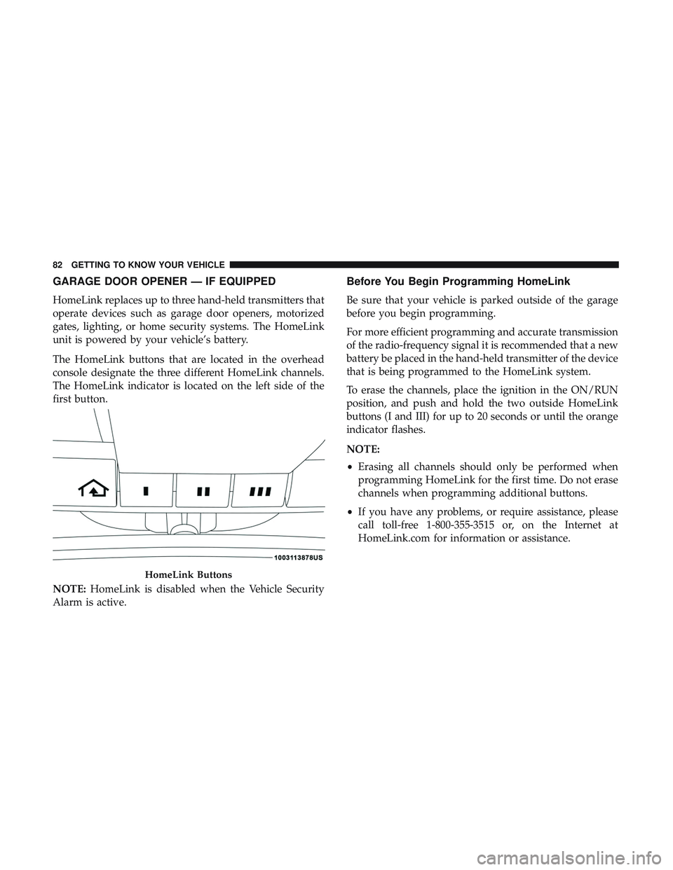
The HomeLink buttons that are located in the overhead
console designate the three different HomeLink channels.
The HomeLink indicator is located on the left side of the
first button.
NOTE:HomeLink is disabled when the Vehicle Security
Alarm is active.
Before You Begin Programming HomeLink
Be sure that your vehicle is parked outside of the garage
before you begin programming.
For more efficient programming and accurate transmission
of the radio-frequency signal it is recommended that a new
battery be placed in the hand-held transmitter of the device
that is being programmed to the HomeLink system.
To erase the channels, place the ignition in the ON/RUN
position, and push and hold the two outside HomeLink
buttons (I and III) for up to 20 seconds or until the orange
indicator flashes.
NOTE:
• Erasing all channels should only be performed when
programming HomeLink for the first time. Do not erase
channels when programming additional buttons.
• If you have any problems, or require assistance, please
call toll-free 1-800-355-3515 or, on the Internet at
HomeLink.com for information or assistance.
HomeLink Buttons
82 GETTING TO KNOW YOUR VEHICLE
Page 89 of 516

Security
It is advised to erase all channels before you sell or turn in
your vehicle.
To do this, push and hold the two outside buttons for 20
seconds until the orange indicator flashes. Note that all
channels will be erased. Individual channels cannot be
erased.
The HomeLink Universal Transceiver is disabled when the
Vehicle Security Alarm is active.
Troubleshooting Tips
If you are having trouble programming HomeLink, here
are some of the most common solutions:
•Replace the battery in the Garage Door Opener hand-
held transmitter.
• Push the LEARN button on the Garage Door Opener to
complete the training for a Rolling Code.
• Did you unplug the device for programming and
remember to plug it back in? If you have any problems, or require assistance, please call
toll-free 1-800-355-3515 or, on the Internet at
HomeLink.com for information or assistance.
WARNING!
•
Vehicle exhaust contains carbon monoxide, a danger-
ous gas. Do not run your vehicle in the garage while
programming the transceiver. Exhaust gas can cause
serious injury or death.
• Your motorized door or gate will open and close
while you are programming the universal trans-
ceiver. Do not program the transceiver if people, pets
or other objects are in the path of the door or gate.
Only use this transceiver with a garage door opener
that has a “stop and reverse” feature as required by
Federal safety standards. This includes most garage
door opener models manufactured after 1982. Do not
use a garage door opener without these safety fea-
tures. Call toll-free 1-800-355-3515 or, on the Internet
at HomeLink.com for safety information or assis-
tance.
3
GETTING TO KNOW YOUR VEHICLE 87
Page 93 of 516

convenient access to beverage cans or bottles while main-
taining a resting place for the rear occupant’s elbows.
Electrical Power Outlets
Your vehicle is equipped with 12 Volt (13 Amp) power
outlets that can be used to power cellular phones, small
electronics and other low powered electrical accessories.
The power outlets are labeled with either a “key” or a
“battery” symbol to indicate how the outlet is powered.
Power outlets labeled with a “key” can be powered when
the ignition is in the ON or ACC position, while the outlets
labeled with a “battery” are connected directly to the
battery and powered at all times.These power outlets can also operate a conventional cigar
lighter unit.
NOTE:
•
The front integrated center stack power outlet can be
changed from switched “ignition” to constant “battery”
powered all the time by moving the integrated center
stack fuse #12 in the Rear Power Distribution Center
from fuse location “IGN” to “B+.” Refer to “Fuses” in
“In Case Of Emergency.”
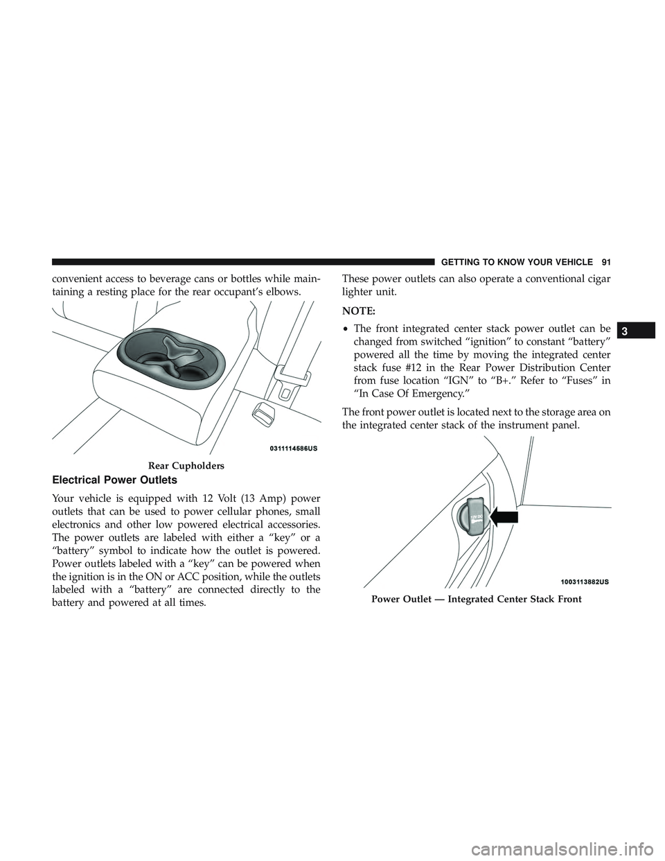
The front power outlet is located next to the storage area on
the integrated center stack of the instrument panel.
Rear Cupholders
Power Outlet — Integrated Center Stack Front
3
GETTING TO KNOW YOUR VEHICLE 91
Page 94 of 516

NOTE:All accessories connected to these powered outlets
should be removed or turned off when the vehicle is not in
use to protect the battery against discharge.
WARNING!
To avoid serious injury or death:
• Only devices designed for use in this type of outlet
should be inserted into any 12 Volt outlet.
• Do not touch with wet hands.
(Continued)
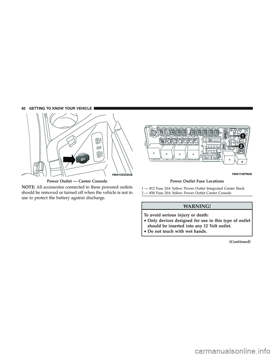
Power Outlet — Center ConsolePower Outlet Fuse Locations
1 — #12 Fuse 20A Yellow Power Outlet Integrated Center Stack
2 — #38 Fuse 20A Yellow Power Outlet Center Console
92 GETTING TO KNOW YOUR VEHICLE
Page 95 of 516

WARNING!(Continued)
•Close the lid when not in use and while driving the
vehicle.
• If this outlet is mishandled, it may cause an electric
shock and failure.
CAUTION!
• Do not exceed the maximum power of 160 Watts
(13 Amps) at 12 Volts. If the 160 Watt (13 Amp) power
rating is exceeded the fuse protecting the system will
need to be replaced.
•
Power outlets are designed for accessory plugs only.
Do not insert any other object in the power outlets as
this will damage the outlet and blow the fuse. Im-
proper use of the power outlet can cause damage not
covered by your New Vehicle Limited Warranty.
CAUTION!
• Many accessories that can be plugged in draw power
from the vehicle’s battery, even when not in use (i.e.,
cellular phones, etc.). Eventually, if plugged in long
(Continued)
CAUTION! (Continued)
enough, the vehicle’s battery will discharge suffi-
ciently to degrade battery life and/or prevent the
engine from starting.
• Accessories that draw higher power (i.e., coolers,
vacuum cleaners, lights, etc.), will degrade the bat-
tery even more quickly. Only use these intermit-
tently and with greater caution.
• After the use of high power draw accessories, or long
periods of the vehicle not being started (with acces-
sories still plugged in), the vehicle must be driven a
sufficient length of time to allow the alternator to
recharge the vehicle’s battery.
• Power outlets are designed for accessory plugs only.
Do not hang any type of accessory or accessory
bracket from the plug. Improper use of the power
outlet can cause damage.
3
GETTING TO KNOW YOUR VEHICLE 93
Page 105 of 516

•Oil Pressure
• Oil Life
• Battery Voltage
Driver Assist — If Equipped
Adaptive Cruise Control (ACC) Menu
The instrument cluster display displays the current ACC
system settings. The information displayed depends on
ACC system status.
Push the ADAPTIVE CRUISE CONTROL (ACC) ON/OFF
button (located on the steering wheel) until one of the
following displays in the instrument cluster display:
Adaptive Cruise Control Off
When ACC is deactivated, the display will read “Adaptive
Cruise Control Off.”
Adaptive Cruise Control Ready
When ACC is activated but the vehicle speed setting has
not been selected, the display will read “Adaptive Cruise
Control Ready.” Push the SET + or the SET- button (located on the steering
wheel) and the following will display in the instrument
cluster display:
ACC SET
When ACC is set, the set speed will display in the
instrument cluster.
The ACC screen may display once again if any ACC
activity occurs, which may include any of the following:
•
Distance Setting Change
• System Cancel
• Driver Override
• System Off
• ACC Proximity Warning
• ACC Unavailable Warning
• The instrument cluster display will return to the last
display selected after five seconds of no ACC display
activity.
For further information, refer to “Adaptive Cruise Control
(ACC) — If Equipped” in “Starting And Operating.”
4
GETTING TO KNOW YOUR INSTRUMENT PANEL 103
Page 108 of 516

6. Gear Display•Full (default)
• Single
7. Restore Defaults •Ok
• Cancel
Battery Saver On/Battery Saver Mode Message —
Electrical Load Reduction Actions — If Equipped
This vehicle is equipped with an Intelligent Battery Sensor
(IBS) to perform additional monitoring of the electrical
system and status of the vehicle battery.
In cases when the IBS detects charging system failure, or
the vehicle battery conditions are deteriorating, electrical
load reduction actions will take place to extend the driving
time and distance of the vehicle. This is done by reducing
power to or turning off non-essential electrical loads.
Load reduction is only active when the engine is running.
It will display a message if there is a risk of battery
depletion to the point where the vehicle may stall due to
lack of electrical supply, or will not restart after the current
drive cycle. When load reduction is activated, the message “Battery
Saver On” or “Battery Saver Mode” will appear in the
instrument cluster.
These messages indicate the vehicle battery has a low state
of charge and continues to lose electrical charge at a rate
that the charging system cannot sustain.
NOTE:
•
The charging system is independent from load reduc-
tion. The charging system performs a diagnostic on the
charging system continuously.
• If the Battery Charge Warning Light is on it may indicate
a problem with the charging system. Refer to “Battery
Charge Warning Light” in “Getting To Know Your
Instrument Panel” for further information.
The electrical loads that may be switched off (if equipped),
and vehicle functions which can be affected by load
reduction:
• Heated Seat/Vented Seats/Heated Wheel
• Heated/Cooled Cup Holders — If Equipped
• Rear Defroster And Heated Mirrors
• HVAC System
106 GETTING TO KNOW YOUR INSTRUMENT PANEL