2018 DODGE CHALLENGER run flat
[x] Cancel search: run flatPage 160 of 516

WARNING!(Continued)
•Do not use the Automatic Locking Mode to restrain
occupants who are wearing the seat belt or children
who are using booster seats. The locked mode is only
used to install rear-facing or forward-facing child
restraints that have a harness for restraining the
child.
Supplemental Restraint Systems (SRS)
Some of the safety features described in this section may be
standard equipment on some models, or may be optional
equipment on others. If you are not sure, ask your autho-
rized dealer.
The air bag system must be ready to protect you in a
collision. The Occupant Restraint Controller (ORC) moni-
tors the internal circuits and interconnecting wiring asso-
ciated with the electrical Air Bag System Components.
Your vehicle may be equipped with the following Air Bag
System Components:
Air Bag System Components
• Occupant Restraint Controller (ORC)
• Air Bag Warning Light
•Steering Wheel and Column
• Instrument Panel
• Knee Impact Bolsters
• Driver and Front Passenger Air Bags
• Seat Belt Buckle Switch
• Supplemental Side Air Bags
• Front and Side Impact Sensors
• Seat Belt Pretensioners
• Seat Track Position Sensors
Air Bag Warning Light
The ORC monitors the readiness of the electronic
parts of the air bag system whenever the ignition
switch is in the START or ON/RUN position. If
the ignition switch is in the OFF position or in the
ACC position, the air bag system is not on and the air bags
will not inflate.
The ORC contains a backup power supply system that may
deploy the air bag system even if the battery loses power or
it becomes disconnected prior to deployment.
158 SAFETY
Page 161 of 516

The ORC turns on the Air Bag Warning Light in the
instrument panel for approximately four to eight seconds
for a self-check when the ignition switch is first in the
ON/RUN position. After the self-check, the Air Bag Warn-
ing Light will turn off. If the ORC detects a malfunction in
any part of the system, it turns on the Air Bag Warning
Light, either momentarily or continuously. A single chime
will sound to alert you if the light comes on again after
initial startup.
The ORC also includes diagnostics that will illuminate the
instrument panel Air Bag Warning Light if a malfunction is
detected that could affect the air bag system. The diagnos-
tics also record the nature of the malfunction. While the air
bag system is designed to be maintenance free, if any of the
following occurs, have an authorized dealer service the air
bag system immediately.
•The Air Bag Warning Light does not come on during the
four to eight seconds when the ignition switch is first in
the ON/RUN position.
• The Air Bag Warning Light remains on after the four to
eight-second interval.
• The Air Bag Warning Light comes on intermittently or
remains on while driving. NOTE:
If the speedometer, tachometer, or any engine
related gauges are not working, the Occupant Restraint
Controller (ORC) may also be disabled. In this condition
the air bags may not be ready to inflate for your protection.
Have an authorized dealer service the air bag system
immediately.
WARNING!
Ignoring the Air Bag Warning Light in your instrument
panel could mean you won’t have the air bag system to
protect you in a collision. If the light does not come on
as a bulb check when the ignition is first turned on,
stays on after you start the vehicle, or if it comes on as
you drive, have an authorized dealer service the air bag
system immediately.
Redundant Air Bag Warning Light
If a fault with the Air Bag Warning Light is
detected, which could affect the Supplemental
Restraint System (SRS), the Redundant Air Bag
Warning Light will illuminate on the instrument
panel. The Redundant Air Bag Warning Light will stay on
until the fault is cleared. In addition, a single chime will
sound to alert you that the Redundant Air Bag Warning
5
SAFETY 159
Page 172 of 516

WARNING!(Continued)
bumper, vehicle body structure, or add aftermarket
side steps or running boards.
• It is dangerous to try to repair any part of the air bag
system yourself. Be sure to tell anyone who works on
your vehicle that it has an air bag system.
• Do not attempt to modify any part of your air bag
system. The air bag may inflate accidentally or may
not function properly if modifications are made.
Take your vehicle to an authorized dealer for any air
bag system service. If your seat, including your trim
cover and cushion, needs to be serviced in any way
(including removal or loosening/tightening of seat
attachment bolts), take the vehicle to an authorized
dealer. Only manufacturer approved seat accessories
may be used. If it is necessary to modify the air bag
system for persons with disabilities, contact an au-
thorized dealer.
Event Data Recorder (EDR)
This vehicle is equipped with an event data recorder
(EDR). The main purpose of an EDR is to record, in certain
crash or near crash-like situations, such as an air bag
deployment or hitting a road obstacle, data that will assist
in understanding how a vehicle’s systems performed. The
EDR is designed to record data related to vehicle dynamics
and safety systems for a short period of time, typically 30
seconds or less. The EDR in this vehicle is designed to
record such data as:
• How various systems in your vehicle were operating;
• Whether or not the driver and passenger safety belts
were buckled/fastened;
• How far (if at all) the driver was depressing the accel-
erator and/or brake pedal; and,
• How fast the vehicle was traveling.
These data can help provide a better understanding of the
circumstances in which crashes and injuries occur.
170 SAFETY
Page 192 of 516

WARNING!(Continued)
mat for the specific make, model, and year of your
vehicle.
• ONLY use the driver ’s side floor mat on the driver ’s
side floor area. To check for interference, with the
vehicle properly parked with the engine off, fully
depress the accelerator, the brake, and the clutch
pedal (if present) to check for interference. If your
floor mat interferes with the operation of any pedal,
or is not secure to the floor, remove the floor mat
from the vehicle and place the floor mat in your
trunk.
• ONLY use the passenger ’s side floor mat on the
passenger ’s side floor area.
• ALWAYS make sure objects cannot fall or slide into
the driver ’s side floor area when the vehicle is
moving. Objects can become trapped under accelera-
tor, brake, or clutch pedals and could cause a loss of
vehicle control.
• NEVER place any objects under the floor mat (e.g.,
towels, keys, etc.). These objects could change the
position of the floor mat and may cause interference
with the accelerator, brake, or clutch pedals.
(Continued)
WARNING! (Continued)
•If the vehicle carpet has been removed and re-
installed, always properly attach carpet to the floor
and check the floor mat fasteners are secure to the
vehicle carpet. Fully depress each pedal to check for
interference with the accelerator, brake, or clutch
pedals then re-install the floor mats.
• It is recommended to only use mild soap and water
to clean your floor mats. After cleaning, always check
your floor mat has been properly installed and is
secured to your vehicle using the floor mat fasteners
by lightly pulling mat.
Periodic Safety Checks You Should Make Outside
The Vehicle
Tires
Examine tires for excessive tread wear and uneven wear
patterns. Check for stones, nails, glass, or other objects
lodged in the tread or sidewall. Inspect the tread for cuts
and cracks. Inspect sidewalls for cuts, cracks, and bulges.
Check the wheel nuts for tightness. Check the tires (includ-
ing spare) for proper cold inflation pressure.
190 SAFETY
Page 263 of 516

Towing Tips
Before setting out on a trip, practice turning, stopping, and
backing up the trailer in an area located away from heavy
traffic.
Automatic Transmission — If Equipped
Select the DRIVE range when towing. The transmission
controls include a drive strategy to avoid frequent shifting
when towing. However, if frequent shifting does occur
while in DRIVE, you can use the AutoStick shift control to
manually select a lower gear.
NOTE:Using a lower gear while operating the vehicle
under heavy loading conditions will improve performance
and extend transmission life by reducing excessive shifting
and heat buildup. This action will also provide better
engine braking.
Speed Control — If Equipped
• Do not use on hilly terrain or with heavy loads.
• When using the speed control, if you experience speed
drops greater than 10 mph (16 km/h), disengage until
you can get back to cruising speed.
• Use speed control in flat terrain and with light loads to
maximize fuel efficiency.
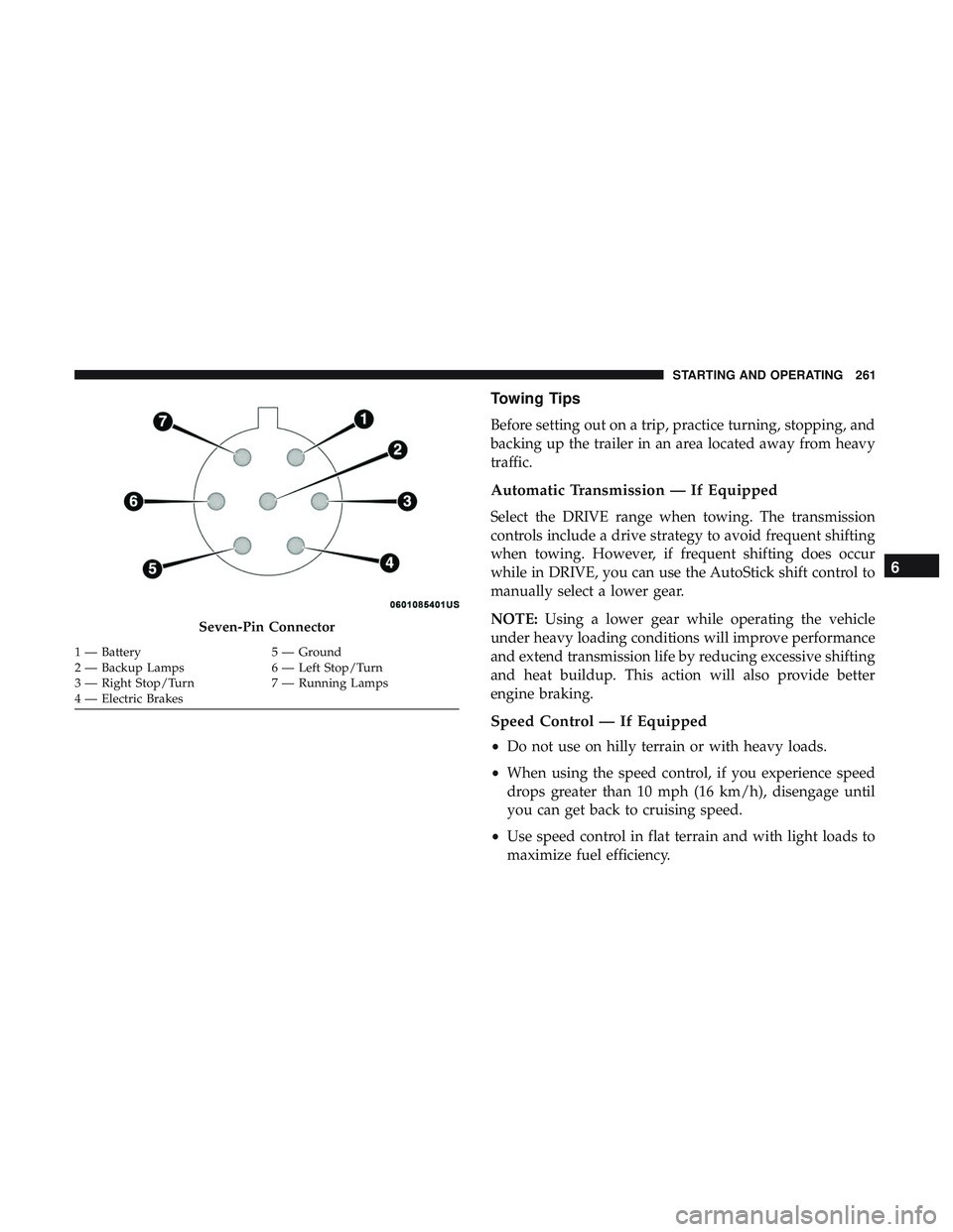
Seven-Pin Connector
1 — Battery 5 — Ground
2 — Backup Lamps 6 — Left Stop/Turn
3 — Right Stop/Turn 7 — Running Lamps
4 — Electric Brakes
6
STARTING AND OPERATING 261
Page 300 of 516

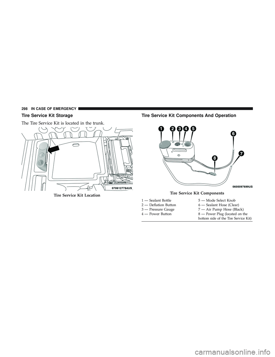
Tire Service Kit Storage
The Tire Service Kit is located in the trunk.
Tire Service Kit Components And Operation
Tire Service Kit LocationTire Service Kit Components
1 — Sealant Bottle5 — Mode Select Knob
2 — Deflation Button 6 — Sealant Hose (Clear)
3 — Pressure Gauge 7 — Air Pump Hose (Black)
4 — Power Button 8 —
Power Plug (located on the
bottom side of the Tire Service Kit)
298 IN CASE OF EMERGENCY
Page 303 of 516

WARNING!(Continued)
in injuries that are serious or fatal to you, your
passengers, and others around you.
• Take care not to allow the contents of Tire Service Kit
to come in contact with hair, eyes, or clothing. Tire
Service Kit sealant is harmful if inhaled, swallowed,
or absorbed through the skin. It causes skin, eye, and
respiratory irritation. Flush immediately with plenty
of water if there is any contact with eyes or skin.
Change clothing as soon as possible, if there is any
contact with clothing.
• Tire Service Kit Sealant solution contains latex. In
case of an allergic reaction or rash, consult a physi-
cian immediately. Keep Tire Service Kit out of reach
of children. If swallowed, rinse mouth immediately
with plenty of water and drink plenty of water. Do
not induce vomiting! Consult a physician immedi-
ately.
Sealing A Tire With Tire Service Kit
(A) Whenever You Stop To Use Tire Service Kit:
1. Pull over to a safe location and turn on the vehicle’s Hazard Warning flashers. 2. Verify that the valve stem (on the wheel with the
deflated tire) is in a position that is near to the ground.
This will allow the Tire Service Kit Hoses (6) and (7) to
reach the valve stem and keep the Tire Service Kit flat on
the ground. This will provide the best positioning of the
kit when injecting the sealant into the deflated tire and
running the air pump. Move the vehicle as necessary to
place the valve stem in this position before proceeding.
3. Place the transmission in PARK (auto transmission) or in Gear (manual transmission) and place the ignition in the
OFF position.
4. Apply the parking brake.
(B) Setting Up To Use Tire Service Kit:
1. Push in the Mode Select Knob (5) and turn to the Sealant Mode position.
2. Uncoil the Sealant Hose (6) and then remove the cap from the fitting at the end of the hose.
3. Place the Tire Service Kit flat on the ground next to the deflated tire.
4. Remove the cap from the valve stem and then screw the fitting at the end of the Sealant Hose (6) onto the valve
stem.
7
IN CASE OF EMERGENCY 301
Page 304 of 516

5. Uncoil the Power Plug (8) and insert the plug into thevehicle’s 12 Volt power outlet.
NOTE: Do not remove foreign objects (e.g., screws or
nails) from the tire.
(C) Injecting Tire Service Kit Sealant Into The
Deflated Tire:
• Always start the engine before turning ON the Tire
Service Kit.
NOTE: Manual transmission vehicles must have the park-
ing brake engaged and the gear selector in NEUTRAL.
• After pushing the Power Button (4), the sealant (white
fluid) will flow from the Sealant Bottle (1) through the
Sealant Hose (6) and into the tire.
NOTE: Sealant may leak out through the puncture in the
tire.
If the sealant (white fluid) does not flow within0–10
seconds through the Sealant Hose (6):
1. Push the Power Button (4) to turn Off the Tire Service Kit. Disconnect the Sealant Hose (6) from the valve stem.
Make sure the valve stem is free of debris. Reconnect the
Sealant Hose (6) to the valve stem. Check that the Mode Select Knob (5) is in the Sealant Mode position and not
Air Mode. Push the Power Button (4) to turn On the Tire
Service Kit.
2. Connect the Power Plug (8) to a different 12 Volt power outlet in your vehicle or another vehicle, if available.
Make sure the engine is running before turning ON the
Tire Service Kit.
3. The Sealant Bottle (1) may be empty due to previous use. Call for assistance.
NOTE: If the Mode Select Knob (5) is on Air Mode and the
pump is operating, air will dispense from the Air Pump
Hose (7) only, not the Sealant Hose (6).
If the sealant (white fluid) does flow through the Sealant
Hose (6):
1.
Continue to operate the pump until sealant is no longer
flowing through the hose (typically takes 30 - 70 seconds).
As the sealant flows through the Sealant Hose (6), the
Pressure Gauge (3) can read as high as 70 psi (4.8 Bar). The
Pressure Gauge (3) will decrease quickly from approxi-
mately 70 psi (4.8 Bar) to the actual tire pressure when the
Sealant Bottle (1) is empty.
302 IN CASE OF EMERGENCY