2018 CITROEN DS3 glove box
[x] Cancel search: glove boxPage 6 of 248

4
Instruments and controls3
Dashboard fuses
4
Rear view mirror
Courtesy lamp
Active City Brake
5
Monochrome screen A
Monochrome screen C
Audio system
Touch screen tablet
Adjust date and time
6
Ventilation
Heating
Manual air conditioning
Automatic air conditioning
Front demisting/defrosting
Rear screen demisting/defrosting
7
Manual gearbox
Electronic gearbox (ETG)
Automatic gearbox
Stop & Start
8
Centre armrest
Parking brake
9
Glove box
10
Emergency or Assistance call
Hazard warning lamps
1
Door mirror controls
Electric window controls
2
Bonnet opening control
Over view
Page 24 of 248

22
Warning/indicator lampStateCause Action/Observations
Passenger's
airbag system Fixed.
The control switch, located in
the glove box, is set to the " OFF"
position.
The passenger's front airbag is
deactivated.
You can install a "rearward" facing
child seat, unless there is a
fault with
the airbags (airbag warning lamp on). To activate the passenger front airbag, turn the
control to the "
ON" position.
In this case, do not fit a
child seat in the "rear ward"
facing position.
Stop & Star t Fixed.
When the vehicle stops (red lights, traffic
jams, etc.) the Stop & Start system puts
the engine into STOP mode.The warning lamp goes off and the engine restarts
automatically in START mode, as soon as you want
to move off.
Flashes for a
few
seconds, then goes
of f. STOP mode is temporarily
unavailable.
or
START mode is triggered
automatically. For more information on Stop & Star t
, refer to the
corresponding section.
Left-hand
direction
indicator Flashing with audible
signal.
The lighting control stalk has been
moved down.
Right-hand
direction
indicator Flashing with audible
signal.
The lighting control stalk has been
moved up.
Automatic
wiping
Fixed.
The wiper control stalk has been
pushed down. Automatic front wiping is activated.
01
Instruments
Page 80 of 248

78
Switching off
The mood lighting switches off automatically
when the sidelamps are switched off.
It can be switched off manually by using the
lighting dimmer button on the instrument panel.
F
W
ith the lamps on, press the left-hand
button on the instrument panel several
times to progressively reduce the brightness
of the instruments and controls.
F
P
ress again to reduce the brightness to
a
minimum and switch off the mood lighting.
Programming
The function is activated or deactivated via the
vehicle configuration menu.
Interior fittings1.Sun visor
2. Illuminated glove box
3. Door pocket
4. Upper storage
5. Lower storage with anti-slip mat
6. USB por t /Jack auxiliar y socket
(see details on following pages)
7. 12
V accessory socket
8. Centre armrest and storage
or
Cup holder/Bottle holder
9. Storage compartments
Sun visor
The sun visors have a vanity mirror with flap
a nd a card holder (or ticket holder) for the
driver.
F
W
ith the ignition on, raise the concealing
flap; the mirror is illuminated automatically.
03
Ease of use and comfort
Page 81 of 248

79
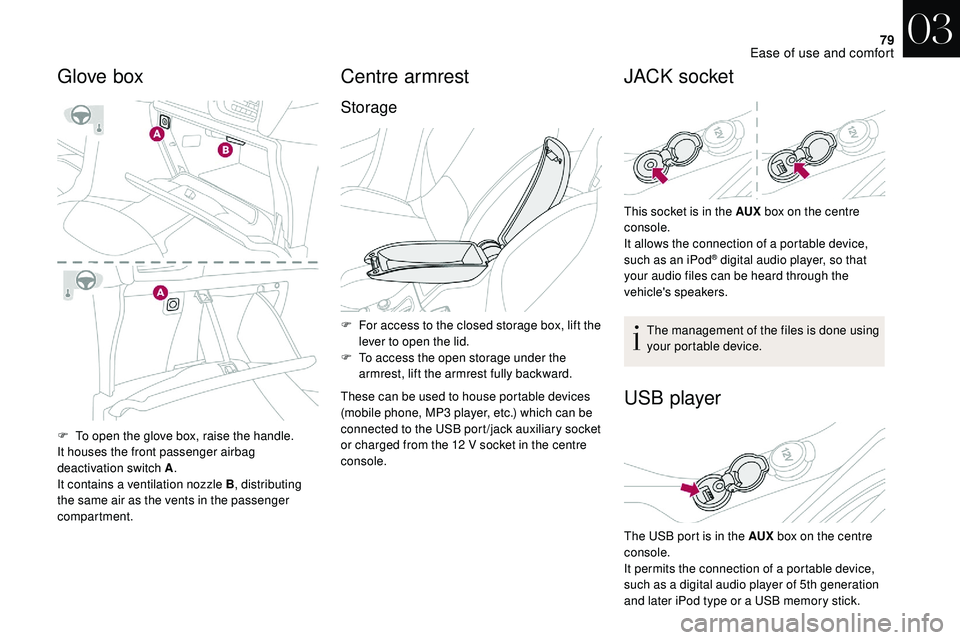
F To open the glove box, raise the handle.
It houses the front passenger airbag
deactivation switch A.
It contains a
ventilation nozzle B , distributing
the same air as the vents in the passenger
compartment.
Centre armrest
Storage
F For access to the closed storage box, lift the lever to open the lid.
F
T
o access the open storage under the
armrest, lift the armrest fully backward.
These can be used to house portable devices
(mobile phone, MP3
player, etc.) which can be
connected to the USB port /jack auxiliary socket
or charged from the 12
V socket in the centre
console.
JACK socket
Glove box
This socket is in the AUX box on the centre
console.
It allows the connection of a
portable device,
such as an
iPod
® digital audio player, so that
your audio files can be heard through the
vehicle's speakers.
The management of the files is done using
your portable device.
USB player
The USB port is in the AUX box on the centre
console.
It permits the connection of a
portable device,
such as a
digital audio player of 5th generation
and later iPod type or a
USB memory stick.
03
Ease of use and comfort
Page 103 of 248

101
Airbags
General information
This system contributes towards improving the
safety of passengers (with the exception of the
rear centre passenger) in the event of violent
collisions. The airbags supplement the action
of the seat belts fitted with force limiters (all
except the centre rear passenger belt).
If a collision occurs, the electronic detectors
record and analyse the front and side impacts
sustained in the impact detection zones:
-
i
n the event of a serious impact, the airbags
are deployed instantly and contribute
towards better protection of the passengers
(with the exception of the rear centre
passenger); immediately after the impact,
the airbags deflate rapidly so that they
do not hinder visibility or the exit of the
passengers,
-
i
n the case of a minor or rear impact or in
certain roll-over conditions, the airbags
may not be deployed; the seat belt
alone contributes towards ensuring your
protection in these situations. The airbags do not operate when the
ignition is switched off.
This equipment will only deploy once. If
a
second impact occurs (during the same
or a subsequent accident), the airbag will
not be deployed again.
Impact detection zones
A. Front impact zone.
B. Side impact zone. The deployment of an airbag is
accompanied by a
slight emission of
smoke and a noise, due to the detonation
of the pyrotechnic charge incorporated in
the system.
This smoke is not harmful, but sensitive
individuals may experience slight irritation.
The detonation noise associated with the
deployment of an airbag may result in
a slight loss of hearing for a short time.
Front airbags
System which protects the driver and front
passenger in the event of a
serious front impact
in order to limit the risk of injury to the head and
chest.
The driver's airbag is fitted in the centre of the
steering wheel; the front passenger's airbag is
fitted in the dashboard above the glove box.
05
Safety
Page 171 of 248

169
If a pressure of 2 bars is not reached after
7 minutes, this indicates that the tyre is
not repairable; contact your dealer or
a
qualified workshop for recovery.
F
O
nce the correct pressure is reached, put
the switch to the " O" position.
F
R
emove the kit then stow it.
Do not drive more than 120
miles (200 km)
with a
temporarily repaired tyre; see your
dealer or a
qualified workshop to change
the tyre.
Should the pressure of one or more tyres
be adjusted, it is necessary to reinitialise
the under-inflation detection system.
For more information on Under-inflation
detection , refer to the corresponding
section.
Spare wheel
Scan the QR code on page 3 to view
e xplanatory videos.
Procedure for changing a
damaged wheel with
the spare wheel using the tools provided with
the vehicle.
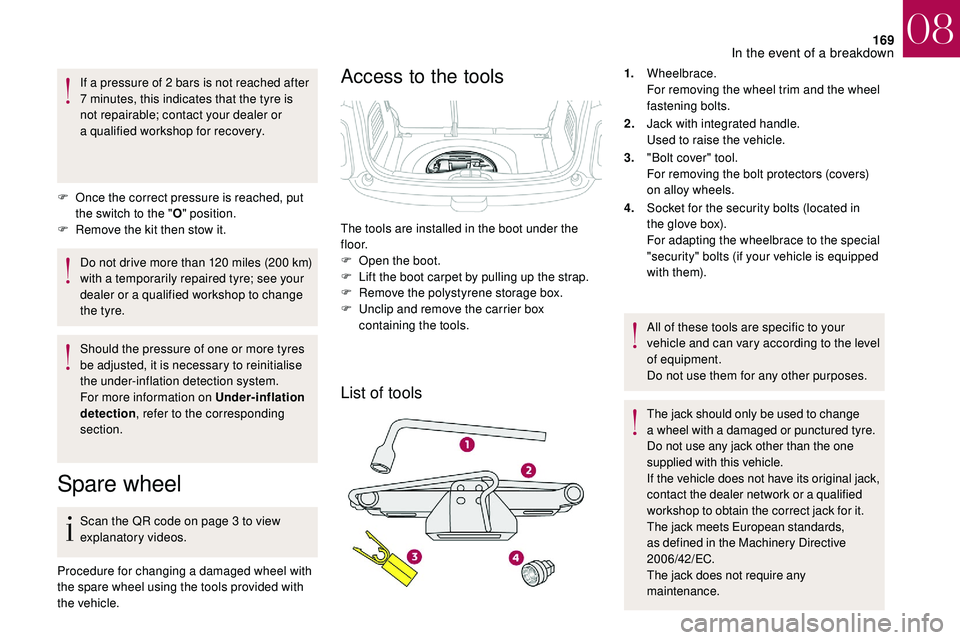
Access to the tools
List of tools
1. Wheelbrace.
For removing the wheel trim and the wheel
fastening bolts.
2. Jack with integrated handle.
Used to raise the vehicle.
3. "Bolt cover" tool.
For removing the bolt protectors (covers)
on alloy wheels.
4. Socket for the security bolts (located in
the glove box).
For adapting the wheelbrace to the special
"security" bolts (if your vehicle is equipped
with them).
All of these tools are specific to your
vehicle and can vary according to the level
of equipment.
Do not use them for any other purposes.
The jack should only be used to change
a
wheel with a damaged or punctured tyre.
Do not use any jack other than the one
supplied with this vehicle.
If the vehicle does not have its original jack,
contact the dealer network or a
qualified
workshop to obtain the correct jack for it.
The jack meets European standards,
as defined in the Machinery Directive
2006/42/EC.
The jack does not require any
maintenance.
The tools are installed in the boot under the
f l o o r.
F
O
pen the boot.
F
L
ift the boot carpet by pulling up the strap.
F
R
emove the polystyrene storage box.
F
U
nclip and remove the carrier box
containing the tools.
08
In the event of a breakdown
Page 182 of 248

180
Interior lighting
Courtesy lamp (1/W5W)
Unclip the cover of courtesy lamp 1 with a fine
s crewdriver, on the control side, to access the
faulty bulb.
Map reading lamps (2/W5W)
Unclip the cover of courtesy lamp 1 . To
access the faulty bulb, unclip the reading lamp
2
partition concerned.
Boot lamp (W5W) Footwell and central storage lighting
(W5W)
Unclip the unit to access the bulb.
Glove box lighting (W5W)Unclip the unit by pushing the base from
behind.
Unclip the unit to access the bulb.
08
In the event of a breakdown
Page 183 of 248

181
Changing a fuse
Access to the tools
The extraction tweezers and the locations for
spare fuses are installed behind the fusebox
cover on the dashboard.
Changing a fuse
F always replace the defective fuse with
a fuse of the same rating (same colour);
using a
different rating could cause
a
malfunction (risk of fire).
If the fault recurs after replacing a
fuse, have
the electrical system checked in the dealer
network or by a
qualified workshop.
Replacement with a
fuse not shown in
the allocation tables below may cause
a
serious malfunction of your vehicle.
Contact the dealer network or a
qualified
workshop.
F
U
nclip the fusebox cover by pulling the side.
F
R
emove the cover completely,
F
P
ull out the tweezers.
F
O
pen the glove box lid.
F
U
nclip the fusebox cover by pulling the side.
F
R
emove the cover completely,
F
P
ull out the tweezers.
Before changing a
fuse:
F
t
he cause of the failure must be identified
and rectified,
F
a
ll electrical consumers must be switched
of f,
F
s
top the vehicle and switch off the ignition,
F
I
dentify the faulty fuse using the existing
allocation tables and diagrams given in the
following pages.
To replace a
fuse, you must:
F
u
se the special tweezers to extract the fuse
from its housing and check the condition of
its filament, Good
Failed
Tw e e z e r s
08
In the event of a breakdown