Page 404 of 696

Modes Of Operation
“Manual” activation of the Rear View display is selected by
pressing the Back Up Camera soft key located in the
“Controls” screen within the Uconnect system.
Top View
The Top view will show in the Uconnect System with Rear
View and Front View in a split view display. There is
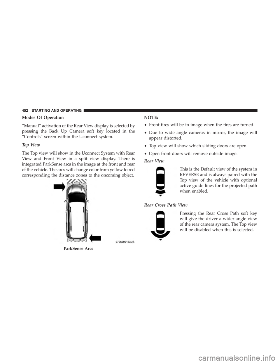
integrated ParkSense arcs in the image at the front and rear
of the vehicle. The arcs will change color from yellow to red
corresponding the distance zones to the oncoming object.NOTE:
•
Front tires will be in image when the tires are turned.
• Due to wide angle cameras in mirror, the image will
appear distorted.
• Top view will show which sliding doors are open.
• Open front doors will remove outside image.
Rear View
This is the Default view of the system in
REVERSE and is always paired with the
Top view of the vehicle with optional
active guide lines for the projected path
when enabled.
Rear Cross Path View Pressing the Rear Cross Path soft key
will give the driver a wider angle view
of the rear camera system. The Top view
will be disabled when this is selected.
ParkSense Arcs
402 STARTING AND OPERATING
Page 408 of 696

Gross Vehicle Weight Rating (GVWR)
The GVWR is the total permissible weight of your vehicle
including driver, passengers, vehicle, options and cargo.
The label also specifies maximum capacities of front and
rear axle systems (GAWR). Total load must be limited so
GVWR and front and rear GAWR are not exceeded.
Payload
The payload of a vehicle is defined as the allowable load
weight a truck can carry, including the weight of the driver,
all passengers, options and cargo.
Gross Axle Weight Rating (GAWR)
The GAWR is the maximum permissible load on the front
and rear axles. The load must be distributed in the cargo
area so that the GAWR of each axle is not exceeded.
Each axle GAWR is determined by the components in the
system with the lowest load carrying capacity (axle,
springs, tires or wheels). Heavier axles or suspension
components sometimes specified by purchasers for in-
creased durability does not necessarily increase the vehi-
cle’s GVWR.
Tire Size
The tire size on the Vehicle Certification Label represents
the actual tire size on your vehicle. Replacement tires must
be equal to the load capacity of this tire size.
Rim Size
This is the rim size that is appropriate for the tire size
listed.
Inflation Pressure
This is the cold tire inflation pressure for your vehicle for
all loading conditions up to full GAWR.
Curb Weight
The curb weight of a vehicle is defined as the total weight
of the vehicle with all fluids, including vehicle fuel, at full
capacity conditions, and with no occupants or cargo loaded
into the vehicle. The front and rear curb weight values are
determined by weighing your vehicle on a commercial
scale before any occupants or cargo are added.
Loading
The actual total weight and the weight of the front and rear
of your vehicle at the ground can best be determined by
weighing it when it is loaded and ready for operation.
406 STARTING AND OPERATING
Page 413 of 696
NOTE:The trailer tongue weight must be considered as
part of the combined weight of occupants and cargo, and
should never exceed the weight referenced on the Tire and
Loading Information placard. Refer to “Tires” in “Servicing
And Maintenance” for further information.
Vehicle Loading Chart
Follow these steps to determine the total weight the vehicle
can carry.
1. Determine the cargo capacity of your vehicle.
•Load Capacity = GVWR – Curb (weight of vehicle full
fluids NO Occupants).
2. Determine occupant count. •For calculation purposes, average weight of an occu-
pant is 150 lb (68 kg). EXAMPLE:
•
GVWR = 6005 lbs (2723 kg)
• CURB = 4500 lbs (2041 kg)
• Load Capacity = GVWR – CURB = 6005 lbs (2723 kg) -
4500 lbs (2041 kg) = 1505 lbs (682 kg)
4 Occupants (at 150 lbs [68 kg]) + Max Trailer =
• 1505 lbs (682 kg) – 600 lbs (272 kg) (4 x 150 lbs [68 kg])
– 360 lbs (163 kg) (10% of 3600 lbs [1632 kg]) = 545 lbs
(247 kg) of cargo in vehicle
6
STARTING AND OPERATING 411
Page 416 of 696

Maintenance” for the proper maintenance intervals. When
towing a trailer, never exceed the GAWR or GCWR ratings.
WARNING!
Improper towing can lead to a collision. Follow these
guidelines to make your trailer towing as safe as
possible:
•Make certain that the load is secured in the trailer
and will not shift during travel. When trailering
cargo that is not fully secured, dynamic load shifts
can occur that may be difficult for the driver to
control. You could lose control of your vehicle and
have a collision.
• When hauling cargo or towing a trailer, do not
overload your vehicle or trailer. Overloading can
cause a loss of control, poor performance or damage
to brakes, axle, engine, transmission, steering, sus-
pension, chassis structure or tires.
• Safety chains must always be used between your
vehicle and trailer. Always connect the chains to the
hook retainers of the vehicle hitch. Cross the chains
under the trailer tongue and allow enough slack for
turning corners.
(Continued)
WARNING! (Continued)
•Vehicles with trailers should not be parked on a
grade. When parking, apply the parking brake on the
tow vehicle. Put the tow vehicle transmission in
PARK. For four-wheel drive vehicles, make sure the
transfer case is not in NEUTRAL. Always, block or
�chock� the trailer wheels.
• GCWR must not be exceeded.
• Total weight must be distributed between the tow
vehicle and the trailer such that the following four
ratings are not exceeded:
1. GVWR
2. GTW
3. GAWR
4. Tongue weight rating for the trailer hitch utilized.
Towing Requirements — Tires
• Do not attempt to tow a trailer while using a compact
spare tire.
• Do not drive more than 50 mph (80 km/h) when towing
while using a full size spare tire.
414 STARTING AND OPERATING
Page 417 of 696

•Proper tire inflation pressures are essential to the safe
and satisfactory operation of your vehicle. Refer to
“Tires” in “Servicing And Maintenance” for proper tire
inflation procedures.
• Check the trailer tires for proper tire inflation pressures
before trailer usage.
• Check for signs of tire wear or visible tire damage before
towing a trailer. Refer to “Tires” in “Servicing And
Maintenance” for the proper inspection procedure.
• When replacing tires, refer to “Tires” in “Servicing And
Maintenance” for the proper tire replacement proce-
dures. Replacing tires with a higher load carrying capac-
ity will not increase the vehicle’s GVWR and GAWR
limits.
Towing Requirements — Trailer Brakes
•Do not interconnect the hydraulic brake system or
vacuum system of your vehicle with that of the trailer.
This could cause inadequate braking and possible per-
sonal injury.
• An electronically actuated trailer brake controller is
required when towing a trailer with electronically actu-
ated brakes. When towing a trailer equipped with a hydraulic surge actuated brake system, an electronic
brake controller is not required.
• Trailer brakes are recommended for trailers over
1,000 lbs (453 kg) and required for trailers in excess of
2,000 lbs (907 kg).
WARNING!
•Do not connect trailer brakes to your vehicle’s hy-
draulic brake lines. It can overload your brake sys-
tem and cause it to fail. You might not have brakes
when you need them and could have a collision.
• Towing any trailer will increase your stopping dis-
tance. When towing you should allow for additional
space between your vehicle and the vehicle in front
of you. Failure to do so could result in a collision.
CAUTION!
If the trailer weighs more than 1,000 lbs (453 kg)
loaded, it should have its own brakes and they should
be of adequate capacity. Failure to do this could lead to
accelerated brake lining wear, higher brake pedal
effort, and longer stopping distances.
6
STARTING AND OPERATING 415
Page 422 of 696

Traction
When driving on wet or slushy roads, it is possible for a
wedge of water to build up between the tire and road
surface. This is hydroplaning and may cause partial or
complete loss of vehicle control and stopping ability. To
reduce this possibility, the following precautions should be
observed:
•Slow down during rainstorms or when the roads are
slushy.
• Slow down if the road has standing water or puddles.
• Replace the tires when tread wear indicators first be-
come visible.
• Keep tires properly inflated.
• Maintain sufficient distance between your vehicle and
the vehicle in front of you to avoid a collision in a
sudden stop.
Driving Through Water
Driving through water more than a few inches/centimeters
deep will require extra caution to ensure safety and pre-
vent damage to your vehicle.
Flowing/Rising Water
WARNING!
Do not drive on or across a road or path where water is
flowing and/or rising (as in storm run-off). Flowing
water can wear away the road or path’s surface and
cause your vehicle to sink into deeper water. Further-
more, flowing and/or rising water can carry your ve-
hicle away swiftly. Failure to follow this warning may
result in injuries that are serious or fatal to you, your
passengers, and others around you.
Shallow Standing Water
Although your vehicle is capable of driving through shal-
low standing water, consider the following Cautions and
Warnings before doing so.
WARNING!
•Driving through standing water limits your vehicle’s
traction capabilities. Do not exceed 5 mph (8 km/h)
when driving through standing water.
(Continued)
420 STARTING AND OPERATING
Page 448 of 696

JACKING AND TIRE CHANGING — IF EQUIPPED
WARNING!
•Do not attempt to change a tire on the side of the
vehicle close to moving traffic. Pull far enough off
the road to avoid the danger of being hit when
operating the jack or changing the wheel.
• Being under a jacked-up vehicle is dangerous. The
vehicle could slip off the jack and fall on you. You
could be crushed. Never put any part of your body
under a vehicle that is on a jack. If you need to get
under a raised vehicle, take it to a service center
where it can be raised on a lift.
• The jack is designed to be used as a tool for changing
tires only. The jack should not be used to lift the
vehicle for service purposes. The vehicle should be
jacked on a firm level surface only. Avoid ice or
slippery areas.
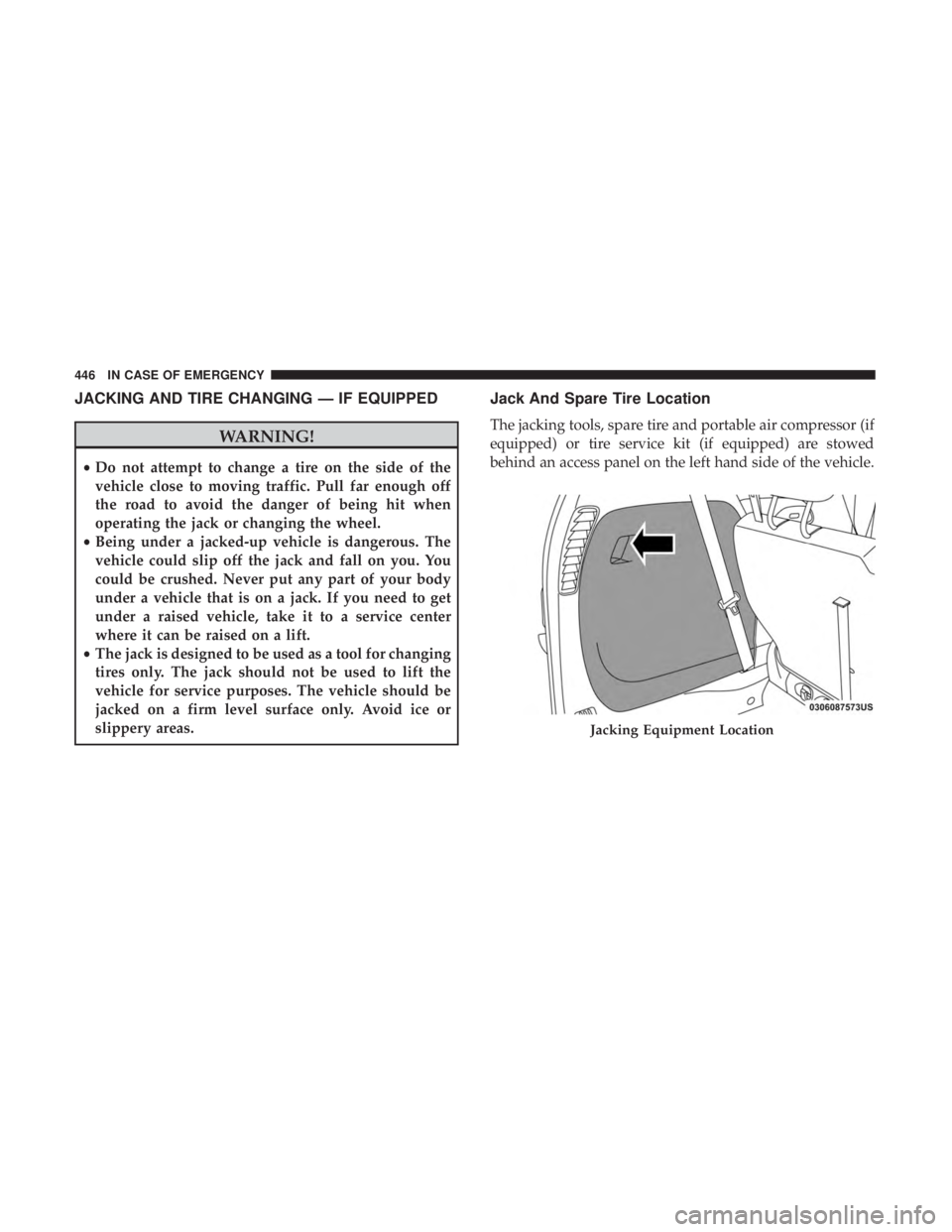
Jack And Spare Tire Location
The jacking tools, spare tire and portable air compressor (if
equipped) or tire service kit (if equipped) are stowed
behind an access panel on the left hand side of the vehicle.
Jacking Equipment Location
446 IN CASE OF EMERGENCY
Page 451 of 696
CAUTION!
Do not attempt to raise the vehicle by jacking on
locations other than those indicated in the Jacking
Instructions for this vehicle.
NOTE: Refer to “Tires” in “Servicing And Maintenance �for
information about the inflatable spare tire, its use, and
operation. 1. Loosen (but do not remove) the wheel lug nuts by
turning them to the left one turn while the wheel is still
on the ground.
2. There are two jack engagement locations on each side of the vehicle body. These locations are on the sill flange of
the vehicle body.
Jack Warning LabelExtending The Wrench
7
IN CASE OF EMERGENCY 449