2018 CHRYSLER PACIFICA HYBRID charging
[x] Cancel search: chargingPage 27 of 614
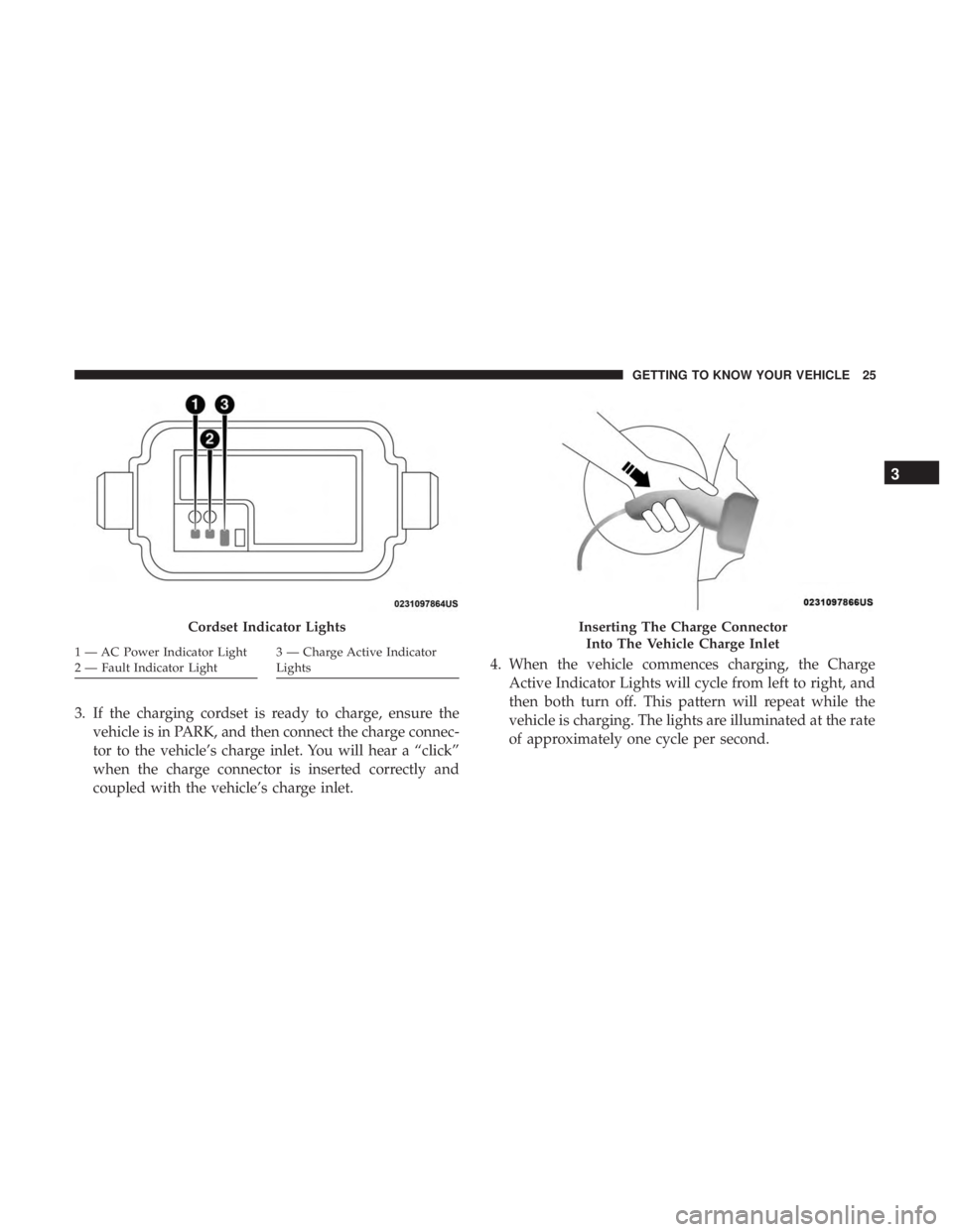
3. If the charging cordset is ready to charge, ensure thevehicle is in PARK, and then connect the charge connec-
tor to the vehicle’s charge inlet. You will hear a “click”
when the charge connector is inserted correctly and
coupled with the vehicle’s charge inlet. 4. When the vehicle commences charging, the Charge
Active Indicator Lights will cycle from left to right, and
then both turn off. This pattern will repeat while the
vehicle is charging. The lights are illuminated at the rate
of approximately one cycle per second.
Cordset Indicator Lights
1 — AC Power Indicator Light
2 — Fault Indicator Light3 — Charge Active Indicator
Lights
Inserting The Charge Connector
Into The Vehicle Charge Inlet
3
GETTING TO KNOW YOUR VEHICLE 25
Page 28 of 614
NOTE:The vehicle should start charging automatically. If
not, please check the following:
•Charging Cordset - The charging cordset status indi-
cators illuminate green or red to identify the charging
cordset status. Refer to “Troubleshooting Using The
Status Indicator Display” in this section for further
information on the charging cordset status.
• Wall Receptacle – Check whether the wall receptacle is
functional (no power outage) and/or plug the charg-
ing cordset into a different wall receptacle.
• Charging Schedule – Check whether or not the charg-
ing schedules have been enabled. If enabled, check
that you are within the scheduled time and day of the
week. If a charging schedule has been enabled in the
vehicle, and it is outside the time and day of the week,
you may override the schedule for this charging event
by plugging in the charge connector, unplugging it,
and then plugging it back into the vehicle charge inlet.
Complete the double plug sequence within ten sec-
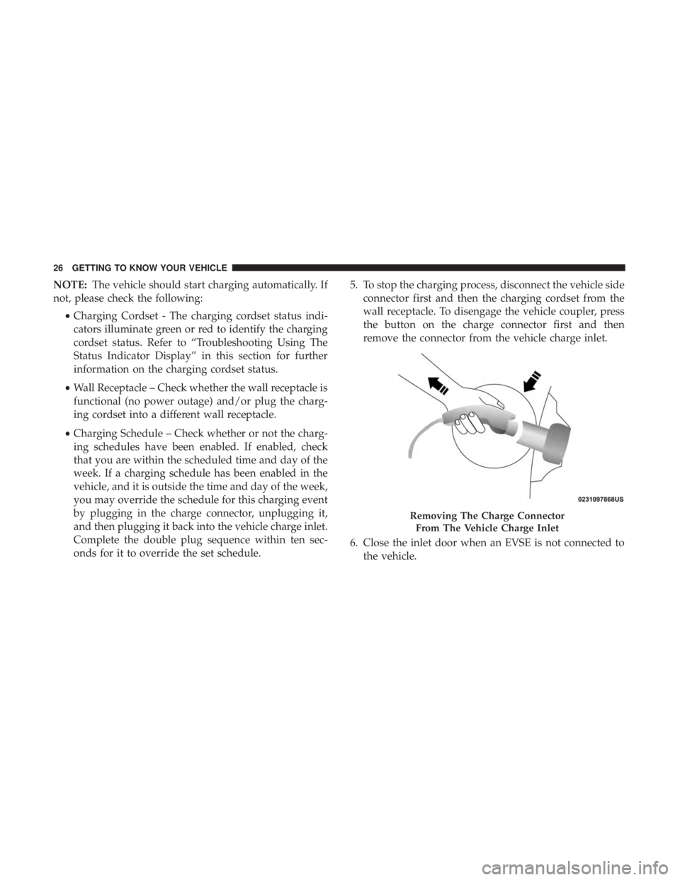
onds for it to override the set schedule. 5. To stop the charging process, disconnect the vehicle side
connector first and then the charging cordset from the
wall receptacle. To disengage the vehicle coupler, press
the button on the charge connector first and then
remove the connector from the vehicle charge inlet.
6. Close the inlet door when an EVSE is not connected to the vehicle.
Removing The Charge Connector
From The Vehicle Charge Inlet
26 GETTING TO KNOW YOUR VEHICLE
Page 29 of 614

NOTE:It is good practice to keep the ignition in the OFF
position while conducting Level 1 Charging. This mini-
mizes any additional vehicle loads the EVSE has to sup-
port. The additional electrical loads will extent the High
Voltage Battery charging time.
Troubleshooting Using The Status Indicator Display
If the vehicle is not charging properly, consult the status
indicator lights.
The AC Power Indicator displays the status and safety of
the input power. If this indicator is green, the power is
within acceptable limits to charge the vehicle. If only the
AC Power Indicator is flashing red, then there is a problem
with the AC power at the electrical outlet. If the AC Power
Indicator does not return to green, then the outlet should
be inspected by a licensed electrician to ensure the voltage,
frequency, and grounding are complaint to national and
local electrical codes and ordinances. It may be possible to
attempt charging from a different outlet.
The Fault Indicator displays the status of the Portable
EVSE Cordset and the vehicle connection. The Portable
EVSE Cordset will not allow charging while the fault
indicator is red. If it is off, the Portable EVSE Cordset has
not detected any internal faults, or faults with the vehicle
connection. If the Fault Indicator is flashing red, there is a fault detected either with the Portable EVSE Cordset,
electronics, or with the vehicle connection. The Portable
EVSE Cordset may attempt to retry to provide current to
the vehicle if the fault is cleared. If the Portable EVSE
Cordset does not attempt to provide charge to the vehicle,
the charge connector will need to be removed from the
vehicle to clear the fault.
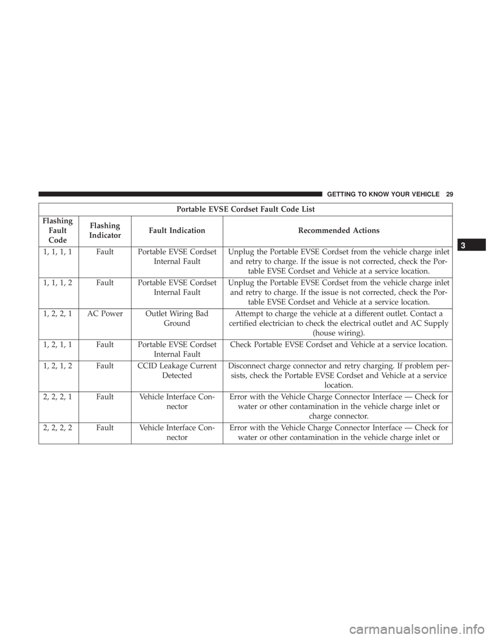
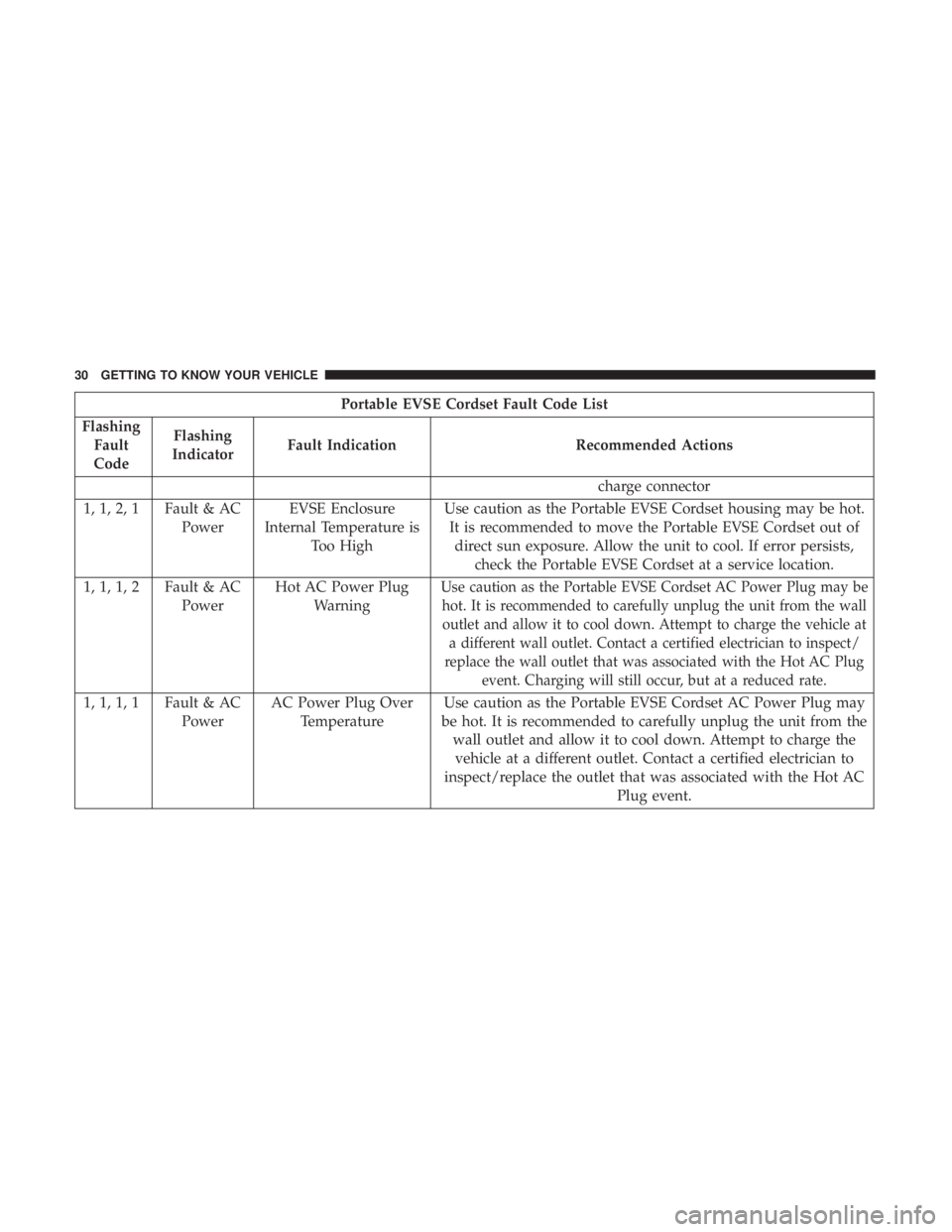
The fault code list in the table below provides a reference
for the important faults that are detected by the Portable
EVSE Cordset. When a fault is detected, the AC Power
Indicator, the Fault Indicator, or both the AC Power and
Fault Indicators will flash red. If only the AC Power
Indicator is red, there is a problem on the AC Power side of
the unit. If only the Fault Indicator is flashing red, there is
a problem internal to the unit or with the vehicle. If both
the AC Power and Fault Indicators are flashing red, an over
temperature condition is detected at either the AC plug or
within the EVSE enclosure. Additional information about
the faults is provided by a fault code that is displayed on
the two green Charge Rate Indicators. The fault code
consists of four digits, each with a value of 1 or 2. The value
of a digit is the number of indicators illuminated for that
part of the sequence. For example, fault code (1, 2, 1, 1) will
display the following sequence: One indicator will illumi-
nate for 0.3 seconds, then two indicators will illuminate,
3
GETTING TO KNOW YOUR VEHICLE 27
Page 31 of 614
Portable EVSE Cordset Fault Code List
Flashing Fault
Code Flashing
Indicator Fault Indication Recommended Actions
1, 1, 1, 1 Fault Portable EVSE Cordset Internal FaultUnplug the Portable EVSE Cordset from the vehicle charge inlet
and retry to charge. If the issue is not corrected, check the Por- table EVSE Cordset and Vehicle at a service location.
1, 1, 1, 2 Fault Portable EVSE Cordset Internal FaultUnplug the Portable EVSE Cordset from the vehicle charge inlet
and retry to charge. If the issue is not corrected, check the Por- table EVSE Cordset and Vehicle at a service location.
1, 2, 2, 1 AC Power Outlet Wiring Bad GroundAttempt to charge the vehicle at a different outlet. Contact a
certified electrician to check the electrical outlet and AC Supply (house wiring).
1, 2, 1, 1 Fault Portable EVSE Cordset Internal FaultCheck Portable EVSE Cordset and Vehicle at a service location.
1, 2, 1, 2 Fault CCID Leakage Current DetectedDisconnect charge connector and retry charging. If problem per-
sists, check the Portable EVSE Cordset and Vehicle at a service location.
2, 2, 2, 1 Fault Vehicle Interface Con- nectorError with the Vehicle Charge Connector Interface — Check for
water or other contamination in the vehicle charge inlet or charge connector.
2, 2, 2, 2 Fault Vehicle Interface Con- nectorError with the Vehicle Charge Connector Interface — Check for
water or other contamination in the vehicle charge inlet or
3
GETTING TO KNOW YOUR VEHICLE 29
Page 32 of 614
Portable EVSE Cordset Fault Code List
Flashing Fault
Code Flashing
Indicator Fault Indication Recommended Actions
charge connector
1, 1, 2, 1 Fault & AC Power EVSE Enclosure
Internal Temperature is Too High Use caution as the Portable EVSE Cordset housing may be hot.
It is recommended to move the Portable EVSE Cordset out of direct sun exposure. Allow the unit to cool. If error persists, check the Portable EVSE Cordset at a service location.
1, 1, 1, 2 Fault & AC PowerHot AC Power Plug
Warning
Use caution as the Portable EVSE Cordset AC Power Plug may behot. It is recommended to carefully unplug the unit from the walloutlet and allow it to cool down. Attempt to charge the vehicle at a different wall outlet. Contact a certified electrician to inspect/
replace the wall outlet that was associated with the Hot AC Plug event. Charging will still occur, but at a reduced rate.
1, 1, 1, 1 Fault & AC PowerAC Power Plug Over
Temperature Use caution as the Portable EVSE Cordset AC Power Plug may
be hot. It is recommended to carefully unplug the unit from the wall outlet and allow it to cool down. Attempt to charge thevehicle at a different outlet. Contact a certified electrician to
inspect/replace the outlet that was associated with the Hot AC Plug event.
30 GETTING TO KNOW YOUR VEHICLE
Page 33 of 614
FCC Notice:
This device complies with Part 15 of the FCC Rules and
with Industry Canada license-exempt RSS standard(s).
Operation is subject to the following two conditions:
1. This device may not cause harmful interference, and
2. This device must accept any interference received, in-cluding interference that may cause undesired opera-
tion.
NOTE: Changes or modifications not expressly approved
by the party responsible for compliance could void the
user ’s authority to operate the equipment.
This unit complies with ICES-003E of Industry Canada,
and EMC Directive 2004/108/EC.
Guidelines for preventing fire and electric shock:
• Ensure the charging cable is positioned so it will not be
stepped on, tripped over, or otherwise subjected to
damage or stress.
• There are no user serviceable parts inside.
• Do not use the charging cordset if it is visibly damaged.
Contact your authorized dealer for service. •
Do not place fingers, or any other objects inside the
charge connector.
• Do not allow children to operate this device. Adult
supervision is mandatory when children are in proxim-
ity when the charging cordset is in use.
NOTE: During normal operation, the charge connector or
AC plug may feel warm. If either one feels hot during
charging, unplug the charging cordset and have a qualified
electrician inspect the wall receptacle before you continue
charging.
WARNING!
Do not use the charging cordset with a receptacle that
is worn or damaged. Using the charging cordset with a
worn or damaged receptacle may cause burns or start a
fire.
AC Level 2 Charging (240V, 30 Amp)
AC Level 2 (240 V) charging requires a 240 V, Level 2 EVSE
(Charging station). A 30 A Level 2 EVSE for home instal-
lation is recommended.
When using public charging stations, ensure the charging
station is ready to provide charge and the vehicle is in
3
GETTING TO KNOW YOUR VEHICLE 31
Page 34 of 614
PARK before the charge connector is plugged into the
vehicle’s charge inlet. You will hear a “click” when the
charge connector is inserted correctly and is coupled with
the vehicle’s charge inlet. The vehicle should start charging
automatically. If not, please check the instructions at the
charging station.
NOTE:The vehicle should start charging automatically. If
not, please check the following:
• Charging Station – Check the indications and instruc-
tions at the charging station or
• Charging Schedule – Check whether the charging sched-
ule is enabled and if so, whether the vehicle is currently
within the scheduled charge time/day (weekday/
weekend). If the charging schedule is enabled within the
vehicle, you may override them for this charging event
by plugging in the charge connector, unplugging it, and
then plugging it back into the vehicle charge inlet.
Complete the double plug sequence within ten seconds
for it to override the set schedule.
To stop the charging process:
• Press the “STOP” button located on the front of the
EVSE station. •
Press the button on the charge connector first and then
remove the connector from the vehicle charge inlet.
• Plug the charge handle into the EVSE station and coil the
charging cord onto its holder. Do not leave the charging
cord laying on the ground.
Charging Times
The following factors determine the time it takes to charge
the high voltage battery:
• The high voltage battery’s current state of charge
• The type of EVSE used (Level 1 - 120V or Level 2 – 240V)
• Ambient temperature
• Whether the vehicle is ON during charging
NOTE:
• The charging times below are estimates based on charg-
ing a high voltage battery that has a 0% SOC value
displayed in the instrument cluster.
• Charging times will vary based on the age, condition,
state of charge, available current being provided to the
charger from its energy source, and temperature of the
high voltage battery.
32 GETTING TO KNOW YOUR VEHICLE
Page 35 of 614
•Charging times may be longer if a thermal self-protection
reduces the charging current from the EVSE.
• If the vehicle’s ignition is in either the ACC or RUN
position, the vehicle charge indicator may not indicate
greater than a 99% state of charge, and will continue to
charge the vehicle, due to the vehicle loads.
Type of EVSE Estimated Charge Time
Level 1 (120V/15A) Approximately 14 hours
Level 2 (240V/30A) Approximately 2 hours
Vehicle Charge Indicators
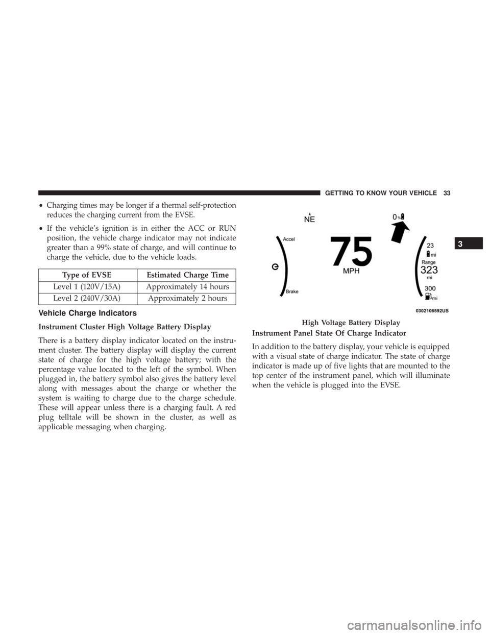
Instrument Cluster High Voltage Battery Display
There is a battery display indicator located on the instru-
ment cluster. The battery display will display the current
state of charge for the high voltage battery; with the
percentage value located to the left of the symbol. When
plugged in, the battery symbol also gives the battery level
along with messages about the charge or whether the
system is waiting to charge due to the charge schedule.
These will appear unless there is a charging fault. A red
plug telltale will be shown in the cluster, as well as
applicable messaging when charging. Instrument Panel State Of Charge Indicator
In addition to the battery display, your vehicle is equipped
with a visual state of charge indicator. The state of charge
indicator is made up of five lights that are mounted to the
top center of the instrument panel, which will illuminate
when the vehicle is plugged into the EVSE.High Voltage Battery Display
3
GETTING TO KNOW YOUR VEHICLE 33