Page 56 of 492

WARNING!
•A loose head restraint thrown forward in a collision
or hard stop could cause serious injury or death to
occupants of the vehicle. Always securely stow re-
moved head restraints in a location outside the
occupant compartment.
• ALL the head restraints MUST be reinstalled in the
vehicle to properly protect the occupants. Follow the
re-installation instructions above prior to operating
the vehicle or occupying a seat.
STEERING WHEEL
Manual Tilt/Telescoping Steering Column
This feature allows you to tilt the steering column upward
or downward. It also allows you to lengthen or shorten the
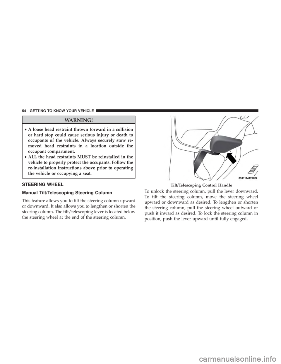
steering column. The tilt/telescoping lever is located below
the steering wheel at the end of the steering column. To unlock the steering column, pull the lever downward.
To tilt the steering column, move the steering wheel
upward or downward as desired. To lengthen or shorten
the steering column, pull the steering wheel outward or
push it inward as desired. To lock the steering column in
position, push the lever upward until fully engaged.
Tilt/Telescoping Control Handle
54 GETTING TO KNOW YOUR VEHICLE
Page 57 of 492

WARNING!
Do not adjust the steering column while driving.
Adjusting the steering column while driving or driv-
ing with the steering column unlocked, could cause the
driver to lose control of the vehicle. Failure to follow
this warning may result in serious injury or death.
Power Tilt/Telescoping Steering Column — If
Equipped
This feature allows you to tilt the steering column upward
or downward. It also allows you to lengthen or shorten the
steering column. The power tilt/telescoping steering col-
umn switch is located below the multifunction lever on the
steering column.To tilt the steering column, move the switch up or down as
desired. To lengthen or shorten the steering column, pull
the switch toward you or push the switch away from you
as desired.
NOTE:
For vehicles equipped with Driver Memory Seat,
you can use your remote keyless entry key fob or the
memory switch on the driver’s door trim panel to return
the tilt/telescopic steering column to pre-programmed
positions. Refer to “Driver Memory Seat” in this section.
Power Tilt/Telescoping Steering Switch
3
GETTING TO KNOW YOUR VEHICLE 55
Page 113 of 492

WARNING!
To avoid serious injury or death:
•Only devices designed for use in this type of outlet
should be inserted into any 12 Volt outlet.
• Do not touch with wet hands.
• Close the lid when not in use and while driving the
vehicle.
• If this outlet is mishandled, it may cause an electric
shock and failure.
CAUTION!
• Many accessories that can be plugged in draw power
from the vehicle’s battery even when not in use (i.e.,
cellular phones, etc.). Eventually, if plugged in long
enough, the vehicle’s battery will discharge suffi-
ciently to degrade battery life and/or prevent the
engine from starting.
• Accessories that draw higher power (i.e., coolers,
vacuum cleaners, lights, etc.) will degrade the battery
even more quickly. Only use these intermittently and
with greater caution.
• After the use of high power draw accessories or long
periods of the vehicle not being started (with acces-
sories still plugged in), the vehicle must be driven a
sufficient length of time to allow the alternator to
recharge the vehicle’s battery.
• Power outlets are designed for accessory plugs only.
Do not hang any type of accessory or accessory
bracket from the plug. Improper use of the power
outlet can cause damage.
3
GETTING TO KNOW YOUR VEHICLE 111
Page 152 of 492

AUXILIARY DRIVING SYSTEMS
Blind Spot Monitoring (BSM) — If Equipped
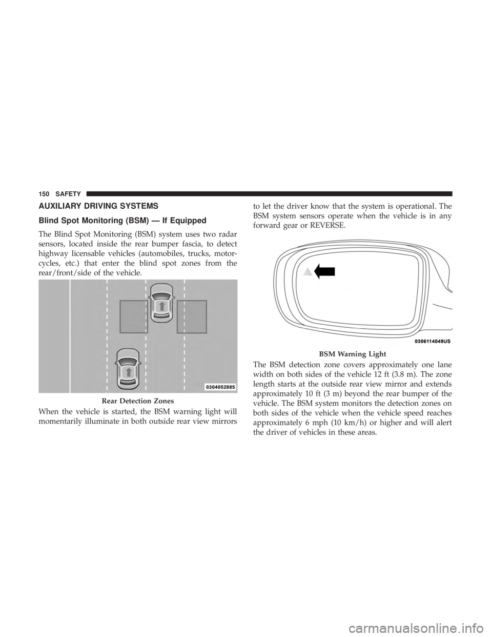
The Blind Spot Monitoring (BSM) system uses two radar
sensors, located inside the rear bumper fascia, to detect
highway licensable vehicles (automobiles, trucks, motor-
cycles, etc.) that enter the blind spot zones from the
rear/front/side of the vehicle.
When the vehicle is started, the BSM warning light will
momentarily illuminate in both outside rear view mirrorsto let the driver know that the system is operational. The
BSM system sensors operate when the vehicle is in any
forward gear or REVERSE.
The BSM detection zone covers approximately one lane
width on both sides of the vehicle 12 ft (3.8 m). The zone
length starts at the outside rear view mirror and extends
approximately 10 ft (3 m) beyond the rear bumper of the
vehicle. The BSM system monitors the detection zones on
both sides of the vehicle when the vehicle speed reaches
approximately 6 mph (10 km/h) or higher and will alert
the driver of vehicles in these areas.
Rear Detection Zones
BSM Warning Light
150 SAFETY
Page 428 of 492
Voice
After pressing the “Voice” button on the touchscreen, the
following settings will be available:
Setting NameSelectable Options
Voice Response Length Brief Detailed
Show Command List Neverw/Help Always
Clock
After pressing the “Clock” button on the touchscreen, the
following settings will be available:
Setting Name Selectable Options
Sync Time With GPS — If Equipped On
Off
NOTE:
The “Sync Time With GPS” feature will allow you to automatically have the radio set the time. Set Time Hours +–
Set Time Minutes +–
Time Format 12 hrs24 hrs
AM PM
426 MULTIMEDIA