2018 CHRYSLER 300 clock
[x] Cancel search: clockPage 64 of 492
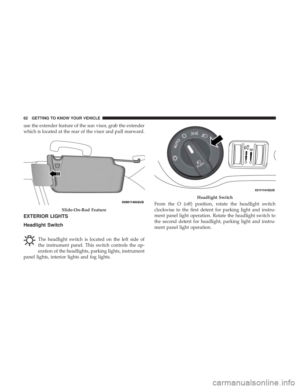
use the extender feature of the sun visor, grab the extender
which is located at the rear of the visor and pull rearward.
EXTERIOR LIGHTS
Headlight Switch
The headlight switch is located on the left side of
the instrument panel. This switch controls the op-
eration of the headlights, parking lights, instrument
panel lights, interior lights and fog lights. From the O (off) position, rotate the headlight switch
clockwise to the first detent for parking light and instru-
ment panel light operation. Rotate the headlight switch to
the second detent for headlight, parking light and instru-
ment panel light operation.
Slide-On-Rod Feature
Headlight Switch
62 GETTING TO KNOW YOUR VEHICLE
Page 66 of 492

NOTE:
•The Automatic High Beam Headlamp Control can be
turned on or off by selecting “ON” under “Auto High
Beam” within your Uconnect settings, as well as turning
the headlight switch to the AUTO position. Refer to
“Uconnect Settings” in “Multimedia” for further infor-
mation.
• Broken, muddy, or obstructed headlights and taillights
of vehicles in the field of view will cause headlights to
remain on longer (closer to the vehicle). Also, dirt, film,
and other obstructions on the windshield or camera lens
will cause the system to function improperly.
If the windshield is replaced, the camera must be re-aimed
to ensure proper performance. See your local authorized
dealer.
To Activate
1. Turn the headlight switch to the AUTO headlight posi- tion.
2. Push the multifunction lever away from you (toward front of vehicle) to engage the high beam mode.
NOTE: This system will not activate until the vehicle is at
or above 15 mph (24 km/h).
To Deactivate
1. Pull the multifunction lever toward you (or rearward in vehicle) to manually deactivate the system (normal
operation of low beams).
2. Push back on the multifunction lever to reactivate the system.
Flash-To-Pass
You can signal another vehicle with your headlights by
lightly pulling the multifunction lever toward you. This
will cause the high beam headlights to turn on, and remain
on, until the lever is released.
Automatic Headlights
This system automatically turns the headlights on or off
according to ambient light levels. To turn the system on,
rotate the headlight switch counterclockwise to the AUTO
position. When the system is on, the headlight time delay
feature is also on. This means the headlights will stay on
for up to 90 seconds after you place the ignition into the
OFF position. The headlight time delay can be pro-
grammed 0/30/60/90 seconds.
Refer to “Uconnect Settings” in “Multimedia” for further
information.
64 GETTING TO KNOW YOUR VEHICLE
Page 80 of 492
IconDescription
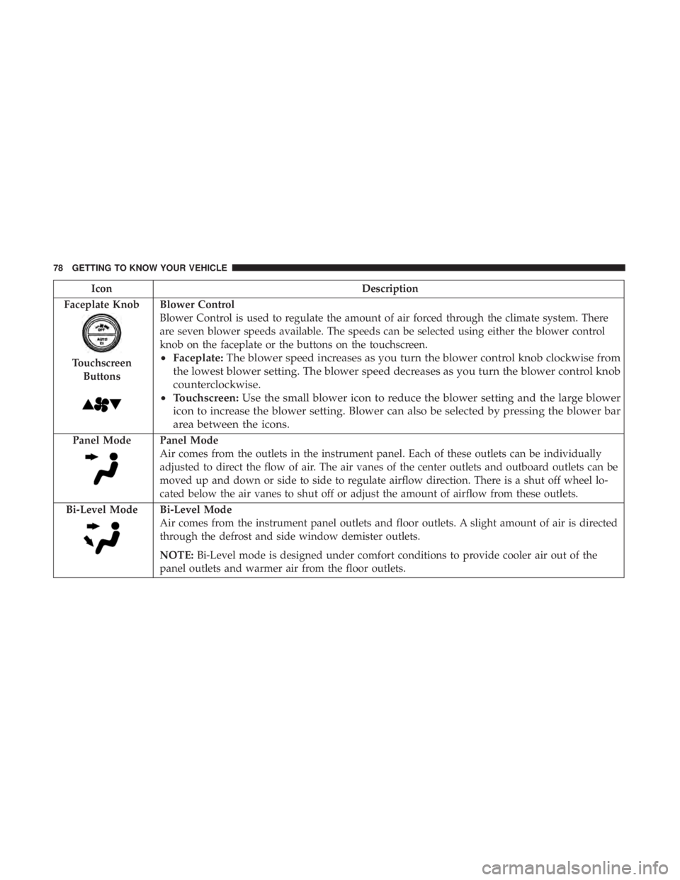
Faceplate Knob
Touchscreen Buttons
Blower Control
Blower Control is used to regulate the amount of air forced through the climate system. There
are seven blower speeds available. The speeds can be selected using either the blower control
knob on the faceplate or the buttons on the touchscreen.
• Faceplate: The blower speed increases as you turn the blower control knob clockwise from
the lowest blower setting. The blower speed decreases as you turn the blower control knob
counterclockwise.
• Touchscreen: Use the small blower icon to reduce the blower setting and the large blower
icon to increase the blower setting. Blower can also be selected by pressing the blower bar
area between the icons.
Panel ModePanel Mode
Air comes from the outlets in the instrument panel. Each of these outlets can be individually
adjusted to direct the flow of air. The air vanes of the center outlets and outboard outlets can be
moved up and down or side to side to regulate airflow direction. There is a shut off wheel lo-
cated below the air vanes to shut off or adjust the amount of airflow from these outlets.
Bi-Level Mode
Bi-Level Mode
Air comes from the instrument panel outlets and floor outlets. A slight amount of air is directed
through the defrost and side window demister outlets.
NOTE: Bi-Level mode is designed under comfort conditions to provide cooler air out of the
panel outlets and warmer air from the floor outlets.
78 GETTING TO KNOW YOUR VEHICLE
Page 233 of 492
CAUTION!
Towing the vehicle, coasting, or driving for any other
reason with the transmission in NEUTRAL can cause
severe transmission damage.
Refer to “Recreational Towing” in “Starting And Op-
erating” and “Towing A Disabled Vehicle” in “In Case
Of Emergency” for further information.
DRIVE (D)
This range should be used for most city and highway
driving. It provides the smoothest upshifts and downshifts,
and the best fuel economy. The transmission automatically
upshifts through all forward gears. The DRIVE position
provides optimum driving characteristics under all normal
operating conditions.
When frequent transmission shifting occurs (such as when
operating the vehicle under heavy loading conditions, in
hilly terrain, traveling into strong head winds, or while
towing a heavy trailer), use the AutoStick shift control (if
equipped, refer to “AutoStick” in this section for further
information) to select a lower gear. Under these conditions,
using a lower gear will improve performance and extend
transmission life by reducing excessive shifting and heat
buildup. During extremely cold temperatures (-22°F [-30°C] or be-
low), transmission operation may be modified depending
on engine and transmission temperature as well as vehicle
speed. Normal operation will resume once the transmis-
sion temperature has risen to a suitable level.
SPORT (S) — If Equipped
This mode alters the transmission’s automatic shift sched-
ule for sportier driving. Upshift speeds are increased to
make full use of available engine power.
To access SPORT mode, push down on the gear selector
and rotate it fully clockwise, or push the SPORT button in
the center stack.
LOW (L) — If Equipped
Use this range for engine braking when descending very
steep grades. In this range, the transmission will downshift
for increased engine braking. To access the LOW position,
push down on the gear selector and rotate it fully clock-
wise.
Transmission Limp Home Mode
Transmission function is monitored electronically for ab-
normal conditions. If a condition is detected that could
result in transmission damage, Transmission Limp Home
6
STARTING AND OPERATING 231
Page 309 of 492
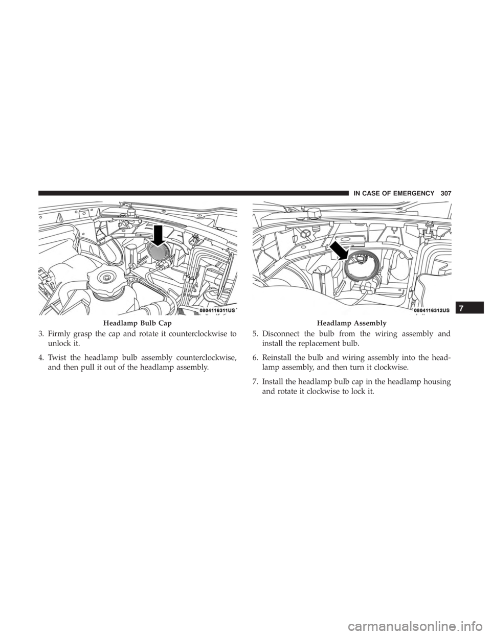
3. Firmly grasp the cap and rotate it counterclockwise tounlock it.
4. Twist the headlamp bulb assembly counterclockwise, and then pull it out of the headlamp assembly. 5. Disconnect the bulb from the wiring assembly and
install the replacement bulb.
6. Reinstall the bulb and wiring assembly into the head- lamp assembly, and then turn it clockwise.
7. Install the headlamp bulb cap in the headlamp housing and rotate it clockwise to lock it.
Headlamp Bulb CapHeadlamp Assembly
7
IN CASE OF EMERGENCY 307
Page 310 of 492

CAUTION!
Do not touch the new bulb with your fingers. Oil
contamination will severely shorten bulb life. If the
bulb comes in contact with any oily surface, clean the
bulb with rubbing alcohol.
Front Turn Signal Lamps
1. Open the hood.
NOTE:Removal of the air cleaner filter housing may be
necessary prior to replacing bulbs in the headlamp assem-
bly on the driver side of the vehicle. 2. Reach behind the headlamp housing to access the turn
signal (inboard) bulb cap.
3. Firmly grasp the cap and rotate it counterclockwise to unlock it.
4. Squeeze the two tabs on the side of the bulb socket and pull straight out from the lamp assembly.
5. Disconnect the bulb from the wiring connector and install the replacement bulb.
6. Install the bulb and connector assembly straight into the lamp until it locks in place.
Headlamp Assembly Location
Headlamp Assembly
308 IN CASE OF EMERGENCY
Page 311 of 492

7. Install the turn signal bulb cap in the headlamp housingand rotate clockwise to lock in place.
Front Fog Lamp
The Front Fog Lamps use LED sources that are not
serviceable separately. The Front Fog Lamp must be re-
placed as an assembly; see your authorized dealer.
Front/Rear Side Marker Lamp
The Side Markers use LED lamps that are not serviceable
separately. The Side Markers must be replaced as an
assembly, see your authorized dealer.
Rear Backup Lamp And Turn Signal Lamps
The Rear Backup and Turn Signal Lamp use LED sources
that are not serviceable separately. The Rear Lamps must
be replaced as an assembly, please see your authorized
dealer.
License Lamp
The License Lamp uses an LED source that is not service-
able separately. The License Lamp must be replaced as an
assembly; see your authorized dealer.
Center High Mounted Stop Lamp (CHMSL)
The CHMSL Lamp uses LED sources that are not service-
able separately. The CHMSL Lamp must be replaced as an
assembly; see your authorized dealer.
FUSES
WARNING!
•When replacing a blown fuse, always use an appro-
priate replacement fuse with the same amp rating as
the original fuse. Never replace a fuse with another
fuse of higher amp rating. Never replace a blown
fuse with metal wires or any other material. Do not
place a fuse inside a circuit breaker cavity or vice
versa. Failure to use proper fuses may result in
serious personal injury, fire and/or property damage.
• Before replacing a fuse, make sure that the ignition is
off and that all the other services are switched off
and/or disengaged.
• If the replaced fuse blows again, contact an autho-
rized dealer.
(Continued)
7
IN CASE OF EMERGENCY 309
Page 320 of 492
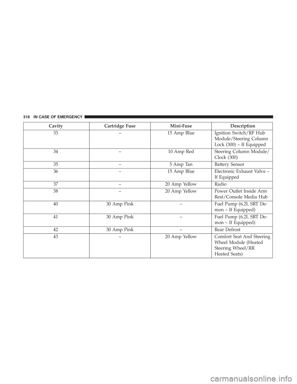
CavityCartridge Fuse Mini-FuseDescription
33 –15 Amp Blue Ignition Switch/RF Hub
Module/Steering Column
Lock (300) – If Equipped
34 –10 Amp Red Steering Column Module/
Clock (300)
35 –5 Amp Tan Battery Sensor
36 –15 Amp Blue Electronic Exhaust Valve –
If Equipped
37 –20 Amp Yellow Radio
38 –20 Amp Yellow Power Outlet Inside Arm
Rest/Console Media Hub
40 30 Amp Pink –Fuel Pump (6.2L SRT De-
mon – If Equipped)
41 30 Amp Pink –Fuel Pump (6.2L SRT De-
mon – If Equipped)
42 30 Amp Pink –Rear Defrost
43 –20 Amp Yellow Comfort Seat And Steering
Wheel Module (Heated
Steering Wheel/RR
Heated Seats)
318 IN CASE OF EMERGENCY