2018 CHRYSLER 300 check engine light
[x] Cancel search: check engine lightPage 191 of 492

Your vehicle may also be designed to perform any of these
other functions in response to the Enhanced Accident
Response System:
•Turn off the Fuel Filter Heater, Turn off the HVAC
Blower Motor, Close the HVAC Circulation Door
• Cut off battery power to the:
• Engine
• Electric Motor (if equipped)
• Electric power steering
• Brake booster
• Electric park brake
• Automatic transmission gear selector
• Horn
• Front wiper
• Headlamp washer pump NOTE:
After an accident, remember to cycle the ignition to
the STOP (OFF/LOCK) position and remove the key from
the ignition switch to avoid draining the battery. Carefully
check the vehicle for fuel leaks in the engine compartment
and on the ground near the engine compartment and fuel
tank before resetting the system and starting the engine. If
there are no fuel leaks or damage to the vehicle electrical
devices (e.g. headlights) after an accident, reset the system
by following the procedure described below.
Enhanced Accident Response System Reset
Procedure
In order to reset the Enhanced Accident Response System
functions after an event, the ignition switch must be
changed from ignition START or ON/RUN to ignition OFF.
Carefully check the vehicle for fuel leaks in the engine
compartment and on the ground near the engine compart-
ment and fuel tank before resetting the system and starting
the engine.
5
SAFETY 189
Page 213 of 492

WARNING!
An improperly attached, damaged, folded, or stacked
floor mat, or damaged floor mat fasteners may cause
your floor mat to interfere with the accelerator, brake,
or clutch pedals and cause a loss of vehicle control. To
prevent SERIOUS INJURY or DEATH:
•ALWAYS securely attach
your floor mat using the
floor mat fasteners. DO NOT install your floor mat
upside down or turn your floor mat over. Lightly pull
to confirm mat is secured using the floor mat fasten-
ers on a regular basis.
• ALWAYS REMOVE THE EXISTING FLOOR MAT
FROM THE VEHICLE
before installing any other
floor mat. NEVER install or stack an additional floor
mat on top of an existing floor mat.
• ONLY install floor mats designed to fit your vehicle.
NEVER install a floor mat that cannot be properly
attached and secured to your vehicle. If a floor mat
needs to be replaced, only use a FCA approved floor
mat for the specific make, model, and year of your
vehicle.
• ONLY use the driver ’s side floor mat on the driver ’s
side floor area. To check for interference, with the
(Continued)
WARNING! (Continued)
vehicle properly parked with the engine off, fully
depress the accelerator, the brake, and the clutch
pedal (if present) to check for interference. If your
floor mat interferes with the operation of any pedal,
or is not secure to the floor, remove the floor mat
from the vehicle and place the floor mat in your
trunk.
• ONLY use the passenger ’s side floor mat on the
passenger ’s side floor area.
• ALWAYS make sure objects cannot fall or slide into
the driver ’s side floor area when the vehicle is
moving. Objects can become trapped under accelera-
tor, brake, or clutch pedals and could cause a loss of
vehicle control.
• NEVER place any objects under the floor mat (e.g.,
towels, keys, etc.). These objects could change the
position of the floor mat and may cause interference
with the accelerator, brake, or clutch pedals.
• If the vehicle carpet has been removed and re-
installed, always properly attach carpet to the floor
and check the floor mat fasteners are secure to the
vehicle carpet. Fully depress each pedal to check for
(Continued)
5
SAFETY 211
Page 224 of 492

NOTE:A new engine may consume some oil during its
first few thousand miles (kilometers) of operation. This
should be considered a normal part of the break-in and not
interpreted as an indication of difficulty. Please check your
oil level with the engine oil indicator often during the
break in period. Add oil as required.
PARKING BRAKE
Before leaving the vehicle, make sure that the parking
brake is fully applied and place the gear selector in the
PARK position.
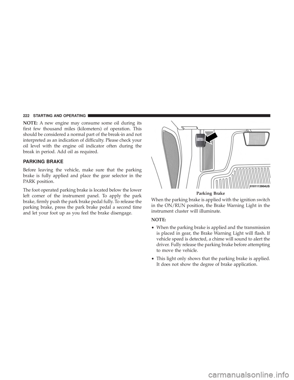
The foot operated parking brake is located below the lower
left corner of the instrument panel. To apply the park
brake, firmly push the park brake pedal fully. To release the
parking brake, press the park brake pedal a second time
and let your foot up as you feel the brake disengage. When the parking brake is applied with the ignition switch
in the ON/RUN position, the Brake Warning Light in the
instrument cluster will illuminate.
NOTE:
•
When the parking brake is applied and the transmission
is placed in gear, the Brake Warning Light will flash. If
vehicle speed is detected, a chime will sound to alert the
driver. Fully release the parking brake before attempting
to move the vehicle.
• This light only shows that the parking brake is applied.
It does not show the degree of brake application.
Parking Brake
222 STARTING AND OPERATING
Page 343 of 492

SCHEDULED SERVICING
Your vehicle is equipped with an automatic oil change
indicator system. The oil change indicator system will
remind you that it is time to take your vehicle in for
scheduled maintenance.
Based on engine operation conditions, the oil change
indicator message will illuminate. This means that service
is required for your vehicle. Operating conditions such as
frequent short-trips, trailer tow, extremely hot or cold
ambient temperatures, and E85 fuel usage will influence
when the “Change Oil” or “Oil Change Required” message
is displayed. Severe Operating Conditions can cause the
change oil message to illuminate as early as 3,500 miles
(5,600 km) since last reset. Have your vehicle serviced as
soon as possible, within the next 500 miles (805 km).
The “Oil Change Required” message will be displayed in
the instrument cluster and a single chime will sound,
indicating that an oil change is necessary.
Your authorized dealer will reset the oil change indicator
message after completing the scheduled oil change. If a
scheduled oil change is performed by someone other than
your authorized dealer, the message can be reset by
referring to “Instrument Cluster Display” in “Getting To
Know Your Instrument Panel” for further information.NOTE:
Under no circumstances should oil change inter-
vals exceed 10,000 miles (16,000 km), twelve months or 350
hours of engine run time, whichever comes first. The 350
hours of engine run or idle time is generally only a concern
for fleet customers.
Severe Duty All Models
Change Engine Oil at 4,000 miles (6,500 km) or 350 hours of
engine run time if the vehicle is operated in a dusty and
off-road environment, or is operated predominantly at idle
or only very low engine RPM’s. This type of vehicle use is
considered Severe Duty.
Once A Month Or Before A Long Trip:
• Check engine oil level.
• Check windshield washer fluid level.
• Check tire pressure and look for unusual wear or
damage. Rotate tires at the first sign of irregular wear,
even if it occurs before your next scheduled service.
• Check the fluid levels of the coolant reservoir, brake
master cylinder, and power steering (if equipped) and
fill as needed.
• Check function of all interior and exterior lights.
8
SERVICING AND MAINTENANCE 341
Page 369 of 492

•Maintain engine coolant (antifreeze) concentration at a
minimum of 50% OAT coolant (conforming to
MS.90032) and distilled water for proper corrosion pro-
tection of your engine which contains aluminum com-
ponents.
• Make sure that the coolant expansion bottle overflow
hoses are not kinked or obstructed.
• Keep the front of the radiator clean. If your vehicle is
equipped with air conditioning, keep the front of the
condenser clean.
• Do not change the thermostat for Summer or Winter
operation. If replacement is ever necessary, install ONLY
the correct type thermostat. Other designs may result in
unsatisfactory engine coolant (antifreeze) performance,
poor gas mileage, and increased emissions.
Brake System
In order to assure brake system performance, all brake
system components should be inspected periodically. Refer
to the “Maintenance Plan” in this section for the proper
maintenance intervals.
WARNING!
Riding the brakes can lead to brake failure and possi-
bly a collision. Driving with your foot resting or riding
on the brake pedal can result in abnormally high brake
temperatures, excessive lining wear, and possible
brake damage. You would not have your full braking
capacity in an emergency.
Fluid Level Check — Brake Master Cylinder
Check the fluid level in the master cylinder immediately if
the brake system warning light indicates system failure.
Check the fluid level in the master cylinder when perform-
ing underhood services.
Clean the top of the master cylinder area before removing
the cap. Add fluid to bring the level up to the top of the
“FULL” mark on the side of the master cylinder reservoir.
Overfilling of fluid is not recommended because it may
cause leaking in the system.
8
SERVICING AND MAINTENANCE 367
Page 407 of 492

Tighten the lug nuts/bolts in a star pattern until each
nut/bolt has been tightened twice. Ensure that the socket is
fully engaged on the lug nut/bolt (do not insert it half-
way).
NOTE:If in doubt about the correct tightness, have them
checked with a torque wrench by your authorized dealer or
service station.
After 25 miles (40 km), check the lug nut/bolt torque to be
sure that all the lug nuts/bolts are properly seated against
the wheel.WARNING!
To avoid the risk of forcing the vehicle off the jack, do
not tighten the lug nuts fully until the vehicle has been
lowered. Failure to follow this warning may result in
personal injury.
FUEL REQUIREMENTS
3.6L Engine
This engine is designed to meet all emis-
sions regulations and provide excellent
fuel economy and performance when
using high-quality unleaded “Regular”
gasoline having an octane rating of 87 as
specified by the (R+M)/2 method. The
use of higher octane “Premium” gaso-
line will not provide any benefit over “Regular” gasoline in
these engines.
While operating on gasoline with an octane number of 87,
hearing a light knocking sound from the engine is not a
cause for concern. However, if the engine is heard making
a heavy knocking sound, see your dealer immediately. Use
Torque Patterns
9
TECHNICAL SPECIFICATIONS 405
Page 424 of 492

CAUTION!
Do NOT attach any object to the touchscreen, doing so
can result in damage to the touchscreen.
Customer Programmable Features — Uconnect
4C/4C NAV Settings
Press the “Apps” button (If Equipped), and then
press the “Settings” button on the touchscreen to dis-
play the menu setting screen. In this mode, the
Uconnect system allows you to access programmable
features that may be equipped such as Language, Dis-
play, Units, Voice, Clock, Safety & Driving Assistance,
Lights, Doors & Locks, Auto-On Comfort, Engine Off
Options, Audio, Phone, SiriusXM Setup, Restore Set-
tings, Clear Personal Data and System Information.
NOTE: Depending on the vehicles options, feature settings
may vary.
When making a selection, press the button on the touch-
screen to enter the desired mode. Once in the desired
mode, press and release the preferred setting “option” until
a check-mark appears next to the setting, showing that
setting has been selected. Once the setting is complete,
either press the back arrow button on the touchscreen to
return to the previous menu, or press the “X” button on the
touchscreen to close out of the settings screen. Pressing the
up or down arrow button on the right side of the screen
will allow you to toggle up or down through the available
settings.
Uconnect 4C/4C NAV Buttons On The Touchscreen And
Buttons On The Faceplate
1 — Uconnect Buttons On The Touchscreen
2 — Uconnect Buttons On The Faceplate 422 MULTIMEDIA
Page 476 of 492

Brightness, Interior Lights.....................70
Bulb Replacement ......................... .304
Bulbs, Light .......................... .212, 304
Camera, Rear ............................ .277
Capacities, Fluid .......................... .412
Caps, Filler Oil (Engine) ........................ .346, 352
Radiator (Coolant Pressure) .................365
Carbon Monoxide Warning ................209, 409
Cargo Vehicle Loading ......................... .281
Cargo Area Cover ...........................93
Cargo Compartment .........................93
Car Washes .............................. .397
Cellular Phone ........................... .447
Certification Label ......................... .281
Chains, Tire ............................. .392
Changing A Flat Tire ....................... .371
Chart, Tire Sizing .......................... .373
Check Engine Light (Malfunction Indicator Light). . . .137
Checking Your Vehicle For Safety ...............208
Checks, Safety ............................ .208
Child Restraint ........................... .191Child Restraints
Booster Seats ........................... .195
Child Seat Installation .....................205
How To Stow An unused ALR Seat Belt ........202
Infant And Child Restraints .................193
Lower Anchors And Tethers For Children .......197
Older Children And Child Restraints ...........194
Seating Positions ........................ .196
Child Safety Locks ..........................39
Clean Air Gasoline ........................ .406
Cleaning Wheels ............................... .391
Climate Control ............................75
Automatic ..............................75
Coin Holder ............................. .103
Cold Weather Operation ..................... .220
Compact
Disc (CD) Maintenance ................464
Compact Spare Tire ........................ .389
Console, Floor ............................ .103
Contract, Service .......................... .468
Cooling Pressure Cap (Radiator Cap) ............365
Cooling System ........................... .362
Adding Coolant (Antifreeze) .................364
Coolant Capacity ........................ .412
Coolant Level ....................... .363, 366
474 INDEX