Page 294 of 492

AutoStick — If Equipped
•When using the AutoStick shift control, select the high-
est gear that allows for adequate performance and
avoids frequent downshifts. For example, choose “5” if
the desired speed can be maintained. Choose “4” or “3”
if needed to maintain the desired speed.
• To prevent excess heat generation, avoid continuous
driving at high RPM. Reduce vehicle speed as necessary
to avoid extended driving at high RPM. Return to a
higher gear or vehicle speed when grade and road
conditions allow.
Cooling System
To reduce potential for engine and transmission overheat-
ing, take the following actions:
City Driving
• In city traffic — while stopped, place the transmission in
NEUTRAL, but do not increase engine idle speed.
Highway Driving
• Reduce speed.
• Temporarily turn off air conditioning.
RECREATIONAL TOWING (BEHIND MOTORHOME,
ETC.)
Recreational towing (with all four wheels on the ground, or
using a tow dolly) is NOT ALLOWED. The only accept-
able method for towing this vehicle (behind another ve-
hicle) is on a vehicle trailer with all four wheels OFFthe
ground.
CAUTION!
Towing this vehicle in violation of the above require-
ments can cause severe transmission and/or transfer
case damage. Damage from improper towing is not
covered under the New Vehicle Limited Warranty.
DRIVING TIPS
Driving On Slippery Surfaces
Information in this section will aid in safe controlled
launches in adverse conditions.
292 STARTING AND OPERATING
Page 297 of 492
CAUTION!(Continued)
•Do not exceed 5 mph (8 km/h) when driving through
standing water. This will minimize wave effects.
• Driving through standing water may cause damage
to your vehicle’s drivetrain components. Always in-
spect your vehicle’s fluids (i.e., engine oil, transmis-
sion, axle, etc.) for signs of contamination (i.e., fluid
that is milky or foamy in appearance) after driving
through standing water. Do not continue to operate
the vehicle if any fluid appears contaminated, as this
may result in further damage. Such damage is not
covered by the New Vehicle Limited Warranty.
• Getting water inside your vehicle’s engine can cause
it to lock up and stall out, and cause serious internal
damage to the engine. Such damage is not covered by
the New Vehicle Limited Warranty.
6
STARTING AND OPERATING 295
Page 299 of 492

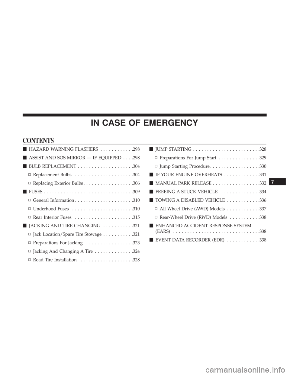
IN CASE OF EMERGENCY
CONTENTS
�HAZARD WARNING FLASHERS ............298
� ASSIST AND SOS MIRROR — IF EQUIPPED . . . .298
� BULB REPLACEMENT ....................304
▫ Replacement Bulbs .....................304
▫ Replacing Exterior Bulbs ..................306
� FUSES ............................... .309
▫ General Information .....................310
▫ Underhood Fuses ..................... .310
▫ Rear Interior Fuses .....................315
� JACKING AND TIRE CHANGING ...........321
▫ Jack Location/Spare Tire Stowage ...........321
▫ Preparations For Jacking .................323
▫ Jacking And Changing A Tire ..............324
▫ Road Tire Installation ...................328 �
JUMP STARTING ....................... .328
▫ Preparations For Jump Start ...............329
▫ Jump Starting Procedure ..................330
� IF YOUR ENGINE OVERHEATS .............331
� MANUAL PARK RELEASE .................332
� FREEING A STUCK VEHICLE ..............334
� TOWING A DISABLED VEHICLE ............336
▫ All Wheel Drive (AWD) Models ............337
▫ Rear-Wheel Drive (RWD) Models ...........338
� ENHANCED ACCIDENT RESPONSE SYSTEM
(EARS) .............................. .338
� EVENT DATA RECORDER (EDR) ............338
7
Page 312 of 492
WARNING!(Continued)
•If a general protection fuse for safety systems (air
bag system, braking system), power unit systems
(engine system, transmission system) or steering
system blows, contact an authorized dealer.
General Information
The fuses protect electrical systems against excessive cur-
rent.
When a device does not work, you must check the fuse
element inside the blade fuse for a break/melt.
Also, please be aware that when using power outlets for
extended periods of time with the engine off may result in
vehicle battery discharge.
Underhood Fuses
The Front Power Distribution Center is located in the
engine compartment. This module contains fuses and
relays. Fuse cavity location and descriptions are printed on
the inside of the power distribution center cover.
Blade Fuses
1 — Fuse Element
2 — Blade Fuse with a good/functional fuse element.
3 — Blade fuse with a NOT functional / BAD fuse element (blown
fuse).
310 IN CASE OF EMERGENCY
Page 315 of 492
CavityCartridge Fuse Mini-Fuse Description
22 40 Amp Green /
20 Amp Blue – Po- lice –
Engine Cooling Pump (6.2L Super-
charged) / Police Bat Feed # 3
23 20 Amp Blue –Police Bat Feed # 1
24 50 Amp Red / 20
Amp Blue –
Radiator Fan (6.2L Supercharged) / Police
Ignition Run/ACC Feed # 3
28 –– Fuse – Spare
29 –15 Amp Blue Transmission Control Module
(Challenger/Charger Police) / Electronic Shift Module (Challenger)
30 –– Fuse – Spare
31 –25 Amp Clear Engine Module
32 –– Fuse – Spare
33 –– Fuse – Spare
34 –25 Amp Clear Powertrain #1
35 –20 Amp Yellow Powertrain #2
36 –10 Amp Red Anti-Lock Brake Module
37 –10 Amp Red Engine Controller / Rad Fan Relays
(Charger/300) / Electric Power SteeringModule (Charger/300) / 5-Speed TCM
38 –10 Amp Red Airbag Module
7
IN CASE OF EMERGENCY 313
Page 323 of 492

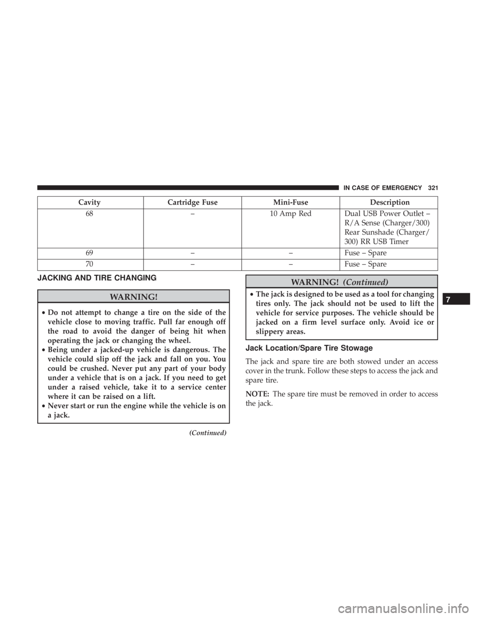
CavityCartridge Fuse Mini-FuseDescription
68 –10 Amp Red Dual USB Power Outlet –
R/A Sense (Charger/300)
Rear Sunshade (Charger/
300) RR USB Timer
69 ––Fuse – Spare
70 ––Fuse – Spare
JACKING AND TIRE CHANGING
WARNING!
•Do not attempt to change a tire on the side of the
vehicle close to moving traffic. Pull far enough off
the road to avoid the danger of being hit when
operating the jack or changing the wheel.
• Being under a jacked-up vehicle is dangerous. The
vehicle could slip off the jack and fall on you. You
could be crushed. Never put any part of your body
under a vehicle that is on a jack. If you need to get
under a raised vehicle, take it to a service center
where it can be raised on a lift.
• Never start or run the engine while the vehicle is on
a jack.
(Continued)
WARNING! (Continued)
•The jack is designed to be used as a tool for changing
tires only. The jack should not be used to lift the
vehicle for service purposes. The vehicle should be
jacked on a firm level surface only. Avoid ice or
slippery areas.
Jack Location/Spare Tire Stowage
The jack and spare tire are both stowed under an access
cover in the trunk. Follow these steps to access the jack and
spare tire.
NOTE: The spare tire must be removed in order to access
the jack.
7
IN CASE OF EMERGENCY 321
Page 331 of 492

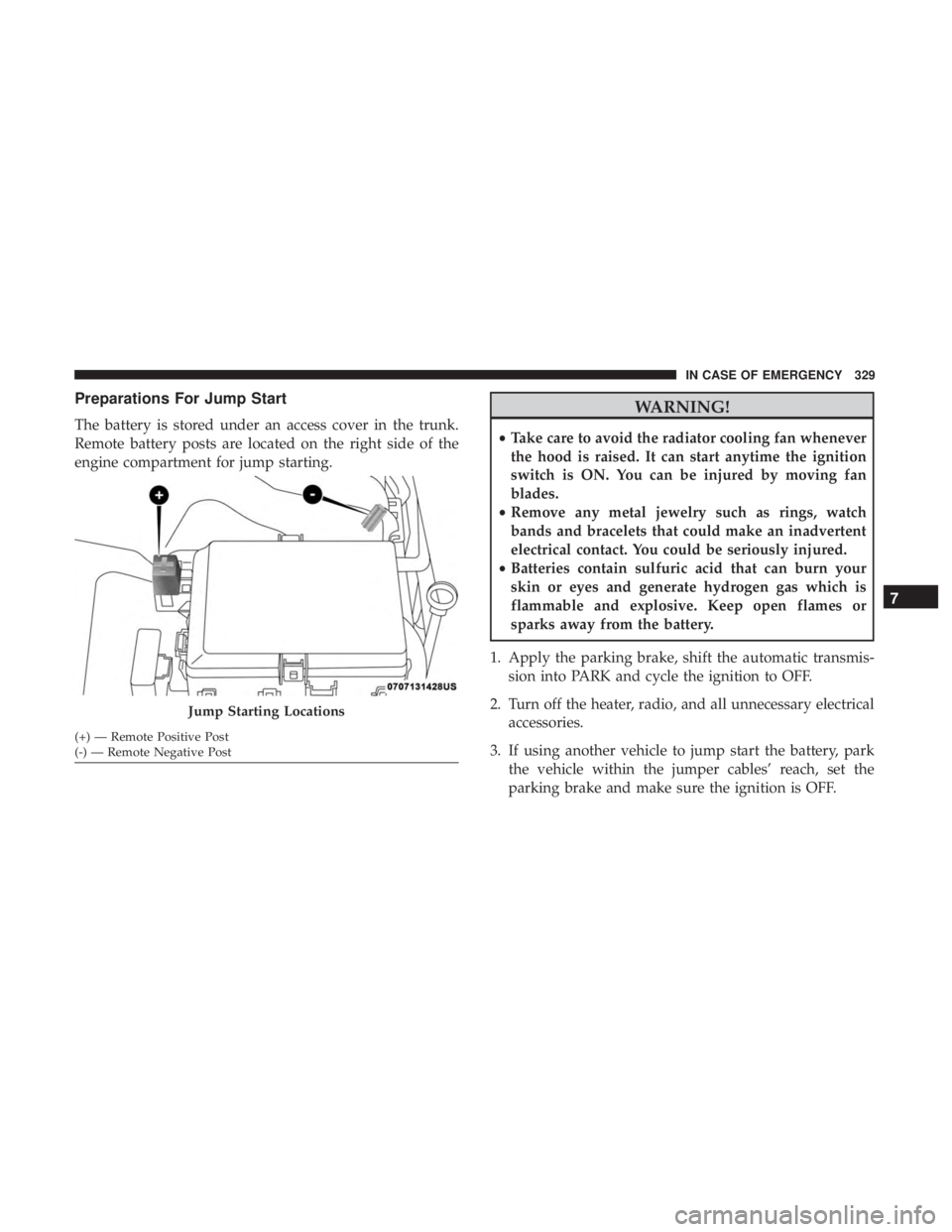
Preparations For Jump Start
The battery is stored under an access cover in the trunk.
Remote battery posts are located on the right side of the
engine compartment for jump starting.
WARNING!
•Take care to avoid the radiator cooling fan whenever
the hood is raised. It can start anytime the ignition
switch is ON. You can be injured by moving fan
blades.
• Remove any metal jewelry such as rings, watch
bands and bracelets that could make an inadvertent
electrical contact. You could be seriously injured.
• Batteries contain sulfuric acid that can burn your
skin or eyes and generate hydrogen gas which is
flammable and explosive. Keep open flames or
sparks away from the battery.
1. Apply the parking brake, shift the automatic transmis- sion into PARK and cycle the ignition to OFF.
2. Turn off the heater, radio, and all unnecessary electrical accessories.
3. If using another vehicle to jump start the battery, park the vehicle within the jumper cables’ reach, set the
parking brake and make sure the ignition is OFF.
Jump Starting Locations
(+) — Remote Positive Post
(-) — Remote Negative Post
7
IN CASE OF EMERGENCY 329
Page 332 of 492

WARNING!
Do not allow vehicles to touch each other as this could
establish a ground connection and personal injury
could result.
Jump Starting Procedure
WARNING!
Failure to follow this jump starting procedure could
result in personal injury or property damage due to
battery explosion.
CAUTION!
Failure to follow these procedures could result in
damage to the charging system of the booster vehicle
or the discharged vehicle.
NOTE: Make sure at all times that unused ends of jumper
cables are not contacting each other or either vehicle while
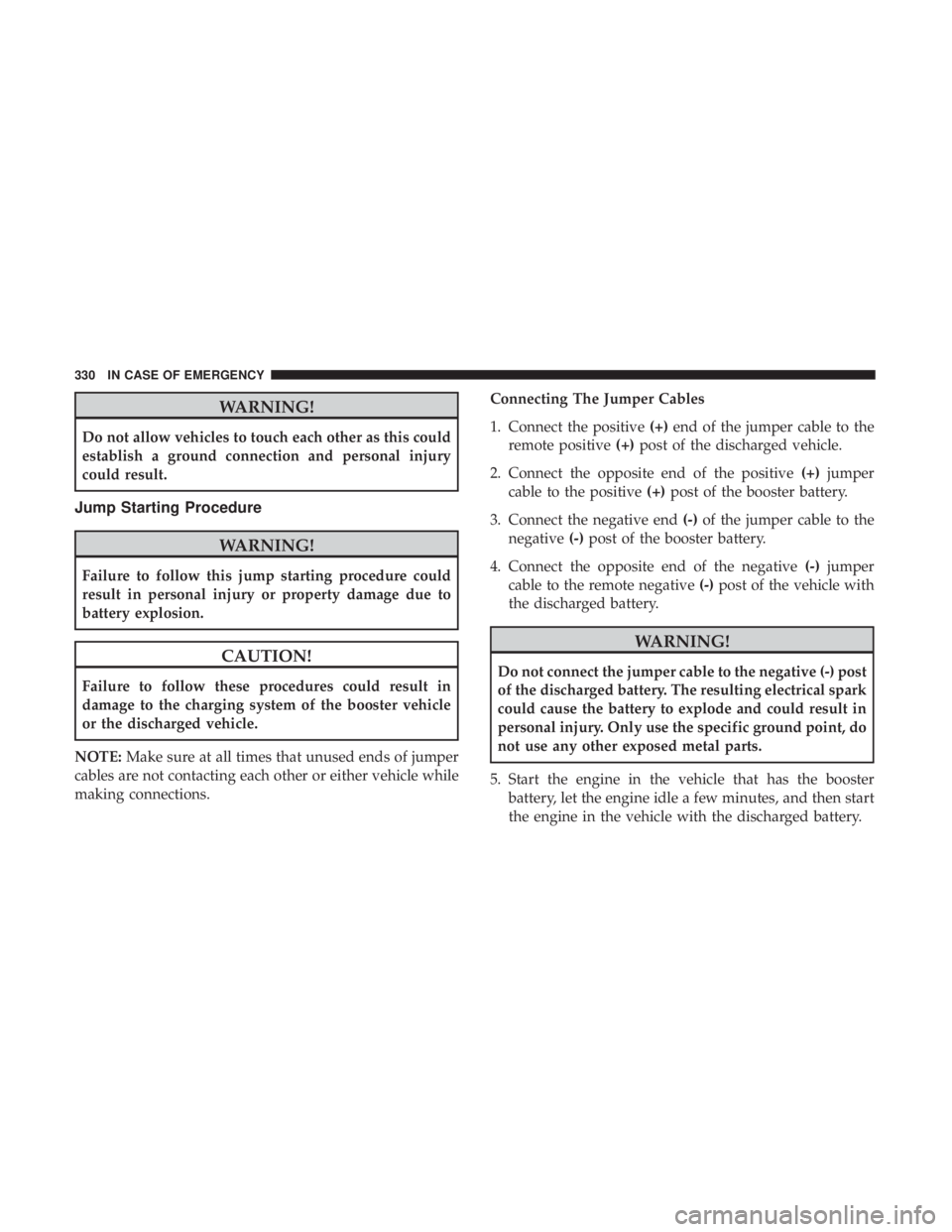
making connections. Connecting The Jumper Cables
1. Connect the positive
(+)end of the jumper cable to the
remote positive (+)post of the discharged vehicle.
2. Connect the opposite end of the positive (+)jumper
cable to the positive (+)post of the booster battery.
3. Connect the negative end (-)of the jumper cable to the
negative (-)post of the booster battery.
4. Connect the opposite end of the negative (-)jumper
cable to the remote negative (-)post of the vehicle with
the discharged battery.
WARNING!
Do not connect the jumper cable to the negative (-) post
of the discharged battery. The resulting electrical spark
could cause the battery to explode and could result in
personal injury. Only use the specific ground point, do
not use any other exposed metal parts.
5. Start the engine in the vehicle that has the booster battery, let the engine idle a few minutes, and then start
the engine in the vehicle with the discharged battery.
330 IN CASE OF EMERGENCY