2018 Alfa Romeo Stelvio seat adjustment
[x] Cancel search: seat adjustmentPage 31 of 276
Sparco Racing Seats — If Equipped
Forward/Rearward Adjustment
The adjustment lever is at the front of the
seat, near the floor. Pull the lever upward
to move the seat forward or rearward.
Release the lever once the seat is in the
desired position. Using body pressure,
move forward and rearward on the seat
to be sure that the seat adjusters have
latched.
Height Adjustment
Pull upward on the height adjustment
lever to raise the seat height, or push
downward on the lever to lower the seat
height.Seatback Recline
To adjust the seatback, lift the recline
lever located on the outboard side of the
seat, lean back to the desired position
and release the lever. To return the
seatback, lift the lever, lean forward and
release the lever.
Power Front Seats
The power seat switch is located on the
outboard side of the seat near the floor.
Use this switch to move the driver's seat
up, down, forward, and rearward, or to
recline the seatback.
Caution!
Do not place any article under a power seat
or impede its ability to move as it may cause
damage to the seat controls. Seat travel
may become limited if movement is stopped
by an obstruction in the seat's path.
Forward/Rearward Adjustment
Push the seat switch forward or rearward
to adjust to your desired position.
Seatback Recline
The angle of the seatback can be
adjusted forward or rearward. Push the
seatback switch forward or rearward,
and the seat will move in the direction of
the switch. Release the switch when the
desired position is reached.
Power Lumbar — If Equipped
Vehicles equipped with power driver or
passenger seats may also be equipped
with power lumbar. The power lumbar
switch is located on the outboard side of
the power seat. Push the switch forward
or rearward to increase or decrease the
lumbar support. Push the switch upward
or downward to raise or lower the lumbar
support.
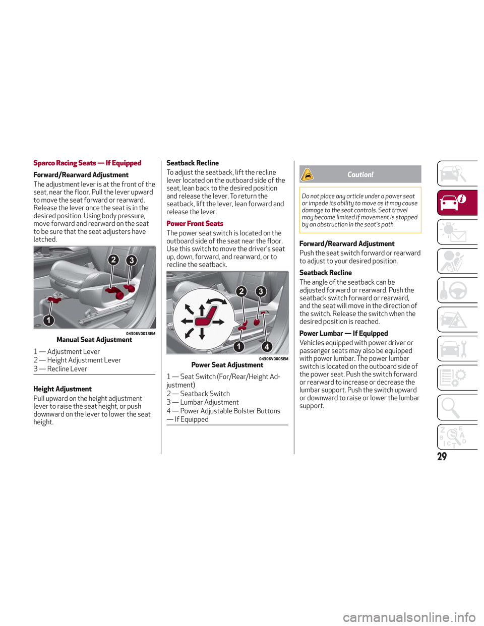
04306V0013EMManual Seat Adjustment
1 — Adjustment Lever
2 — Height Adjustment Lever
3 — Recline Lever04306V0005EMPower Seat Adjustment
1 — Seat Switch (For/Rear/Height Ad-
justment)
2 — Seatback Switch
3 — Lumbar Adjustment
4 — Power Adjustable Bolster Buttons
— If Equipped
29
Page 32 of 276

Height Adjustment
The height of the seats can be adjusted
up or down. Pull upward or push
downward on the seat switch, and the
seat will move in the direction of the
switch. Release the switch when the
desired position is reached.
Seat Angle Adjustment (Tilting) — If
Equipped
The seat angle can be adjusted in four
directions. Lift or push the front part of
seat switch to move the front part of the
seat in the corresponding direction.
Release the seat switch when the seat
has reached the desired position.
Power Bolster Adjustment — If
Equipped
Push the power bolster adjustment
buttons to regulate the width of the
backrest through the lateral padding.
Seat Cushion Extension — If Equipped
Lift the adjustment lever and push the
front of the cushion forward or rearward
to extend the cushion by a few inches
(centimeters).Driver Memory Seat
The driver memory seat buttons can
store and recall three different driver’s
seat positions, as well as outside power
mirror positions. Storing and recalling
can be done with the ignition in the ON
mode, vehicle speed at 0 mph (0 km/h),
and the driver’s side door closed, or for
3 minutes after having opened the
driver's side door. An audible chime is
heard to confirm a memory profile is set
or recalled. To set a memory profile, first
adjust your seat (and power mirror
position if desired) until you are in the
desired position. Then, push the memory
button you want to assign the set
position to for 1.5 seconds. When a new
seat position is memorized, the
previously memorized position on the
same button is automatically
overwritten. Recalling a memorizedposition can also be done for
approximately 3 minutes after the doors
are opened and for approximately
1 minute after the engine is stopped. To
recall a memorized position, push the
assigned button briefly.
04306V0011EMSeat Cushion Extension
6 — Adjustment Lever
0403132208USDriver Memory Seat Buttons Location
30
GETTING TO KNOW YOUR VEHICLE
Page 36 of 276
HEAD RESTRAINTS
Head restraints are designed to reduce
the risk of injury by restricting head
movement in the event of a rear impact.
Head restraints should be adjusted so
that the top of the head restraint is
located above the top of your ear.
Warning!
A loose head restraint thrown forward in
a collision or hard stop could cause serious
injury or death to occupants of the vehicle.
Always securely stow removed head
restraints in a location outside the occupant
compartment.
ALL the head restraints MUST be
reinstalled in the vehicle to properly protect
the occupants. Follow the re-installation
instructions above prior to operating the
vehicle or occupying a seat.
Do not place items over the top of the
Reactive Head Restraint, such as coats,
seat covers or portable DVD players. These
items may interfere with the operation of
the Reactive Head Restraint in the event of
a collision and could result in serious injury
or death.
Front Head Restraints (Adjustments)
Note: If the vehicle is equipped with
Sparco Racing Seats, the head restraints
are not adjustable or removable.
The front head restraints may be
height-adjustable. To adjust them,
operate as follows:
Upward adjustment: Pull upward on
the head restraint until it clicks into
place.
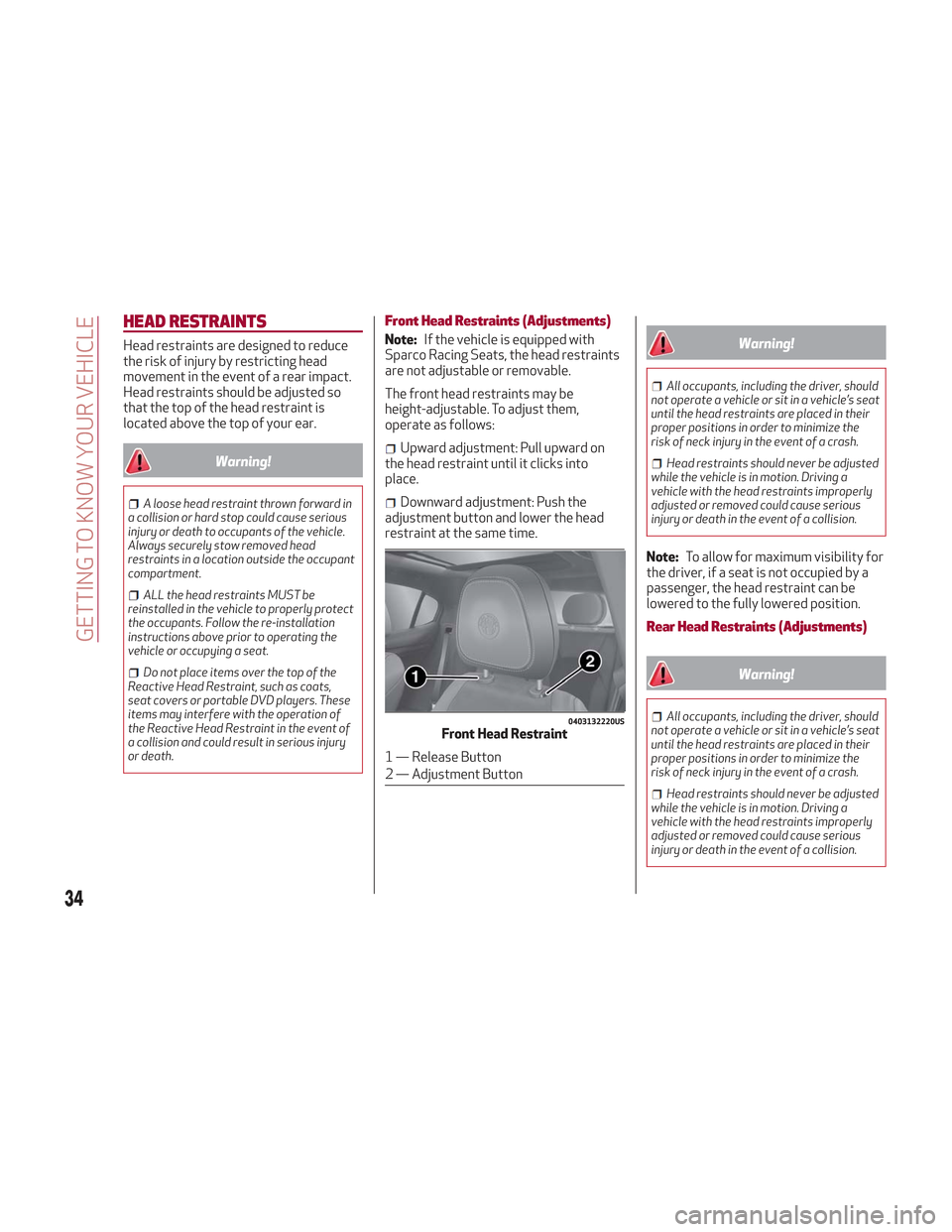
Downward adjustment: Push the
adjustment button and lower the head
restraint at the same time.
Warning!
All occupants, including the driver, should
not operate a vehicle or sit in a vehicle’s seat
until the head restraints are placed in their
proper positions in order to minimize the
risk of neck injury in the event of a crash.
Head restraints should never be adjusted
while the vehicle is in motion. Driving a
vehicle with the head restraints improperly
adjusted or removed could cause serious
injury or death in the event of a collision.
Note: To allow for maximum visibility for
the driver, if a seat is not occupied by a
passenger, the head restraint can be
lowered to the fully lowered position.
Rear Head Restraints (Adjustments)
Warning!
All occupants, including the driver, should
not operate a vehicle or sit in a vehicle’s seat
until the head restraints are placed in their
proper positions in order to minimize the
risk of neck injury in the event of a crash.
Head restraints should never be adjusted
while the vehicle is in motion. Driving a
vehicle with the head restraints improperly
adjusted or removed could cause serious
injury or death in the event of a collision.
0403132220USFront Head Restraint
1 — Release Button
2 — Adjustment Button
34
GETTING TO KNOW YOUR VEHICLE
Page 37 of 276
The height of the outboard head
restraints can be adjusted. The head
restraint of the center seat, if equipped,
cannot be adjusted, only removed.
For upward adjustment, pull upward on
the head restraint until it clicks into
place.
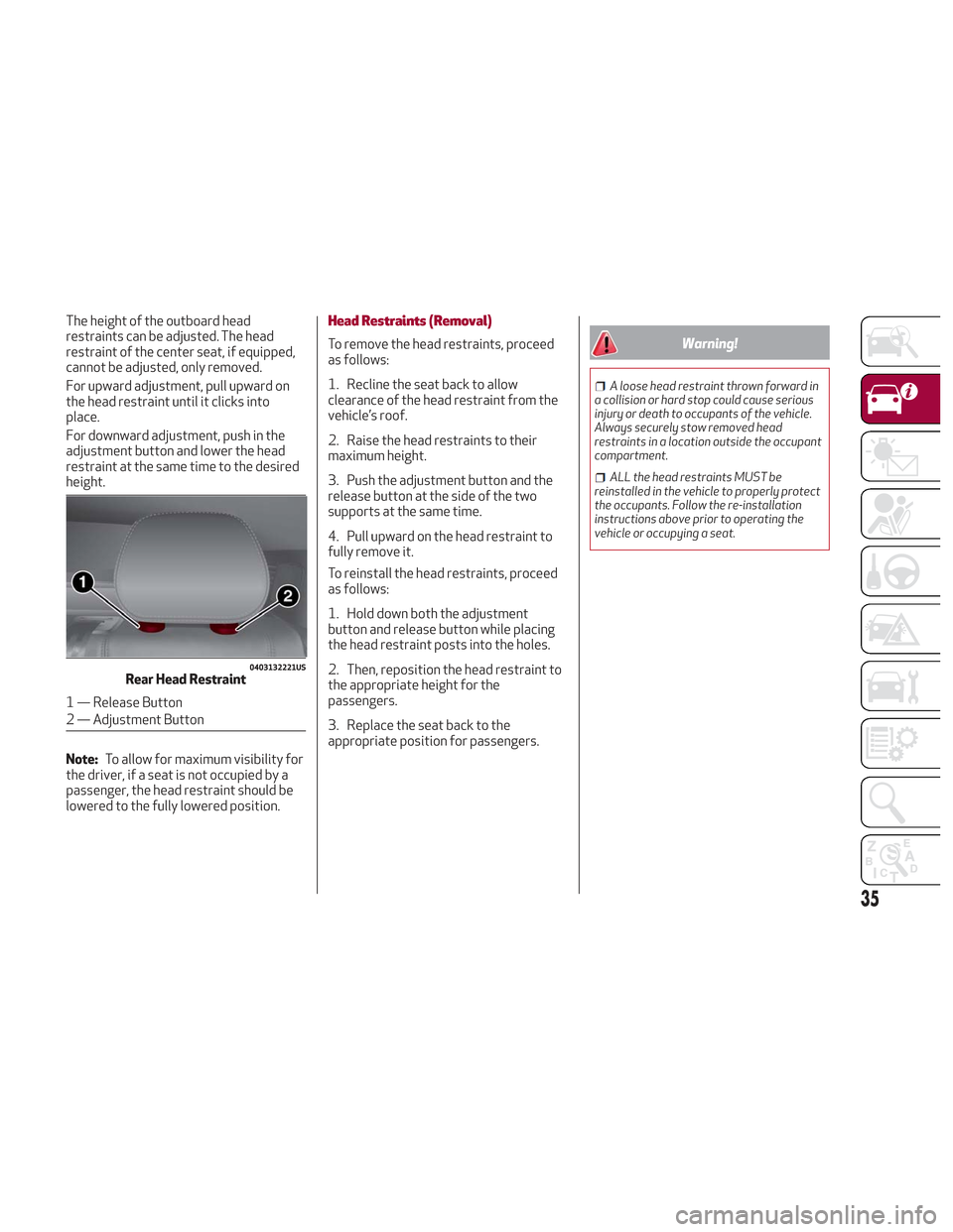
For downward adjustment, push in the
adjustment button and lower the head
restraint at the same time to the desired
height.
Note:To allow for maximum visibility for
the driver, if a seat is not occupied by a
passenger, the head restraint should be
lowered to the fully lowered position.Head Restraints (Removal)
To remove the head restraints, proceed
as follows:
1. Recline the seat back to allow
clearance of the head restraint from the
vehicle’s roof.
2. Raise the head restraints to their
maximum height.
3. Push the adjustment button and the
release button at the side of the two
supports at the same time.
4. Pull upward on the head restraint to
fully remove it.
To reinstall the head restraints, proceed
as follows:
1. Hold down both the adjustment
button and release button while placing
the head restraint posts into the holes.
2. Then, reposition the head restraint to
the appropriate height for the
passengers.
3. Replace the seat back to the
appropriate position for passengers.Warning!
A loose head restraint thrown forward in
a collision or hard stop could cause serious
injury or death to occupants of the vehicle.
Always securely stow removed head
restraints in a location outside the occupant
compartment.
ALL the head restraints MUST be
reinstalled in the vehicle to properly protect
the occupants. Follow the re-installation
instructions above prior to operating the
vehicle or occupying a seat.
0403132221USRear Head Restraint
1 — Release Button
2 — Adjustment Button
35
Page 50 of 276
Automatic Dual-Zone Climate Control System
Controls
Caution!
The system uses R1234yf refrigerant, which does not pollute the environment in the event of accidental leakage. Under no circumstances, use
R134a and R12 fluids, which are incompatible with the components of this system.
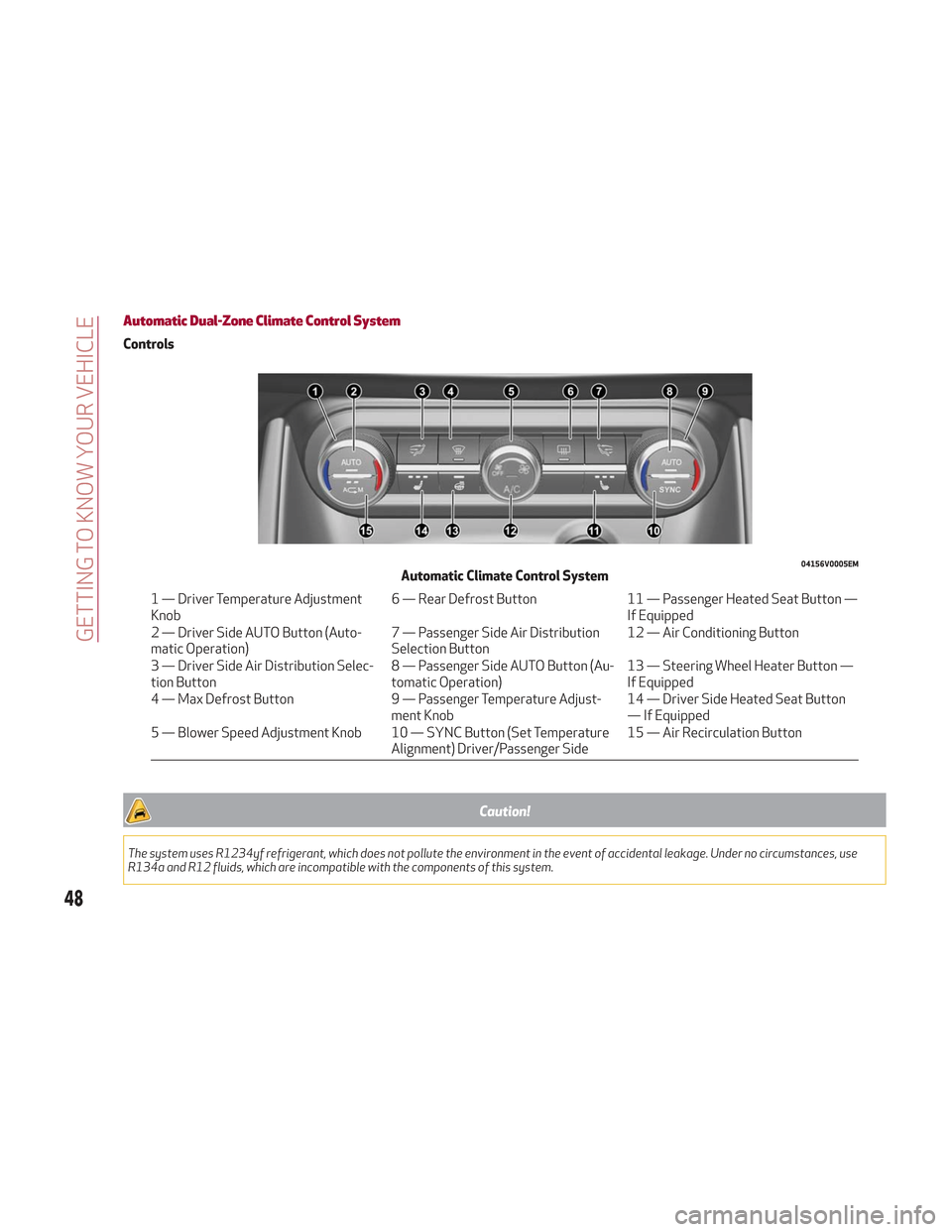
04156V0005EMAutomatic Climate Control System
1 — Driver Temperature Adjustment
Knob6 — Rear Defrost Button
11 — Passenger Heated Seat Button —
If Equipped
2 — Driver Side AUTO Button (Auto-
matic Operation) 7 — Passenger Side Air Distribution
Selection Button12 — Air Conditioning Button
3 — Driver Side Air Distribution Selec-
tion Button 8 — Passenger Side AUTO Button (Au-
tomatic Operation)13 — Steering Wheel Heater Button —
If Equipped
4 — Max Defrost Button 9 — Passenger Temperature Adjust-
ment Knob 14 — Driver Side Heated Seat Button
— If Equipped
5 — Blower Speed Adjustment Knob 10 — SYNC Button (Set Temperature Alignment) Driver/Passenger Side15 — Air Recirculation Button
48
GETTING TO KNOW YOUR VEHICLE
Page 123 of 276
Warning!
Wearing your seat belt incorrectly could
make your injuries in a collision much worse.
You might suffer internal injuries, or you
could even slide out of the seat belt. Follow
these instructions to wear your seat belt
safely and to keep your passengers safe,
too.
Position the shoulder belt across the
shoulder and chest with minimal, if any slack
so that it is comfortable and not resting on
your neck. The retractor will withdraw any
slack in the shoulder belt.
Misadjustment of the seat belt could
reduce the effectiveness of the safety belt
in a crash.
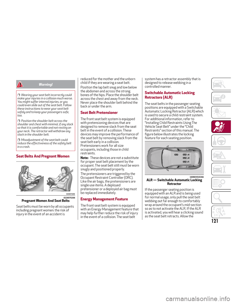
Seat Belts And Pregnant Women
Seat belts must be worn by all occupants
including pregnant women: the risk of
injury in the event of an accident is reduced for the mother and the unborn
child if they are wearing a seat belt.
Position the lap belt snug and low below
the abdomen and across the strong
bones of the hips. Place the shoulder belt
across the chest and away from the neck.
Never place the shoulder belt behind the
back or under the arm.
Seat Belt Pretensioner
The front seat belt system is equipped
with pretensioning devices that are
designed to remove slack from the seat
belt in the event of a collision. These
devices may improve the performance of
the seat belt by removing slack from the
seat belt early in a collision.
Pretensioners work for all size
occupants, including those in child
restraints.
Note:
These devices are not a substitute
for proper seat belt placement by the
occupant. The seat belt still must be worn
snugly and positioned properly.
The pretensioners are triggered by the
Occupant Restraint Controller (ORC).
Like the air bags, the pretensioners are
single use items. A deployed
pretensioner or a deployed air bag must
be replaced immediately.
Energy Management Feature
The front seat belt system is equipped
with an Energy Management feature that
may help further reduce the risk of injury
in the event of a collision. The seat belt system has a retractor assembly that is
designed to release webbing in a
controlled manner.
Switchable Automatic Locking
Retractors (ALR)
The seat belts in the passenger seating
positions are equipped with a Switchable
Automatic Locking Retractor (ALR) which
is used to secure a child restraint system.
For additional information, refer to
“Installing Child Restraints Using The
Vehicle Seat Belt” under the “Child
Restraints” section of this manual. The
figure below illustrates the locking
feature for each seating position.
If the passenger seating position is
equipped with an ALR and is being used
for normal usage, only pull the seat belt
webbing out far enough to comfortably
wrap around the occupant’s mid-section
so as to not activate the ALR. If the ALR
is activated, you will hear a clicking sound
as the seat belt retracts. Allow the
0226075266Pregnant Women And Seat Belts
16086V0101NAALR — Switchable Automatic Locking
Retractor
121
Page 164 of 276

System Activation
The activation of the system is indicated
by the
symbol lighting up on the
display. In this condition, the light on the
button is off.
System Deactivation
A message will appear on the display
when the system is deactivated. In this
condition, the light on the button is on.
Note: Each time the engine is started,
the system is activated regardless of
where was when it was previously
switched off.
Possible Reasons The Engine Does Not
Autostop
For higher comfort and increased safety,
and to reduce emissions, there are
certain conditions where the engine will
not autostop despite the system being
active, such as:
Engine still cold.
Especially cold outside temperature.
Battery not sufficiently charged.
Driver's door not shut.
Driver's seat belt not fastened.
Reverse gear engaged (e.g. for parking
maneuvers).
With the automatic climate control
active, an adequate cabin heating or
cooling comfort has not been reached or
with MAX-DEF function active.
During the first period of use, to
initialize the system.
Steering angle beyond threshold.
Engine Restarting Conditions
Due to comfort, emission control, and
safety reasons, the engine can restart
automatically without any action by the
driver, under special conditions, such as:
Battery not sufficiently charged.
Reduced braking system vacuum (e.g.
if the brake pedal is pressed repeatedly).
Vehicle moving (e.g. when driving on
roads with a grade).
Engine stopping by the Stop/Start
system for more than approx. three
minutes.
With the automatic climate control
active, an adjustment in cabin heating or
cooling is made or with MAX-DEF
function active.
Safety Functions
When the engine is stopped through the
Stop/Start system, if the driver releases
their seat belt, opens the driver's or
passenger's door, or opens the hood from
inside the vehicle, the engine can be
restarted only by using the ignition.
This condition is indicated to the driver
both through a buzzer and a message on
the instrument cluster display.
Energy Saving Function
If the driver does not carry out any action
for more than three minutes after the
automatic engine restart, the Start/Stop
system will switch off the engine in order
to prevent fuel consumption.
In this situation, the engine can only be
restarted using the ignition device.
Note: It is possible to keep the engine
running by deactivating the system.
Irregular Operation
In the event of malfunction, the
Stop/Start system is deactivated.
For failure indications, refer to "Warning
Lights and Messages" paragraph in
"Getting To Know Your Instrument Panel".
Vehicle Inactivity
In the event of vehicle inactivity (or if the
battery is replaced), special attention
must be paid to the disconnection of the
battery power supply.
Proceed as follows:
Remove connector from socket to
disconnect sensor (battery status
monitoring) installed on the negative pole
of the battery. This sensor should never
be disconnected from the pole except if
the battery is replaced.
162
STARTING AND OPERATING
Page 270 of 276

Cooling SystemCoolant Capacity ...........257
Selection Of Coolant (Antifreeze) ..................... .257
Courtesy Mirror Light (Bulb Replacement) .............191
Cruise Control (Speed Control) . . . .166
Cupholder ..................67
Cupholders .................67
Customer Assistance ..........262
Daytime Running Lights ..........39
Daytime Running Lights (DRL) ......39
Defroster, Windshield ..........142
Dimensions ............... .253
Direction Indicators (Changing A Bulb) .................. .191
Disabled Vehicle Towing .........204
Door Light ..................43
Door Locks Child-Protection Door Lock —
Rear Doors ................27
Power Door Locks ...........27
Doors .....................23
Drive Train Control (DTC) System . . .104
Driving Modes ............. .158
Dynamic Steering Torque (DST) System ................ .107
Electric Park Brake ............149
Electric Remote Mirrors .........37Electric Steering Wheel Heating
.....37
Electronic Speed Control ........164
Electronic Speed Control (Cruise Control) ............. .164,166
Electronic Stability Control (ESC) System ................ .105
Emergency, In Case Of ..........198
Hazard Warning Flasher .......188
Jacking ................ .225
Jump Starting .............201
Overheating ............. .203
Towing ..............204,206
Emission Control System Maintenance ............. .101
Engine .................. .247
Block Heater ............. .149
Engine Coolant Level ........
.216
Exhaust
Gas Caution .........141
Fuel Requirements ..........255
Jump Starting .............201
Oil................... .257
Oil Selection ............. .257
Overheating ............. .203
Starting ............... .203
Engine Compartment ..........215
Engine Compartment (Washing) . . . .244
Engine Oil Level Check ............. .216
Engine Overheating ...........203 Enhanced Accident Response
Feature ..............129,207
Ethanol .................. .255
Exhaust Gas Caution ...........141
Exhaust System .............141
Exterior Lighting ............38,40
Exterior Lights ............38,143
Flashers Hazard Warning ............188
Turn Signal ............41,143
Fluid Capacities ..............257
Fluid Leaks ............... .143
Fluids And Lubricants ..........258
Forward Collision Warning (System) .110
Front Light Cluster With Main Beam Xenon Gas Discharge Headlights
(Bulb Replacement) ..........191
Front Seat Electric Heating .......31
Front Seats (Power Adjustment) ....29
Front Wipers Wiper Operation ............45
Fuel Additives ............... .256
Clean Air ............... .255
Ethanol ................ .255
Materials Added ...........256
Methanol ............... .255
Tank Capacity .............257
INDEX