2018 Alfa Romeo Stelvio outlet
[x] Cancel search: outletPage 68 of 276

2. When the HomeLink indicator begins
to flash slowly, move the portable remote
control 1 to 3 inches from the system
(keeping the programmable button
pressed down).
If the indicator does not begin to flash
quickly, change the distance between the
HomeLink and the portable remote
control and try the procedure again.
The HomeLink indicator flashes, first
slowly and then quickly. When the
indicator starts to flash quickly, release
both buttons on the remote control.
The system previously programmed to
HomeLink has now been deleted and the
new system is ready to use. This does not
affect the other two HomeLink buttons in
any way.
Deleting Programmed Keys
It is recommended to delete HomeLink
programming before selling the vehicle.
All three keys are deleted
simultaneously.
Proceed as follows:
1. Push and hold the outer buttons
(1 and 3). After about ten seconds, the
indicator will start to flash.
2. Release both keys. Technical Information For After Sales
Service
If you are unable to set up HomeLink
successfully after following the above
instructions, contact After Sales Service
(HomeLink free hotline number
1-800-355-3515 ) with the following
information:
Vehicle make and model, including
manufacturing year and country of
purchase;
Make, model, age and frequency of use
of the original portable remote control (if
known).
General Information
The following regulatory statement
applies to all Radio Frequency (RF)
devices equipped in this vehicle:
This device complies with Part 15 of the
FCC Rules and with Industry Canada
license-exempt RSS standard(s).
Operation is subject to the following two
conditions:
1. This device may not cause harmful
interference, and
2. This device must accept any
interference received, including
interference that may cause undesired
operation.
Note: Changes or modifications not
expressly approved by the party
responsible for compliance could void the
user’s authority to operate the
equipment.
Power Outlets
The Instrument Panel Power Outlet is
located under the air conditioning control
panel. It will only operate when the
ignition is ON.
Note: Do not connect devices, with a
power rating higher than 180 W, to the
outlet. Do not use power adaptors that
do not fit the outlet as this may damage
it.
0313132162USInstrument Panel Power Outlet
66
GETTING TO KNOW YOUR VEHICLE
Page 69 of 276
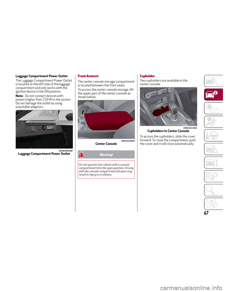
Luggage Compartment Power Outlet
The Luggage Compartment Power Outlet
is located on the left side of the luggage
compartment and only works with the
ignition device in the ON position.
Note:Do not connect devices with
powers higher than 150 W to the socket.
Do not damage the outlet by using
unsuitable adaptors.Front Armrest
The center console storage compartment
is located between the front seats.
To access the center console storage, lift
the upper part of the center console as
shown below.
Warning!
Do not operate this vehicle with a console
compartment lid in the open position. Driving
with the console compartment lid open may
result in injury in a collision.
Cupholder
Two cupholders are available in the
center console.
To access the cupholders, slide the cover
forward. To close the compartment, push
the cover and it will close automatically.
04206V0010EMLuggage Compartment Power Outlet
0403132209USCenter Console
0403132213USCupholders In Center Console
67
Page 151 of 276
ENGINE BLOCK HEATER — IF
EQUIPPED
The engine block heater warms the
engine and permits quicker starts in cold
weather.
Connect the cord to a 110-115 Volt AC
electrical outlet with a grounded,
three-wire extension cord.
For ambient temperatures below 0°F
(-18°C), the engine block heater is
recommended. For ambient
temperatures below -20°F (-29°C), the
engine block heater is required.
The engine block heater cord is routed
under the hood, behind to the driver’s
side headlamp. Follow the steps below to
properly use the engine block heater:
1. Locate the engine block heater cord
(access door on the passenger side wiper
cowl).
2. Pull the cord to the front of the
vehicle and plug it into a grounded,
three-wire extension cord.
3. After the vehicle is running, properly
stow away behind access door on the
passenger side wiper cowl.Note:
The engine block heater cord is a
factory installed option. If your vehicle is
not equipped, heater cords are available
from your authorized dealer.
The engine block heater will require
110 Volts AC and 6.5 Amps to activate
the heater element.
The engine block heater must be
plugged in at least 1 hour to have a
warming effect on the engine and at
least 4 hours to have a warming effect
when ambient temperatures are below
-20 F (-29 C)
Warning!
Remember to disconnect the engine block
heater cord before driving. Damage to the
110-115 Volt electrical cord could cause
electrocution.
ELECTRIC PARK BRAKE
The vehicle is equipped with electric park
brake to guarantee better use and
optimal performance compared to a
manually operated park brake.
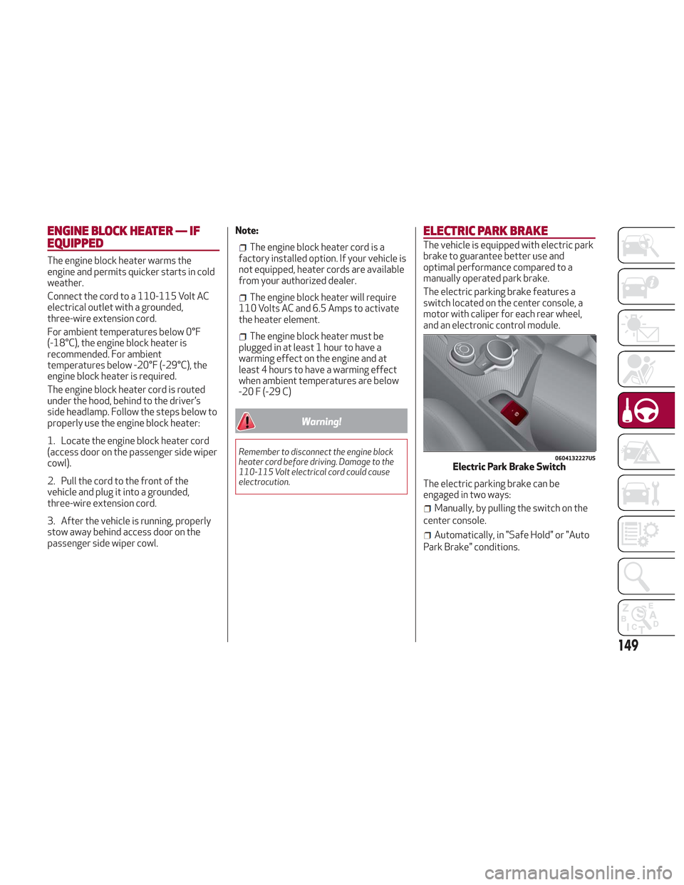
The electric parking brake features a
switch located on the center console, a
motor with caliper for each rear wheel,
and an electronic control module.
The electric parking brake can be
engaged in two ways:
Manually, by pulling the switch on the
center console.
Automatically, in "Safe Hold" or "Auto
Park Brake" conditions.
0604132227USElectric Park Brake Switch
149
Page 195 of 276
3. Install bulb, making sure that it is
correctly inserted fully.
4. Close the protective cover on the lens.
5. Install liftgate lamp in the correct
position, inserting it first on one side, and
then pressing on the other side until it
clicks into place.
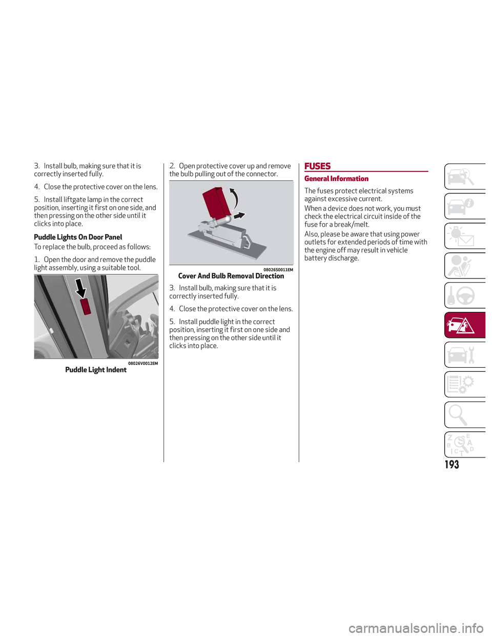
Puddle Lights On Door Panel
To replace the bulb, proceed as follows:
1. Open the door and remove the puddle
light assembly, using a suitable tool.2. Open protective cover up and remove
the bulb pulling out of the connector.
3. Install bulb, making sure that it is
correctly inserted fully.
4. Close the protective cover on the lens.
5. Install puddle light in the correct
position, inserting it first on one side and
then pressing on the other side until it
clicks into place.FUSES
General Information
The fuses protect electrical systems
against excessive current.
When a device does not work, you must
check the electrical circuit inside of the
fuse for a break/melt.
Also, please be aware that using power
outlets for extended periods of time with
the engine off may result in vehicle
battery discharge.
08026V0012EMPuddle Light Indent
08026S0011EMCover And Bulb Removal Direction
193
Page 201 of 276
Inflation Procedure
Warning!
Do not attempt to seal a tire on the side of
the vehicle closest to traffic. Pull far enough
off the road to avoid the danger of being hit
when using the Tire Service Kit.
Do not use Tire Service Kit or drive the
vehicle under the following circumstances:
If the puncture in the tire tread is
approximately 1/4 inch (6 mm) or larger.
If the tire has any sidewall damage.
If the tire has any damage from driving
with extremely low tire pressure.
If the tire has any damage from driving on
a flat tire.
If the wheel has any damage.
If you are unsure of the condition of the
tire or the wheel.
Keep Tire Service Kit away from open
flames or heat sources.
A loose Tire Service Kit thrown forward in
a collision or hard stop could endanger the
occupants of the vehicle. Always stow the
Tire Service Kit in the place provided. Failure
to follow these warnings can result in
injuries that are serious or fatal to you, your
passengers, and others around you.
Take care not to allow the contents of Tire
Service Kit to come in contact with hair,
eyes, or clothing. Tire Service Kit sealant is
harmful if inhaled, swallowed, or absorbed through the skin. It causes skin, eye, and
respiratory irritation. Flush immediately
with plenty of water if there is any contact
with eyes or skin. Change clothing as soon
as possible, if there is any contact with
clothing.
Tire Service Kit Sealant solution contains
latex. In case of an allergic reaction or rash,
consult a physician immediately. Keep Tire
Service Kit out of reach of children. If
swallowed, rinse mouth immediately with
plenty of water and drink plenty of water.
Do not induce vomiting! Consult a physician
immediately.
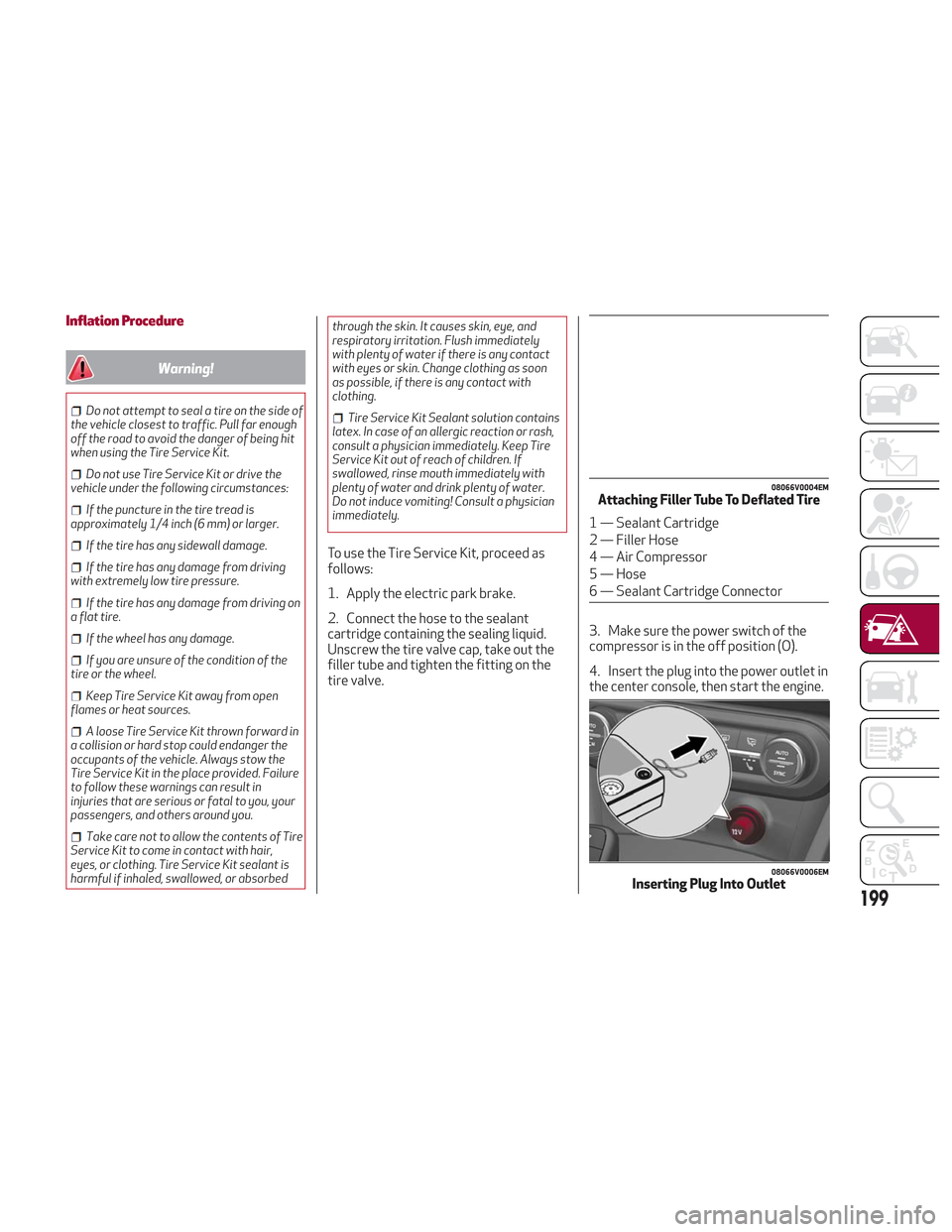
To use the Tire Service Kit, proceed as
follows:
1. Apply the electric park brake.
2. Connect the hose to the sealant
cartridge containing the sealing liquid.
Unscrew the tire valve cap, take out the
filler tube and tighten the fitting on the
tire valve. 3. Make sure the power switch of the
compressor is in the off position (O).
4. Insert the plug into the power outlet in
the center console, then start the engine.
08066V0004EMAttaching Filler Tube To Deflated Tire
1 — Sealant Cartridge
2 — Filler Hose
4 — Air Compressor
5 — Hose
6 — Sealant Cartridge Connector
08066V0006EMInserting Plug Into Outlet
199
Page 202 of 276
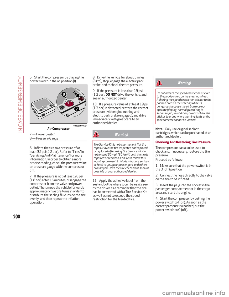
5. Start the compressor by placing the
power switch in the on position (I).
6. Inflate the tire to a pressure of at
least 32 psi (2.2 bar). Refer to “Tires” in
“Servicing And Maintenance” for more
information. In order to obtain a more
precise reading, check the pressure value
on pressure gauge with the compressor
off.
7. If the pressure is not at least 26 psi
(1.8 bar) after 15 minutes, disengage the
compressor from the valve and power
outlet. Then, move the vehicle forwards
approximately five tire turns in order to
distribute the sealing fluid inside the tire
evenly, and then repeat the inflation
operation.8. Drive the vehicle for about 5 miles
(8 km), stop, engage the electric park
brake, and recheck the tire pressure.
9. If the pressure is less than 19 psi
(1.3 bar),
DO NOTdrive the vehicle, and
see an authorized dealer.
10. If a pressure value of at least 19 psi
(1.3 bar) is detected, restore the correct
pressure (with engine running and
electric park brake engaged), and drive
immediately with great care to an
authorized dealer.
Warning!
Tire Service Kit is not a permanent flat tire
repair. Have the tire inspected and repaired
or replaced after using Tire Service Kit. Do
not exceed 50 mph (80 km/h) until the tire is
repaired or replaced. Failure to follow this
warning can result in injuries that are serious
or fatal to you, your passengers, and others
around you. Have the tire checked as soon as
possible at your authorized dealer.
11. Apply the adhesive label from the
sealant bottle where it can be easily seen
by the driver as a reminder that the tire
has been treated with a Tire Service Kit,
as well as not to exceed the speed
restriction for the treated tire.
Warning!
Do not adhere the speed restriction sticker
to the padded area on the steering wheel.
Adhering the speed restriction sticker to the
padded area on the steering wheel is
dangerous because the air bag may not
operate (deploy) normally resulting in
serious injury. In addition, do not adhere the
sticker to areas where warning lights or the
speedometer cannot be viewed.
Note: Only use original sealant
cartridges, which can be purchased at an
authorized dealer.
Checking And Restoring Tire Pressure
The compressor can also be used to
check and, if necessary, restore the tire
pressure.
Proceed as follows:
1. Make sure that the power switch is in
the O (off) position.
2. Connect the hose directly to the valve
on the tire to be inflated.
3. Insert the plug into the socket in the
passenger compartment or in the cargo
area and start the engine.
4. Start the compressor by putting the
power switch to I (on). As soon as the
correct pressure is reached, put the
power switch to O (off).
08066V0005EMAir Compressor
7 — Power Switch
8 — Pressure Gauge
200
IN CASE OF EMERGENCY
Page 205 of 276
Cable Disconnection
Once the engine is started, remove the
connection cables in reverse sequence,
as described below:
1. Disconnect the negative (-) end of the
jumper cable from the remote negative (-)
post of the vehicle with the discharged
battery.
2. Disconnect the negative end (-) of the
jumper cable from the negative (-) post of
the booster battery.
3. Disconnect the opposite end of the
positive (+) jumper cable from the
positive (+) post of the booster battery.
4. Disconnect the positive (+) end of the
jumper cable from the positive (+) post of
the vehicle with the discharged battery.
If frequent jump starting is required to
start your vehicle, you should have the
battery and charging system inspected at
an authorized dealer.
Caution!
Accessories plugged into the vehicle power
outlets draw power from the vehicle’s
battery, even when not in use (i.e., cellular
phones, etc.). Eventually, if plugged in long
enough without engine operation, the
vehicle’s battery will discharge sufficiently
to degrade battery life and/or prevent the
engine from starting.
Bump Starting
Never jump start the engine by pushing,
towing or coasting downhill. You cannot
start a vehicle with an automatic
transmission by pushing it.
Caution!
Accessories plugged into the vehicle power
outlets draw power from the vehicle’s
battery, even when not in use (i.e., cellular
phones, etc.). Eventually, if plugged in long
enough without engine operation, the
vehicle’s battery will discharge sufficiently
to degrade battery life and/or prevent the
engine from starting.
ENGINE OVERHEATING
Engine overheating may occur in
situations such as (but not limited to)
extreme environmental temperatures or
frequent engine stops/starts. If the
engine becomes overheated, the Engine
Temperature Warning Light in the
instrument cluster will illuminate along
with a dedicated message. Refer to
"Warning Lights And Messages On The
Instrument Panel" in the "Getting To
Know Your Instrument Panel" for more
information.
In any of the following situations, you can
reduce the potential for overheating by
taking the appropriate action.
On the highways — slow down.
In city traffic — while stopped, place
the transmission in NEUTRAL, but do not
increase engine idle speed.
Note: There are steps that you can take
to slow down an impending overheat
condition:
If your air conditioner (A/C) is on, turn
it off. The A/C system adds heat to the
engine cooling system and turning the
A/C off can help remove this heat.
You can also turn the temperature
control to maximum heat, the mode
control to floor and the blower control to
high. This allows the heater core to act
as a supplement to the radiator and aids
in removing heat from the engine cooling
system.
203