2018 Alfa Romeo Stelvio lights
[x] Cancel search: lightsPage 189 of 276
IN CASE OF EMERGENCY
Have a flat tire or a burnt-out bulb?
At times, a problem such as these may
interfere with your driving experience.
The section on emergencies can help you
to deal with critical situations
independently.
In an emergency, we recommend that you
call the phone number found in the
Warranty Book.
You may also consider contacting an
authorized dealer.HAZARD WARNING LIGHTS.....188
BULB REPLACEMENT .........188
FUSES .................. .193
TIRE SERVICE KIT ............198
JUMP STARTING ............201
ENGINE OVERHEATING ........203
TOWING A DISABLED VEHICLE . . .204
TOW EYES ............... .206
ENHANCED ACCIDENT RESPONSE
SYSTEM (EARS) .............207
EVENT DATA RECORDER (EDR) . . .207
187
Page 190 of 276

HAZARD WARNING LIGHTS
The Hazard Warning flasher switch is
located in the switch bank below the
radio screen.Push the switch once to
turn the hazard warning
flasher on. When the
switch is activated, all
directional turn signals
will flash on and off to
warn oncoming traffic
of an emergency. Push the switch a
second time to turn the hazard warning
flashers off.
This is an emergency warning system and
it should not be used when the vehicle is
in motion. Use it when your vehicle is
disabled and is creating a safety hazard
for other motorists.
When you must leave the vehicle to seek
assistance, the hazard warning flashers
will continue to operate even though the
ignition is cycled to STOP.
Caution!
Prolonged use of the hazard warning
flashers may discharge the vehicle’s battery.
Panic Brake Assist (PBA) System
The PBA system is designed to improve
the vehicle’s braking capacity during
emergency braking.
For further details about the Panic Brake
Assist System, refer to the "Active
Safety Systems" section in the "Safety"
chapter.
BULB REPLACEMENT
General Instructions
Before replacing a bulb, check the
contacts for oxidation.
Replace blown bulbs with others of the
same type and power.
After replacing a headlight bulb,
always check its alignment.
When a light is not working, check that
the corresponding fuse is intact before
changing the bulb. For the location of
fuses, refer to “Fuses” in this chapter.
Note: In some particular climate
conditions, such as low temperature,
humidity, or after washing the vehicle, a
thin condensation layer may form on the
internal surfaces of the front and rear
headlights. This condensation will
disappear after switching on the
headlights.
0403132206USHazard Warning Switch
188
IN CASE OF EMERGENCY
Page 192 of 276

Replacement Bulbs
Light bulbsTypePower
Front direction indicators
(*)PY24W 24W
Rear Fog lights
(*)H11 55 W
Main beam headlights, front side lights/daylight running lights (DRL)
(*)H15 55/15W
Dipped beam headlights
(*)H7 55W
Main beam/dipped beam headlights (Xenon gas discharge) D3S35W
Sun visor light 1.5CP2.1W
Glove compartment light W5W4W
Liftgate light W5W5W
Puddle lights (under door panel) W5W5W
(*) Only for basic version headlight with halogen main beam/dipped beam headlights
190
IN CASE OF EMERGENCY
Page 193 of 276

Replacing Exterior Bulbs
Warning!
Only replace bulbs when the engine is off.
Also ensure that the engine is cold, to
prevent the risk of burns.
Front Light Cluster
Direction Indicators
Proceed with the directions below to
change bulbs:
1. Operating inside the engine
compartment, locate the protective
cover.
2. Remove protective cover.3. Turn the bulb/connector assembly
counterclockwise, and then slide it off
the headlight body.
4. Remove the bulb by sliding it off the
bulb holder.
5. Install the new bulb, making sure it is
correctly inserted in the bulb holder.6. Insert the bulb/connector assembly in
the housing on the headlight body and
turn it clockwise, making sure that it is
locked correctly.
7. Install the protective cover.
Front Light Cluster With Main Beam
Xenon Gas Discharge Headlights
To replace the bulbs of the main beam
headlights, contact an authorized dealer.
Caution!
Do not touch the new bulb with your fingers.
Oil contamination will severely shorten bulb
life. If the bulb comes in contact with any oily
surface, clean the bulb with rubbing alcohol.
Replacing Interior Bulbs
Courtesy Mirror Light
To replace the bulbs, proceed as follows:
1. Lift the mirror cover and remove the
lens, using a suitable tool.
08026V0023EMProtective Cover Location
08026V0006EMProtective Cover
08026V0007EMBulb/Connector
191
Page 194 of 276
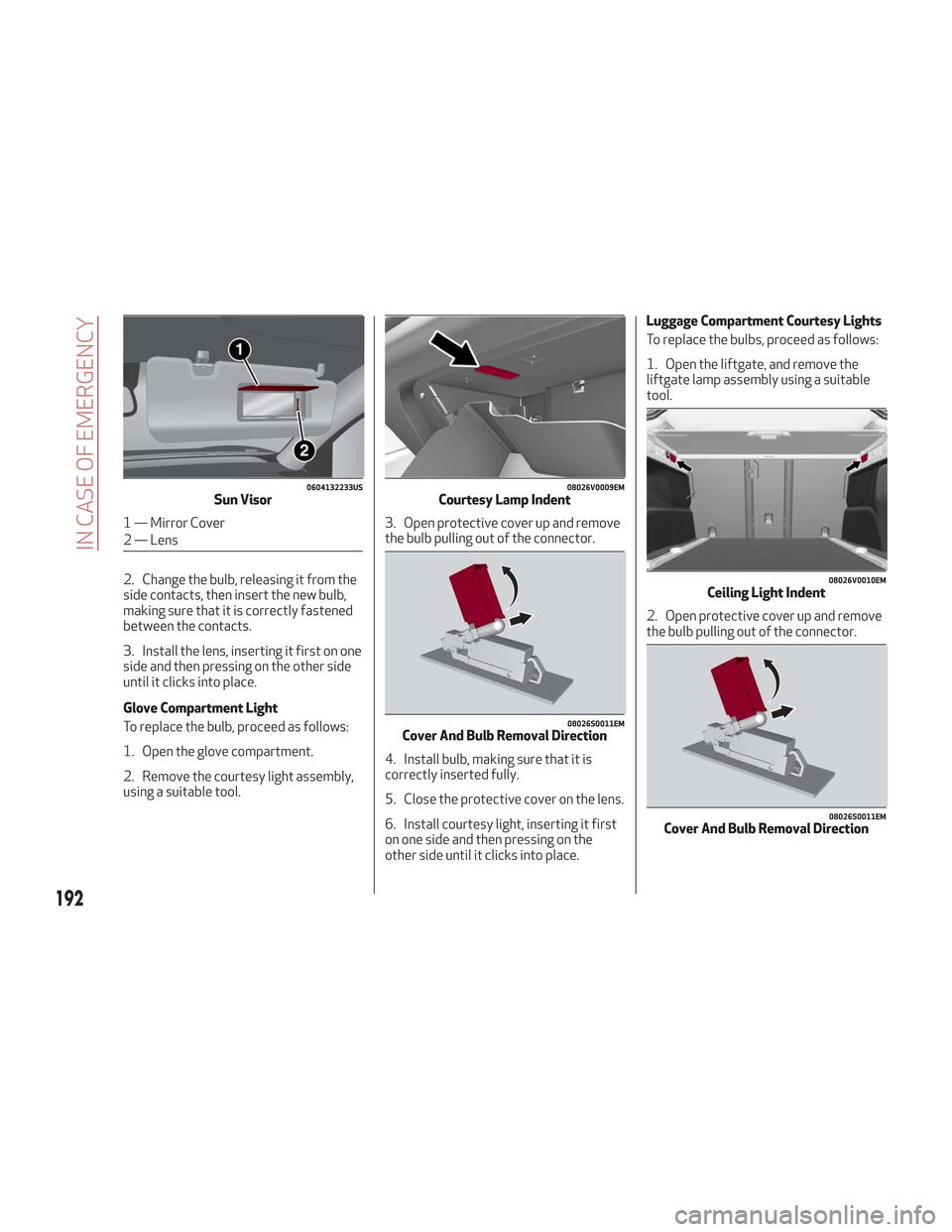
2. Change the bulb, releasing it from the
side contacts, then insert the new bulb,
making sure that it is correctly fastened
between the contacts.
3. Install the lens, inserting it first on one
side and then pressing on the other side
until it clicks into place.
Glove Compartment Light
To replace the bulb, proceed as follows:
1. Open the glove compartment.
2. Remove the courtesy light assembly,
using a suitable tool.3. Open protective cover up and remove
the bulb pulling out of the connector.
4. Install bulb, making sure that it is
correctly inserted fully.
5. Close the protective cover on the lens.
6. Install courtesy light, inserting it first
on one side and then pressing on the
other side until it clicks into place.Luggage Compartment Courtesy Lights
To replace the bulbs, proceed as follows:
1. Open the liftgate, and remove the
liftgate lamp assembly using a suitable
tool.
2. Open protective cover up and remove
the bulb pulling out of the connector.
0604132233USSun Visor
1 — Mirror Cover
2 — Lens
08026V0009EMCourtesy Lamp Indent
08026S0011EMCover And Bulb Removal Direction
08026V0010EMCeiling Light Indent
08026S0011EMCover And Bulb Removal Direction
192
IN CASE OF EMERGENCY
Page 195 of 276
3. Install bulb, making sure that it is
correctly inserted fully.
4. Close the protective cover on the lens.
5. Install liftgate lamp in the correct
position, inserting it first on one side, and
then pressing on the other side until it
clicks into place.
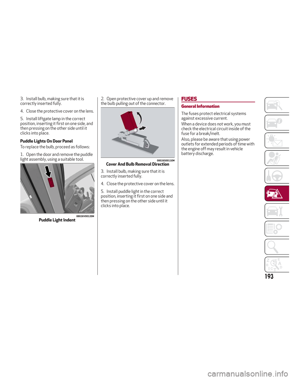
Puddle Lights On Door Panel
To replace the bulb, proceed as follows:
1. Open the door and remove the puddle
light assembly, using a suitable tool.2. Open protective cover up and remove
the bulb pulling out of the connector.
3. Install bulb, making sure that it is
correctly inserted fully.
4. Close the protective cover on the lens.
5. Install puddle light in the correct
position, inserting it first on one side and
then pressing on the other side until it
clicks into place.FUSES
General Information
The fuses protect electrical systems
against excessive current.
When a device does not work, you must
check the electrical circuit inside of the
fuse for a break/melt.
Also, please be aware that using power
outlets for extended periods of time with
the engine off may result in vehicle
battery discharge.
08026V0012EMPuddle Light Indent
08026S0011EMCover And Bulb Removal Direction
193
Page 202 of 276
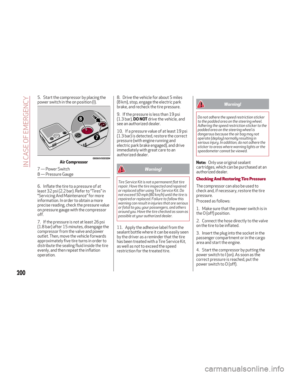
5. Start the compressor by placing the
power switch in the on position (I).
6. Inflate the tire to a pressure of at
least 32 psi (2.2 bar). Refer to “Tires” in
“Servicing And Maintenance” for more
information. In order to obtain a more
precise reading, check the pressure value
on pressure gauge with the compressor
off.
7. If the pressure is not at least 26 psi
(1.8 bar) after 15 minutes, disengage the
compressor from the valve and power
outlet. Then, move the vehicle forwards
approximately five tire turns in order to
distribute the sealing fluid inside the tire
evenly, and then repeat the inflation
operation.8. Drive the vehicle for about 5 miles
(8 km), stop, engage the electric park
brake, and recheck the tire pressure.
9. If the pressure is less than 19 psi
(1.3 bar),
DO NOTdrive the vehicle, and
see an authorized dealer.
10. If a pressure value of at least 19 psi
(1.3 bar) is detected, restore the correct
pressure (with engine running and
electric park brake engaged), and drive
immediately with great care to an
authorized dealer.
Warning!
Tire Service Kit is not a permanent flat tire
repair. Have the tire inspected and repaired
or replaced after using Tire Service Kit. Do
not exceed 50 mph (80 km/h) until the tire is
repaired or replaced. Failure to follow this
warning can result in injuries that are serious
or fatal to you, your passengers, and others
around you. Have the tire checked as soon as
possible at your authorized dealer.
11. Apply the adhesive label from the
sealant bottle where it can be easily seen
by the driver as a reminder that the tire
has been treated with a Tire Service Kit,
as well as not to exceed the speed
restriction for the treated tire.
Warning!
Do not adhere the speed restriction sticker
to the padded area on the steering wheel.
Adhering the speed restriction sticker to the
padded area on the steering wheel is
dangerous because the air bag may not
operate (deploy) normally resulting in
serious injury. In addition, do not adhere the
sticker to areas where warning lights or the
speedometer cannot be viewed.
Note: Only use original sealant
cartridges, which can be purchased at an
authorized dealer.
Checking And Restoring Tire Pressure
The compressor can also be used to
check and, if necessary, restore the tire
pressure.
Proceed as follows:
1. Make sure that the power switch is in
the O (off) position.
2. Connect the hose directly to the valve
on the tire to be inflated.
3. Insert the plug into the socket in the
passenger compartment or in the cargo
area and start the engine.
4. Start the compressor by putting the
power switch to I (on). As soon as the
correct pressure is reached, put the
power switch to O (off).
08066V0005EMAir Compressor
7 — Power Switch
8 — Pressure Gauge
200
IN CASE OF EMERGENCY
Page 205 of 276
Cable Disconnection
Once the engine is started, remove the
connection cables in reverse sequence,
as described below:
1. Disconnect the negative (-) end of the
jumper cable from the remote negative (-)
post of the vehicle with the discharged
battery.
2. Disconnect the negative end (-) of the
jumper cable from the negative (-) post of
the booster battery.
3. Disconnect the opposite end of the
positive (+) jumper cable from the
positive (+) post of the booster battery.
4. Disconnect the positive (+) end of the
jumper cable from the positive (+) post of
the vehicle with the discharged battery.
If frequent jump starting is required to
start your vehicle, you should have the
battery and charging system inspected at
an authorized dealer.
Caution!
Accessories plugged into the vehicle power
outlets draw power from the vehicle’s
battery, even when not in use (i.e., cellular
phones, etc.). Eventually, if plugged in long
enough without engine operation, the
vehicle’s battery will discharge sufficiently
to degrade battery life and/or prevent the
engine from starting.
Bump Starting
Never jump start the engine by pushing,
towing or coasting downhill. You cannot
start a vehicle with an automatic
transmission by pushing it.
Caution!
Accessories plugged into the vehicle power
outlets draw power from the vehicle’s
battery, even when not in use (i.e., cellular
phones, etc.). Eventually, if plugged in long
enough without engine operation, the
vehicle’s battery will discharge sufficiently
to degrade battery life and/or prevent the
engine from starting.
ENGINE OVERHEATING
Engine overheating may occur in
situations such as (but not limited to)
extreme environmental temperatures or
frequent engine stops/starts. If the
engine becomes overheated, the Engine
Temperature Warning Light in the
instrument cluster will illuminate along
with a dedicated message. Refer to
"Warning Lights And Messages On The
Instrument Panel" in the "Getting To
Know Your Instrument Panel" for more
information.
In any of the following situations, you can
reduce the potential for overheating by
taking the appropriate action.
On the highways — slow down.
In city traffic — while stopped, place
the transmission in NEUTRAL, but do not
increase engine idle speed.
Note: There are steps that you can take
to slow down an impending overheat
condition:
If your air conditioner (A/C) is on, turn
it off. The A/C system adds heat to the
engine cooling system and turning the
A/C off can help remove this heat.
You can also turn the temperature
control to maximum heat, the mode
control to floor and the blower control to
high. This allows the heater core to act
as a supplement to the radiator and aids
in removing heat from the engine cooling
system.
203